services that are reconfigurable, and network- and device- independent. This significantly limits the pace of innova- tion for a new generation of communication ...
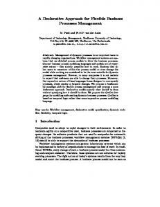
A Declarative Approach for Specifying User-Centric Communication Peter J. Clarke, Vagelis Hristidis, Yingbo Wang, Nagarajan Prabakar and Yi Deng School of Computing and Information Sciences Florida International University Miami, FL 33199, USA email: {clarkep, vagelis, ywang002, prabu, deng}@cis.fiu.edu ABSTRACT The rapidly growing, reliable network infrastructure available today is enabling several classes of communication and collaborative applications. Already, a wide range of communication applications, tools and services (e.g., IP telephony, instant messaging, digital video conferencing, and multimedia collaboration), and many domain- or industry-specific communication applications (e.g., telemedicine, disaster management, and defense) have been developed and deployed. However, these communication applications have been conceived, designed and developed vertically and separately with little or no connection to each other. In addition, there has been little or no attention paid to how the end-user specifies his/her communication needs when using these applications. We propose a new paradigm to define user-centric communications, which is based on a simple and declarative Communication Modeling Language (CML) and a network abstraction middleware, which we call Communication Virtual Machine (CVM). To clarify this paradigm we draw a parallelism to the transformation that has taken place in the data management domain over the last two decades. In this paper we focus on CML and present two concrete and equivalent variants, an XML-based and a graphical. We argue that the proposed CML can facilitate the specification of a wide range of user-centric communication scenarios in several domains. KEYWORDS: Data communication, modeling language, model-based development.
1. INTRODUCTION An increasing number of communication applications are being developed and deployed due to the continuous improvement in network capacity and reliability. Examples range from IP telephony, instant messaging, video conferencing, multimedia collaboration, to specialized communi-
cation applications for telemedicine, disaster management, and scientific collaboration [1, 11, 14, 17, 27]. Today, all trends indicate that the pace of innovation of new communication and collaborative applications is expected to accelerate further, given the growing support provided by the reliable and high-performance network infrastructure. Ackerman et al. [1] supports this claim by describing how the advances in technology are expected to influence the Telemedicine domain. Despite the advances in the areas of high-level programming languages (from Java to visual languages) and development environments (e.g., Eclipse 1 ), and the generation of numerous network libraries (e.g., TCP/IP Sockets), the development of a communication application remains a cumbersome and costly process. In addition to the development complexity, communication applications are tied to the networks considered at development time and cannot keep pace with the rapidly changing network specifications and capabilities (new protocols like SIP, WiFi IEEE 802.11, H323 [10]). In short, today there is no common model, architecture, or systematic method to specify communication services that are reconfigurable, and network- and deviceindependent. This significantly limits the pace of innovation for a new generation of communication tools, and thus slows down the return on massive investment on network infrastructure and limits industry growth. We present a new paradigm to develop and deploy usercentric communication applications which satisfies the following requirements: (a) be declarative and intuitive, (b) provide a level of abstraction on both the device and network specifics, and (c) integrate seamlessly with applications to handle their communication logic. Note we the term user represents an end-user or an application. This paradigm consists of a simple and declarative Communication Modeling Language (CML), and a network abstraction middleware, which we call Communication Virtual Machine (CVM). We identify the following major challenges 1 http://www.eclipse.org/
Figure 1: Parallelism to mediator technology in data management. to realize these requirements: First, what properties must a language possess to be intuitive yet powerful enough to model the majority of user-centric communication scenarios? Second, how can this modeling language fit into the process of application development in order to handle the communication-specific functionality (the communication logic)? Third, how can a communication scenario specified with this declarative modeling language be realized on a heterogeneous collection of networks and devices? In this paper we address the first two questions. We address the third question in [10], which is addressed in Section 2. Parallelism to data management. To better understand the proposed paradigm, we draw a parallelism to the data management area. Figure 1 captures the parallelism between the proposed paradigm and accessing heterogeneous data sources. As the use of computers and databases increases, we reach a point where data (for a particular organization or for the whole internet) is dispersed to a large number of sources with different data models (e.g., relational, XML, text, and so on), data schemas and querying interfaces (e.g., SQL, XQuery, and keyword search). However, applications require access to multiple of these data sources and researchers have found that developing specialized access mechanisms for each data source is cumbersome and also inflexible since if a legacy database is replaced by a newer one, the application has to be changed. Hence, the logical data abstraction paradigm has been proposed, to hide the specifics of the underlying sources and export a uniform interface to the applications for querying data. The right part of Figure 1 shows a popular mediator architecture [5], where Xquery [24] is used as the common data extraction
language. In the communication domain there is a similar need to abstract the underlying device and network infrastructure and provide a unified communication abstraction layer. The CVM plays the role of the mediator and it handles the execution of communication requests specified in CML (which corresponds to XQuery in Figure 1). The Network Communication Broker (NCB) [26], described in Section 2, plays the role of the data wrapper and provides an abstraction of the network and device specifics. Notice that the arrows between the left and right parts of Figure 1 depict the correspondences between the two paradigms. Contributions. In this paper we: 1. Propose a new paradigm for specifying user-centric communication. 2. Present a new Communication Modeling Language (CML) for user-centric communications. Two equivalent variants of CML are defined: an XML-based (XCML) and a graphical (G-CML). 3. Describe our prototype that supports our new paradigm for user-centric communication. 4. Present a case study on the communications needs in a real medical environment. We show how CML can model the communication needs for this environment. The paper is organized as follows. Section 2 provides an overview of the Communication Virtual Machine (CVM). Section 3 describes formally the two CML variants and the transformation between them. Section 4 presents our prototype and the details of the architecture of the CVM
layer where the user communication needs are specified. Section 5 discusses the related work and we conclude in Section 6.
2. CVM In this section we provide an overview of the Communication Virtual Machine (CVM) which enables the realization of the user communication needs specified using the Communication Modeling Language (CML). The essence of CVM is that it facilitates a user-centric communication defined using CML. As shown in Figure 2, CVM lies between the communication network and the user (or application). The user defines a communication scenario using CML, and CVM handles the execution of the communication. The design of CVM handles the common tasks performed by communication applications. These tasks include: presentation of the data/information being communicated, interfacing with user devices that are sources/sinks for the data/information, composition of the communication services that the application provides (to end-users), and interfacing with underlying communication network(s) that deliver the data/information. A key design principle of CVM is the separation of concerns. The flexibility of CVM comes from separating and encapsulating major aspects of communication concerns into individual compartments, which can be handled separately. At a broader level, CVM encapsulates the specification and processing of user communication logic into a horizontal layer cross cutting different communication applications and services, and by doing so, it allows us to uniformly and systematically address these concerns across these applications. In addition, it provides the conceptual basis to develop uniform interfaces to communication devices and networks and hence makes it possible to manage user communication transparent to the heterogeneity of device types, network protocols and configurations. As mentioned earlier, the CVM divides communication concerns into four major levels of abstraction. The four levels of abstraction, shown in Figure 2, represent the key artifacts of the CVM and include the: (1) user communication interface, which allows users to declaratively specify their communication needs and requirements (in CML), (2) synthesis engine, which provides the process and techniques to automatically synthesize a user communication instance (a specification of communication using CML as explained in Section 3) to an executable form called communication control script, (3) user-centric communication middleware, which executes the communication control script to manage and coordinate the delivery of communication services to
users independent of the underlying network configuration, and (4) network communication broker (NCB), which provides a network-independent API to the user-centric communication middleware and works with the underlying networks to implement the communication services. Each layer in the CVM model on the initiator side communicates virtually with its peer layer at the participant site (see Figure 2). The user communication interface communicates changes to a communication instance or schema (see Section 3) to its peer layer, the synthesis engine negotiates elements of the communication instances with its peer layer, the user-centric communication middleware performs the actual communication logic defined in the communication instance with its peer, while the network communication broker (NCB) handles session communication with its peer. This layered division of responsibility has similar principles to the well established OSI layered stack model for network communication [9]. The architecture of CVM offers the following desirable features: On-Demand Programmable and User-Centric Communication. Rather than being forced to use fixed, custom or generic communication products, CVM allows users to specify their communication needs (in CML). Horizontal Unification and Uniform User Experience. The design of CVM is network, device, and application independent. Hence, it is well positioned to serve as the ”middleware” to bridge the gap between network services and end-user communication needs, and allow the model to adapt to future changes in these areas. Automated Service Delivery and Dynamic Reconfiguration and Adaptation. The CVM has the ability to automatically generate communication applications from the declarative user communication instance and schema. This automated CVM synthesis process removes the need for costly software development required for stovepipe communication tools and makes on-demand composition of communication services possible. We now provide the intuition behind the role and feasibility of the synthesis engine (see [10] for details). The role of the synthesis engine is to automatically transform a declarative user communication instance to an imperative control script for the user-centric communication middleware. These control scripts represent the network- and device-independent control logic represented in CML. The synthesis engine puts together the control script by appropriately combining pre-defined scripts (e.g. schema and instance negotiation, communication session establishment, etc.) based on the user communication schema and instance. These scripts are created as services within the user-centric communication middleware, which in turn in-
Figure 2: Layered architecture of the Communication Virtual Machine. terfaces with the NCB to handle session establishment and media communication. The specifics of NCB and usercentric communication middleware are presented in [26], and will not be further discussed here. In contrast to general-purpose, model-driven application development [3], such synthesis is possible because of the following reasons. First, procedures and patterns governing basic communication services are well defined and well understood, and can thus be encoded into the transformation algorithms. Second, the combination of the code pieces cannot be performed in any arbitrary way, but only in limited and known-in-advance ways, since CML has limited expressive power. Third, the communication instance deals only with network-, device- and application-independent communication logic; and its structure is thus relatively simple. Section 3 defines in detail the exact expressive power of CML.
3. MODELING USER COMMUNICATION In this section we describe the requirements of a communication modeling language, which we distilled after studying several test cases and discussing with domain experts. Then, we present the Communication Modeling Language (CML) which is our proposed language to meet the stated requirements. In particular, we have identified the following requirements for the communication modeling language: Simplicity: Be simple and intuitive. Network-independence: Be independent of network and device characteristics.
Expressiveness: Model the large majority of communication scenarios 2 . In order to refine the expressiveness requirement, we identify the following primitive communication operations: 1. Establish a connection. 2. Specify requested properties for a connection or a particular data transfer. These properties include quality of service, security, access rights, suggested handling of transferred data. 3. Transfer a piece of data or a data stream. 4. Group the transferred data such that the receiving sides become aware of their association. 5. Close connection. Notice that the above operations are by no means an exhaustive list. We considered a much longer list but chose the above in order to build a minimal, intuitive and adequately expressive first version of CML. Other operators which we have considered but have postponed for later versions include communication constraints (e.g., if bandwidth is low then do not send video streams) and timing commands (e.g., transfer the sensor output every 5 seconds). The goal of CML as the first language in this area is to trigger the research community to start developing communication languages in order to eventually reach a well-accepted standard3 . 2 Similar
to SQL which can express the large majority of data queries the same way as XQuery emerged by combining multiple earlier XML language proposals 3 In
1.
userSchema ::= local connection {connection}
2.
connection ::= mediaAttached connection
3.
local ::= person isAttached device
4.
remote ::= device isAttached person
5.
mediaAttached ::= {medium} {form}
6.
device ::= device deviceCapability {deviceCapability}
7.
form ::= {form} {medium} | form
8.
person ::= personNameA personIDA personRoleA
9.
device ::= deviceIDA
10.
medium ::= builtinTypeA mediumURLA
11.
deviceCapability ::= builtinTypeA
12.
form ::= suggestedApplicationA actionA
13.
actionA ::= ”send” | ”doNotSend” | ”startApplication”
remote {remote}
suggestedApplicationA actionA
Figure 3: EBNF representation of X-CML. CML is used to define a communication schema as well as a communication instance 4 . A schema defines the allowed configurations and data transfers. The relation between a schema and an instance is like the relation between a class and an object. An instance is a diagram in which all fields are filled with actual values. It captures all information in a communication at a particular point in time, such as who are the participants, what kind of capability each device has, what is being transferred in this connection, etc. On the other hand, a schema only provides some configurations on what a conforming instance may contain. In particular, we can specify in a schema the types of participants (the personRole attribute of person in Figure 3), the types of transferred data (allowed builtin-Type in medium in Figure 3), and the capabilities of the involved devices (deviceCapability in Figure 3). On the other hand, an instance is created by instantiating the entities of a schema. For example, the abstract person entity in a schema is replaced by one or more person instances (persons with specified personIDs). We show examples of communication instances and schemas in Section 3.4. We present two equivalent variants of CML: the XML-based (X-CML) and the graphical (G-CML). The former is the version that CVM understands and processes, while the later was developed for user-friendliness reasons. In Section 3.3 we present algorithms for the automatic translation between X-CML and G-CML. Sections 3.1 and 3.2 describe X-CML and G-CML respectively.
3.1. X-CML X-CML is XML-based and hence its syntax is defined by an XML Schema. Appendix A [7] defines a generic communication schema, with no constraints on multiplicities, 4 Similar to how a database language (e.g., SQL) is used to define both the database schema and the database in-stance
Figure 4: Predefined (built-in) types for the CML. personRoles, and so on. For presentation purposes we have converted (and simplified) parts of this XML Schema to Extended Backus-Naur Form (EBNF) [22] form (stripping out reference constraints that cannot be represented in EBNF), shown in Figure 3, in order to explain the basic components of CML. Notice that Figure 3 depicts an attribute grammar, where attributes are denoted by an “A” subscript, terminals by boldface and non-terminal by italics. Figure 4 shows the hierarchy of builtin types (builtinTypeA ) currently supported in the CML implementation in CVM. CML defines a user-centric communication schema or instance. By user-centric we mean that all communications defined by a user in CML involve this user. This is shown in the first derivation rule of Figure 3, where a single “local” entity is defined for all connections the user is involved. A connection is a user session, and is defined as a communication between a group of participants where exchanged data is by default transferred to all participants. In addition to the local side, a connection contains a set of media (mediaAttached) currently transferred in the connections (session) and a set of remote participants (remote). Both local and remote participants are associated with a communication device (e.g., PC, cell phone), which is associated by a set of capabilities (deviceCapability). Notice how the specific characteristics of a device like type (PC or cell phone) or the network where it is connected (IP or cellular) are not defined, nor required. The reason is that CML operates on an abstraction of the underlying network and devices as mentioned above. We assume there is a single device per person, which can be relaxed in future versions if needed. A medium is a data piece or data stream, like a Word document or a live video feed respectively. A medium has a type which is one of the predefined types (builtinTypeA ) supported by the system, a mediumURLA that contains the location of the medium (a file location for a data piece or a port for a data stream), a suggestedApplicationA
∗
indicates zero or more occurrences.
+
indicates one or more occurrences.
The link connecting the symbol is also repeated
(a)
(b)
Figure 5: Grammar for the G-CML. which defines the application that can be used to view or process a medium (e.g., Powerpoint for ppt files), and an actionA which defines a default action that is performed on a medium. Actions “send” and “doNotSend” mean transfer automatically the medium or wait for the user to choose respectively, while ”startApplication” orders the system to open the suggested application of the medium once transferred.
Finally, we believe it is crucial to model complex data. For example, we present a medical scenario described in Section 3.4 that requires transfers of complex medical data consisting of multiple simple media. Complex data are represented using forms in CML, which are nested structures that contain media as well as user-defined attributes (e.g., media with common suggestedApplicationA or actionA settings can be grouped together in a form).
3.2. G-CML The graphical variant of CML (G-CML) is analogous to the E-R diagram [6] in the database world. The G-CML is used to create graphical communication models for both communication schemas and instances. Figure 5 shows the graphical language for G-CML. Figure 5(a) shows the nonterminal definitions of G-CML, while Figure 5(b) shows the terminal definitions. The number in the first column of Figure 5(a) corresponds to the equivalent production in the EBNF representation of X-CML, shown in Figure 3. For example, the first row of the table in Figure 5(a) shows the structure of the userSchema non-terminal, which consists of the local non-terminal connected to one or more connection non-terminals (connection). To indicate that a symbol may be repeated we use the character “∗ ” for zero or more repetitions and “+ ” for one or more repetitions. The first row of the table in Figure 5(b) shows the terminal for connection, which consists of a diamond shaped box with the label “connection”. The remaining non-terminals and ter-
Figure 6: G-CML instance for the medical scenario. minals in Figure 5 can be described in a similar manner. G-CML uses a notation similar to E-R diagrams, however the semantics are different. The symbols used in GCML can be classified into three categories, these include: (1) entities - person, device, medium and form, (2) relationships - connection and isAttached, (3) attributes properties of the entities (e.g., suggestedApplicationA ). Section 3.4 describes an example of how G-CML is used to model a medical scenario.
We use the numbers of the production rules to show the correspondence between the rules. For example in Figure 3, Rule 1 for the left production states that a userSchema, the start symbol, consists of a local non-terminal and one or more connections. The right production in Figure 5(a) also shows that a userSchema consists of the local non-terminal followed by one or more connection non-terminals. Note that the EBNF grammar shown in Figure 3 represents the generic communication schema defined in X-CML in Appendix A of [7].
3.4. Illustrative Example 3.3. Transformation between G-CML and XCML To achieve the transformation between X-CML and GCML and vice-versa we borrow techniques used in modelbased software development [13]. However, unlike the techniques used in model-based software development, our paradigm caters to a more restricted domain thereby providing us with the capability of easily automating the transformation process. The transformation between the two models is analogous to the concept of round-trip engineering in model-based software development. Heckel and Voigt [13] state that pair grammars are used to describe the source and target languages together with a correspondence between source and target sentences. The authors show how pair grammars may be used to transform UML models to BPEL4WS [13], we use a similar approach to convert between the communication models. The pair grammars we use in our models are shown in Figure 3 and Figure 5 respectively, where some details have been omitted due to space restrictions. We point out that the grammars in Figure 3 and Figure 5 are attribute grammars that is, terminals may have attributes associated with them. The left production rules of the pair grammar are shown in Figure 3 and the right production rules are shown in Figure 5.
To illustrate how CML is used to model the communication needs for an application we apply it to a real scenario from the medical domain, which we constructed with the help of our collaborators from the Miami Children’s Hospital (MCH) [4]. We show how the user communication needs are modeled using G-CML and the transformation to the equivalent X-CML. Scenario: Patient John Demo has been referred by Dr. Sanchez (a heart specialist) to the Miami Children’s Hospital (MCH) for heart surgery. Dr. Monteiro performs the surgery on patient John Demo. After surgery Dr. Monteiro contacts the referring doctor, Dr. Sanchez, to let him know that the surgery went well and to show him the echocardiogram (echo) of the patient. Dr. Monteiro also sends Dr. Sanchez the updated medical record for patient John Demo. We define the communication schema and instance using G-CML. Figure 6 shows the communication instance of the medical scenario. With the schema defined, we can construct this instance quickly by assigning actual values to the attributes associated with each entity and relationship. We do not show the schema due to space limitations. The participants in the communication instance shown in Figure 6 are Dr. Monteiro (the initiator) and Dr. Sanchez (the recip-
ient). The deviceCapabilities for each device in the connection are LiveAudio, VideoFile, and TextFile. A form is sent named PatientRec1, of formType PatientRec. The two media in this form are RecSummary.html (TextFile) and RecEcho.mpg (VideoFile). The corresponding XCML representation for the instance of Figure 5 is shown in Appendix B [7].
4. UCI PROTOTYPE To demonstrate the feasibility of using CML to specify the communication needs for user-centric applications, our research group has developed a prototype of the CVM. This prototype follows the layered architecture described in Section 2. In this section we describe the architecture of the layer where the communication logic is defined, the User Communication Interface (UCI), which is the top layer in the CVM (Figure 2). We also provide an overview of our working prototype using the scenario of Section 3.4.
4.1. Architecture of UCI Figure 7 shows a block diagram of the UCI and the two possible ways a user/application can interact with the UCI. The figure also shows the flow of control and data, between the user/application, the UCI and the Synthesis Engine (next layer in Figure 2). The UCI consists of four major components: (1) the communication modeling environment - provides the user with an environment to develop communication models (G-CML models) and transforms these models into an X-CML model, (2) the schema transformation environment - transforms a X-CML instance to a synthesisready-X-CML instance or stores the X-CML model to the repository, (3) the repository - stores artifacts (e.g., grammar rules and CML schemas) to support the creation of CML models and the transformation between CML models, and (4) the UCI to synthesis engine (UCI-SE) interface - provides a conduit for interaction with the synthesis engine. The main processing performed by the schema transformation environment is transforming the X-CML model into a synthesis-ready-X-CML model. This involves parsing the X-CML model to identify if: (1) values are required for any fields in the control or data parts of the X-CML, and (2) a form type is declared or used in X-CML. Any missing data is set to default values that was either saved by the user in a profile or to the system default values. User communication models may be submitted to the CVM for processing via the UCI using one of the two approaches, these are: (1) a user/developer interacting with the graphical interface in the communication modeling environment to develop a communication model (schema or instance), or (2) a user application submitting an X-CML instance of the
Figure 7: Block diagram of the User Communication Interface (UCI). user communication In the current version of the prototype we are using Visual Language Desk (VLDesk) system [8] as the graphical framework in the communication modeling environment to develop the G-CML model.
4.2. Application of CVM In our prototype, CVM is integrated with a medical R ) [23] to provide comdata retrieval system (i-Rounds munication between medical practitioners. Our prototype is a collaborative effort between the School of Computing and Information Sciences at FIU, Miami Children’s HosR R pital (MCH), Teges Corporation [23] and IBM . MCH is providing our research team with real scenarios in the Telemedicine domain. The article by Burke and White [4] from MCH describes how information technology is being used to improve clinical outcomes for a congenital heart R team. Teges provided us with access to the Integrated Clinical Information System (i-Rounds), which stores and displays all medical data in MCH. IBM provided expertise in the use of voice technology to interact with the i-Rounds system. Our prototype implements the scenario described in Section 3.4, i.e., sending a summary of a patient record after a surgery. To send the post-operation patient record the following steps are executed by the surgeon, Dr. Monteiro. We assume that Dr. Monteiro is still in the operating room. 1. Dr. Monteiro activates the i-Rounds system and retrieves the patient record for John Demo using the voice commands. 2. Dr. Monteiro activates the CVM client interface with a voice command.
3. Dr. Monteiro tells the CVM client interface to contact Dr. Sanchez. 4. Dr. Monteiro then tells the CVM client interface to send the patient record. After Dr. Monteiro retrieves the patient record using iRounds, the “patient dash board” (the page navigation tool in i-Rounds) is displayed with the CVM client interface embedded. As Dr. Monteiro performs steps 2 and 3 the communication model is created showing a connection between himself and Dr. Sanchez. When step 4 is perform the CVM send a form containing the current patient record to Dr. Sanchez. When the form arrives on Dr. Sanchez’s device the CVM displays the i-Rounds page containing the patient information. It should be noted that for user-friendliness purposes, a more high-level (icon-based) variant of G-CML is used that we internally map to G-CML. Additional information on the prototype, including screen shots, is provided in [7]. After Dr. Monteiro performs Step 3 shown above, the X-CML instance generated is shown in Appendix B [7]. This model is then passed to the CVM for processing. The UCI transforms the X-CML instance into a X-CML version ready for synthesis, validates the X-CML instance, and sends it to the synthesis engine for processing. The remaining layer of the CVM processes the request and delivers the contents of the media to the receiver’s CVM.
5. RELATED WORK Our survey of the literature revealed that although work has been done in the various areas of user-centric computing, there is currently no modeling language for defining user-centric communication models that is simple to use and has the expressiveness of CML. Although several model languages are used in software engineering and data modeling none of them posses the properties outlined in Section 3. We considered using a subset of UML 2.0 [19] but realized that in order to create a model of the data to be communicated and the logic of the communication several UML diagrams would be required. That is, we would require both static and dynamic UML diagrams to model the communication required by the user, thereby making the modeling process less user-centric. Many of the concepts exhibited in model driven software development (MDSD) [3] and model-driven architectures (MDA) [18, 20] are used in developing our CML. These concepts include the use of a visual modeling environment, meta-models, and model transformations. Unlike the approaches in MDSD and MDA we focus on a more restricted domain i.e., communication. Our G-CML language is similar to the E-R model [6] notation; however
the semantics we use are different. Unlike the E-R model, we represent instances of the schema and in some cases the entities have attributes that are shown in the entity box itself. We used VLDesk, a tool created by Costagliola et al. [8], to create the G-CML models in the UCI. However, the VLDesk tool lacks the functionality of transforming an XCML document into a G-CML model, a problem we are currently addressing. We applied the concept of the pair grammar during model transformation in the UCI [8, 13]. The modeling of the transmission media in the CML is conservative when compared to the other models used to describe media, such as the Dublin Core Metadata Initiative (DCMI) [12] or the Resource Description Framework (RDF) [25]. We decided to keep the attributes and actions associated with the media simple to cater for the novice user. However, we envision the extension of the attributes and actions, and the inclusion of constraints in the future version of the CML based on the DCMI and RDF. Anderson et al. [2] describes an architecture style that tightly couples the conceptual and implementation software architectures. This approach focuses on the development process of a multiuser interactive system by transforming the conceptual design into implementation details such as code and data distribution, caching and concurrency control. Phillips and Graham [21] present an architectural style for synchronous groupware that allows the developer to design a conceptual architecture and semi-automatically refine the design into an distributed implementation at runtime. Our approach to specifying communication models is similar to the that of scenario-based modeling by Phillips and Graham [21], except that we focus only on the communication aspect. Unlike these approaches [2, 21] of developing groupware, our approach focuses on providing the groupware user/developer with a means of specifying the communication requirements of the application. Communications services, such as the use of frameworks for IP-based telecommunication (JAIN SIP [15], and Java Media Framework [16], are usually tightly coupled with the user applications. Our approach allows for the decoupling of the communication services from the application logic thereby providing for (1) greater flexibility during maintenance, (2) the ease of extending the communication capabilities of the application, and (3) the ability to dynamically change the communication model at runtime.
6. CONCLUSIONS AND FUTURE WORK In this paper we presented a new paradigm to specify the communication needs of a user (end-user or application). A language (CML) was presented to specify the communication logic at a high-level thereby ignoring the partic-
ular characteristics of the underlying networks and devices. CML is supported by the CVM system [DSC05]. Furthermore, two variants of CML were presented, an XML-based (X-CML) and a graphical (G-XML), along with a description of the transformation process between them. In the future we will extend CML and then CVM to handle the new CML features. These features will allow the user to specify access control for various participant roles, constraints on the data communication, and a communication logging system. We envision that as more communication services become available to the user, CML will eventually become the language of choice to specify communication requirements. ACKNOLWEDGEMENTS This work was supported in part by the National Science Foundation under grant HRD-0317692. The authors would like to thank S. Masoud Sadjadi, Raju Rangaswami, and Chi Zhang for their contributions to this work.
References
[10]
[11] [12] [13]
[14] [15]
[16]
[17]
[1] M. Ackerman, R. Craft, F. Ferrante, M. Kratz, and H. S. Salah Mandil. Telemedicine technology. Telemedicine Jorunal and eHealth, 8(1):71–78, 2002. [2] G. E. Anderson, T. C. N. Graham, and T. N. Wright. Dragonfly: linking conceptual and implementation architectures of multiuser interactive systems. In Proceedings of the 22nd ICSE, pages 252–261. ACM Press, 2000. [3] J. Bettin. MDSD activities: The process view of an mdsd project. Technical report, SoftMetaWare, May 2004. http: //www.softmetaware.com/whitepapers.html. [4] R. P. Burke and J. A. White. Internet rounds: A congenital heart surgeon’s web log. Seminars in Thoracic and Cardiovascular Surgery, 16(3):283–292, 2004.
[18]
[19] [20] [21]
[5] S. Chawathe, H. Garcia-Molina, J. Hammer, K. Ireland, Y. Papakonstantinou, J. D. Ullman, and J. Widom. The TSIMMIS project: Integration of heterogeneous information sources. In Proceedings of of IPSJ Conference, pages 7–18. IEEE, Oct. 1994.
[22]
[6] P. P. Chen. The entity-relationship model: Toward a unified view of data. ACM Trans. Database Syst., 1(1):9–36, 1976.
[24]
[7] P. J. Clarke, V. Hristidis, Y. Wang, N. Prabakar, and Y. Deng. A unified architectural model for on-demand user-centric communications. Technical Report FIU-SCIS-2006-01-02, Florida International University, Jan 2006. http://www. cis.fiu.edu/˜prabakar/cts2006/ (Mar 2006). [8] G. Costagliola, V. Deufemia, and G. Polese. A framework for modeling and implementing visual notations with applications to software engineering. ACM TOSEM, 13(4):431– 487, 2004. [9] J. D. Day and H. Zimmermann. The osi reference model. In Conformance testing methodologies and architectures for
[23]
[25] [26]
[27]
OSI protocols, pages 38–44. IEEE Computer Society Press, Los Alamitos, CA, USA, 1995. Y. Deng, S. M. Sadjadi, P. J. Clarke, C. Zhang, V. Hristidis, R. Rangaswami, and N. Prabakar. A unified architectural model for on-demand user-centric communications. Technical Report FIU-SCIS-2005-09, Florida International University, Sep 2005. DisasterHelp. https://disasterhelp.gov/ portal/jhtml/index.jhtml (June 2005). Dublin Core Metadata Initiative (DCMI). http:// dublincore.org/ (Dec 2005). R. Heckel and H. Voigt. Model-based development of executable business processes for web services. LNCS, 3098:559–584, 2004. Internet2. Internet2 working groups, and special in-terest groups, June 2005. JAIN SIP. Internet2 working groups, and special in-terest groups, June 2005. https://jain-sip.dev.java. net/ (May 2005). Java Media Framework API. Internet2 working groups, and special in-terest groups, June 2005. http://java.sun. com/products/java-media/jmf/ (May 2005). S. Kim, K. Pan, E. Sinderson, and E. J. Whitehead. Architecture and data model of a webdav-based collaborative system. In Proceedings of the Int’l Symp. on Collaborative Technologies and Systems, pages 48–55. IEEE, Jan. 2004. MODA-TEL. Mda foundations and key technologies (Deliverable 3.4), July 2004. http://www.modatel.org/ (May 2005). OMG. Unified modeling language. http://www.uml. org/ (Dec. 2005). OMG. mda guide ver-sion 1.0.1, June 2003. http://www. omg.org/docs/omg/03-06-01.pdf (Mar. 2006). W. G. Phillips and T. N. Graham. Workspaces: A multilevel architectural style for synchronous groupware. In Proceedings of Design, Specification and Verification of Interactive Systems (DSV-IS 2003), pages 92–106. Springer LNCS, 2003. R. W. Sebesta. Concepts of Programming Languages. Addison Wesley, sixth edition, 2003. TegesTM Corporation. http://www.teges.com/ index.asp (Dec. 2005). W3C. XML Query (XQuery). http://www.w3.org/ XML/Query/ (Dec. 2005). W3C. Resource Description Language (RDF), June 2003. http://www.w3.org/TR/rdf-schema (Dec. 2006). C. Zhang, S. M. Sadjadi, W. Sun, R. Rangaswami, and Y. Deng. User-centric communication middleware. Technical Report FIU-SCIS-2005-11-01, Florida International University, Nov 2005. H. Zhu, M. Turoff, and Z. Li. An object model for collaborative systems and a toolkit to support collaborative activities. In Proceedings of the 2000 Americas Conference on Information Systems, pages 590–594, 2000.