Sensor plug-ins: one controlling a demo ping session, and another applying ... by the signature of the sender (not encrypted, in principle), which can be checked ...
1
A Demand Driven Network Monitoring Architecture Augusto Ciuffoletti, Yari Marchetti, Antonis Papadogiannakis, Michalis Polychronakis
Abstract—The capability of dynamically monitoring the performance of the communication infrastructure is one of the emerging requirements for a Grid. We claim that such a capability is in fact orthogonal to the more popular collection of data for scheduling and diagnosis, which needs large storage and indexing capabilities, but may disregard real-time performance issues. We discuss such claim analyzing the gLite NPM architecture, and we describe a novel network monitoring infrastructure specifically designed for demand driven monitoring, named gd2, that can be potentially integrated in the gLite framework. We describe a Java implementation of gd2 on a virtual testbed. Index Terms—Network Monitoring, gLite, Network Measurement, XML Schema Description, Java, User Mode Linux.
I. I NTRODUCTION End-to-end network monitoring is a key issue in the management of production Grids: network resources are used to move large quantities of data from data acquisition devices to (possibly replicated) storage units, and from there to data processing sites. In order to ensure a timely execution of data transfers, the performance of the network must be monitored before engaging in the data transfer operation, to check the availability of network resources, and during data transfer, to verify network resources performance. More advanced uses of the Grid paradigm potentials just emphasize the importance of Network Monitoring, for instance in the optimized management of a complex workflow, where the displacement of an activity can be evaluated after a network warning. The issue that differentiates network monitoring from other instances of resource monitoring is in the way its complexity scales up with the size of the system: while other resource monitoring activities (for instance processing power) scales linearly with the size of the system, network monitoring potentially grows with the square of the size of the system. To make a straightforward example, let us consider a system with 2 endpoints where a trivial ping with a period of 1 second consumes 0.1msec/sec of CPU (0.01%), 128 bps of bandwidth, and produces 1 line (80 Bytes) of data per second. In a system with 10 hosts the CPU load for each host raises to 0.1%, the consumed bandwidth raises to 6KBps, and data produced to 8 KBps. In a system with 100 hosts the CPU load is 1% of the computing power on each host, bandwidth is 0.5 MBps, and traffic grows at 800KBps. Our dummy system can hardly scale further 1000 endpoints: the limit comes from the computing power spent sending ICMP packets (10% on each host), and This research work is carried out under the FP6 Network of Excellence CoreGRID funded by the European Commission (Contract IST-2002-004265). Augusto Ciuffoletti is with INFN/CNAF - Via B. Pichat 6a - Bologna Italy Yari Marchetti is a student at Dept. of Computer Science of the University of Pisa - Largo Pontecorvo - Pisa - Italy Antonis Papadogiannakis and Michalis Polychronakis are with FORTH Heraklion (Crete) - Greece
from the amount of data produced (80MBps, more than the LHC experiment). Although simplistic, the example above justifies our claim that the network monitoring activity must be selective in its targets: only a significantly small fraction of end-to-end paths can be monitored at each time. As a consequence, whatever the criteria to select which path is to be monitored, we need some sort of distributed infrastructure in order to activate and deactivate network monitoring selectively. Such infrastructure is not needed by other kinds of monitoring activity: data about computing resources can be collected continuously, and historical records kept, while preserving system scalability. Another peculiar issue about network monitoring is software organization. When we consider other kinds of resources, for instance processing capabilities, monitoring tools are adapted to the resource itself, and the unique compatibility requirement on the monitoring tool is that the information it produces is compliant to some sort of standard, that makes it usable by other applications. When we come to network monitoring tools, we often observe that the monitoring tool requires some sort of cooperation from the environment: even the simplest tool, the ICMP ping, requires that packets are freely propagated, and this is not always true. More complex tools require that the endpoints participating in a monitoring activity share some functionality, and that the path between them cooperates in the measurement: the well-known Iperf tool belongs to this category. From such observation, we conclude that, if this were the case, network monitoring functionality should be equally available on each endpoint, and supported by the intermediate network elements. Such fact may make the deployment of a measurement methodology awkward. One way to overcome this problem is to use passive measurement techniques, instead of active. In fact, if we define an active monitoring tool as one that injects traffic and generalizes the treatment of such traffic to other kinds of traffic, the above discusses argues that such a generalization step is in fact critical: as a general rule, one cannot generalize, since different traffic instances are treated differently by network elements, which makes active measurements potentially deceptive. The solution, in our mind, is to analyze existing traffic: such solution is directly applicable to the problem of monitoring an ongoing application that makes use of network resources. The application to the case of a preventive monitoring (for instance, to assess the performability of a reserved resource) is less immediate: one option is launching a ”benchmark” test, and observe the performance of the network elements during the execution of the benchmark. As a general rule, there are two distinct approaches to implement a passive network performance measurement: either analyzing log files of the bandwidth consuming activity, or the traffic on network interfaces that passively observe traffic. The
2
first alternative exhibits some of the problems already observed for planned network monitoring: in fact, every potential endpoint should produce conformant data using a known protocol and offer an interface to activate and de-activate logging. This fact makes deployment problematic, as outlined above, while the computational overhead on a valuable resource is a comparatively less important drawback. So we opt for the second alternative, which is based on passive observation of existing traffic. Since the activity of traffic monitoring is a resource demanding task, which requires specific software, we consider as appropriate to delegate such activity to specialized units, located where it is possible to intercept traffic between endpoints. The result of such activity should be collected and published only after checking the credentials of the requester: such data should be regarded as subject to security restrictions. Results may be represented either according with a standard format, or using a ”tool aware” format: also in this case such modality should be explicitly indicated in the request. Summarizing, we establish two cornerstones for an end-toend network monitoring architecture capable of managing the scalability challenge offered by a Grid environment: • demand driven, in the sense that its activity is not set by default, or with static configurations, but controlled by external agents; • passive monitoring oriented, in the sense that only existing traffic is analyzed in order to obtain the requested measurements. The next section goes into the details of a novel architecture, named gd2, which is the result of a joint activity of INFNCNAF (Italy) and FORTH (Greece), in the frame of the European CoreGRID project. The gd2 architecture is based on a domain partitioning of endpoints, and operated by a number of agents in charge of controlling network monitoring activity. After introducing an abstract view of the architecture, we detail the internal structure of the basic agent, the Network Monitoring Agent, and introduce the formal description of the piece of data in charge of describing an instance of network monitoring activity. Finally we detail the software organization of a prototype implementation, written in Java: the prototype encompasses the Client agents, which submit network monitoring requests, the Network Monitoring Agents and two Sensor plug-ins: one controlling a demo ping session, and another applying sophisticated passive monitoring techniques to the observed traffic.
directory block in the referenced report. In our case we refer to a service which routes requests from consumers to producers. Such routing requires access to the global organization of the network monitoring infrastructure, and must enforce security policies that restrict access to network monitoring operation. Both facts indicate the option of restricting the set of agents enabled to perform such actions, avoiding to implement direct consumer to producer access and viceversa. Therefore the role played by the agents in the network monitoring infrastructure is more similar to that of a mediator, as in NPM, outlined in section III. BACKBONE
A
E
S S
E
E A
E E
Fig. 1. Deployed of gd2 components in a Domain: E units represent generic monitoring endpoints, A labeled units representNetwork Monitoring Agents, S units represent Network Monitoring Sensors
In gd2 architecture, as illustrated in figure 1, each Network Monitoring Agent (Agent, in the rest of this paper) takes the responsibility of managing a number of Network Monitoring Sensors (Sensors, in the rest of the paper), and of agents enabled to submit network monitoring requests, the Network Monitoring Clients(Clients, in the rest of the paper). Such a set of entities is indicated as a domain. There are good reasons to introduce such concept (roughly the same that motivate its introduction in many aspects of networking): • reducing complexity – one Agent concentrates the interface to the entities inside the domain; • security containment – security issues can be managed using local credentials inside the domain; • limiting global state access – only Agents have access to the global state, thus simplifying its management and ensuring security.
II. T HE COMPONENTS OF A DEMAND DRIVEN NETWORK MONITORING ARCHITECTURE
The Network Monitoring Infrastructure outlined in previous section identifies three distinct functionalities: producers of traffic observations, infrastructure agents that deliver requests to producers, and consumers, that issue requests and consume observations. Such a triad corresponds, in spirit, to the one introduced in a GGF report [2] that laid the foundations of the Network Monitoring Working Group [7]. However, we note, with respect to this architecture, one relevant difference in the role played by the infrastructure agents, that replace the
A. The Network Monitoring Agent The services offered by a Network Monitoring Agent can be divided into two quite separate interfaces: one towards the other NMAs (back end), and another towards local sensors and clients (front end). In figure 2 the triangular shapes indicate front end interfaces. We examine the two faces, and next detail the internal structure of the agent. The back end interface is in charge of maintaining the membership of the Agents in the system. Such membership is the repository of two relevant data: 1) the credentials of the
3
Data Transport Front end
Sensor IF Data
Stream IN
Back End
Client IF Data
Stream OUT
Session Soft State
Request OUT
Sensor IF Control
Request IN
Request Routing Front end
Client IF Request
Fig. 2. Internal architecture of a Network Monitoring Agent. The Back End interfaces are located in the innermost stripe
Agents, needed to enforce security in communications among the agents, and 2) the components of each domain. As for the first point, we assume that security mainly addresses authentication: communication among Agents is not considered as confidential. Therefore we envision a public/private key scheme as adequate for our purpose. In order to control access to the membership, we assume the existence of an external entity in charge of key creation and assignment. Such Authority, upon admission of a new agent, releases a certificate, which entrusts the use of the public key as authorized by the Certification Authority. Each Agent has access to a repository containing the certified public keys, and each communication within the membership is accompanied by the signature of the sender (not encrypted, in principle), which can be checked using the public key. The reader understands that the implementation of the certificate repository is a component whose implementation affects the scalability of the whole architecture: we deal with such component in section II-C. The back end, upon receiving a request, submits its content to the front end in order to assess its capability to take it up: it is possible that the information in the domain directory was insufficient to determine the appropriate Agent for the task. Therefore we consider that the front end may fail to fulfill a request: in such case, the back end will trap the failure, and resubmit the request to another Agent. Such rerouting will be controlled either by alternate Agents whose identity is indicated in the global directory (as a general rule several agents are responsible for the monitoring of a given network element), or by information available to the front end, obtained from inside the domain. We indicate the capability of re-routing requests as a ”Proxy” functionality. An Agent offers another back end service for the transport of Network Monitoring data to the Client that requested it: such transport service consists of a stream from the Sensor to the Client, and is routed transparently through the reverse of the path used to deliver the request. The content of the stream may be encrypted (as in the case of network monitoring tool illustrated in section IV-A), in case the network monitoring results are considered as confidential, but the client(s) must own the key to decrypt the data: here we assume that such keys
are negotiated when the network monitoring task is accepted for execution. The front end of the Agent is in charge of interacting with Clients and Sensors inside the Domain: the Agent accepts requests for Network Monitoring from the Clients, and drives the Sensors in order to perform the requested network monitoring activity. The network monitoring activity is organized into Network Monitoring Sessions (or Sessions, in the rest of this paper). A session describes the endpoints of the Network Monitoring activity, as well as the kind of activity required. The request must determine, either implicitly or explicitly, the features of the stream that will be produced to return observations to the Client. In section II-B we give an XML Schema Definition for such data structure, the Session Description. The Clients submit their requests to the Agent as Session Descriptions. The Agent is in charge of checking whether the request comes from an authorized client: this functionality is supported by a trust supported internally to the domain, independent from that used within the membership of the agents. This allows the possibility of merging domains with distinct security policies and support. The request is then passed to the back end. The front end, upon receiving a request from the back end, analyzes its content to assess its ability to configure a Sensor that performs the task: to this purpose, the Agent must have access to a directory, internal to the domain, containing the descriptions of the sensors. B. Summary of the Network Monitoring Session Description The data contained in a Network Monitoring Session Description (for short Session Description) (see also [5] for an exhaustive description) is ideally split into three parts: one that is manipulated only by the Client, one that is updated by Agents, together forming an envelope carrying data that are relevant for the delivery, one that is delivered untouched from the Client to the Sensor and carries the modality of the monitoring activity. In table I we see the first part of the XSD document. A SessionId string is used to uniquely identify a session: such identification will be used also for routing the data stream. The extent of a monitoring activity is specified by a Schedule element, which also contains indications of the resource required by the data stream. The SessionId and the Schedule characterize a Session, and are delivered from the Client to the Agent. They are not changed en route. The Agent complements such data with others concerning the treatment of the Session: they are modified by the agents themselves, and are represented as attributes. The RequestFrom element indicates the source of the request, and is used for admission control: in principle, several requesters may be indicated. The NetworkElement indicates the domains involved in the monitoring, and is used to select the appropriate Agents to deliver the request. The Route element is modified while the request is propagated, and it is used for backward delivery of the data stream. The inner part of the Session Description consists of a complex element, the MeasurementStream illustrated in table
4
TABLE I I NTER - AGENT PART OF THE N ETWORK M ONITORING R EQUEST S CHEMA D ESCRIPTION
TABLE II T HE MEASUREMENT SPECIFIC PART OF THE N ETWORK M ONITORING R EQUEST S CHEMA D ESCRIPTION
II, that details the kind of data that are requested from the monitoring activity. Such element is passed as is from agent to agent without being processed. In principle such element might be encrypted, if required by security reasons. As explained above, we are not interested at this stage in secreting monitoring results and activity. The MeasurementStream element is made of a common part, and another which is specific for each measurement tool. The common part lists a CharacteristicStreamId attribute, a sampling period SamplePeriod together with the monitoring end-points ( SourceIP and DestinationIP ), which together broadly characterize the monitoring activity. The tool specific
part is one of a choice of elements: such elements may be specific for a given tool, or generically address any tool that may produce data conformant to a certain standard. We have presently developed and used in our testbed a description for a trivial ping, useful only for demo purposes and documentation, and a passive monitoring tool, which is able to produce a wide range of measurements. C. The Domain Database In order to understand the role of the Domain Database, we illustrate the decisions that the Agents take on the basis of its content. The first decision step on this way is performed by the Agent once it receives a request from a Client: it consists in determining the Source and Destination domains of the network element under test. Such information is obtained by way of a query to the Domain Directory. The request is then forwarded to an Agent in such domains: the identity of such agents and their address is again obtained from the Domain Directory. We exclude that a monitoring activity is performed by an intermediate domain, since this would require the availability of routing information for the overall system. Each agent on the way of the Request will in turn check the signature associated to the request, and replace it with its own. A query to the Domain Directory returns the public key needed to check the signature. Each agent in turn will check the availability of the network monitoring functionality within the domain. This step is performed without further access to the Domain Directory, but browsing the capabilities available within the domain. We emphasize that our perspective helps to simplify this task: the adoption of passive tools helps us in limiting the number of potential producers (the sensors) in our architecture. Therefore the search for a producer is restricted within a limited number of sensors: such search can be either based on a local directory, or simply carried out broadcasting the request template to the local sensors. The above discussion explains why the Domain Directory is to be considered a critical component in the structure: it is a potential single point of failure, and a performance bottleneck. A centralized implementation is therefore incompatible with the scalability of our architecture. However, the information stored in the Domain Directory is seldom updated, and this opens the way to strongly distributed solutions. There are several options, that depend on the scale of the Grid of concern. One is to apply to a LDAP or DNS based implementation. Such well known tools are ready solutions for the maintenance of a distributed directory, that allow data replication in order to improve performance and fault tolerance. Such solutions are probably adequate to most current scenarios. Going beyond such scale, we indicate the implementation of fully delocalized solutions: in essence, all Agents cache a part of the database, and updates are propagated according with a peer to peer protocol. Such approach may significantly improve scalability, while reducing the footprint for the maintenance of the Domain Directory. A theoretical investigation
5
about the topic are reported in [3], while experimental results are in [4]. III. C OMPARISON WITH G L ITE NPM ARCHITECTURE
IV. I MPLEMENTATION OF A D EMAND D RIVEN N ETWORK M ONITORING A RCHITECTURE This section is devoted to the description of an implementation of the above architecture for a network monitoring system. An evaluation prototype has been written for Linux in Java, a language that facilitates porting and enforces a clear, modular design. Sensor Plugins
The NPM architecture [9] is one of the most promising proposals for network monitoring, and is presently embedded in the gLite infrastructure, designed and implemented in the framework of the European Project EGEE. NPM is designed to provide two types of information: measurement data, in the form of data records conforming to OGF standards, and metadata, indicating what kind of data are available for a given network element. Such information is delivered to clients, whose role is typically to detect and diagnose network performance problems. The client submits its request to intermediate entities, the mediators through a web service interface. Such request may either exhaustively describe a measurement series, or ask for the retrieval of metadata about the measurements available for a given network element. In the former case, the requested data will be delivered to the client, while in the latter the client will be presented with a list of available measurements to choose from. In either case the mediator will use services offered by another kind of component, the discoverer, which is in charge to either locate the requested data, or to produce the listing of available sources. The source of the monitoring data is called framework, and it provides access to the tools that extract network monitoring data. A detailed description of the above services is in [10]. NPM strongly focuses on the accessibility of historical data: this makes a relevant difference compared to our perspective. In fact, since we mainly address data collected on demand, we necessarily exclude, for performance reasons, a web service oriented architecture for the retrieval of measurements. Instead we introduce a long lived communication entity, a stream. For the same reason we need not to address a large database of collected data: data are delivered to interested users, without being stored anywhere (unless a Client wants to do so). This avoids the need of indexing data, one of the functionalities associated to the discoverer. In our architecture the discovery activity focuses on a far less complex task: determining where to fire the measurement session. We conclude our discussion remarking that a direct comparison is in fact inappropriate: the two frameworks, NPM and gd2 address two distinct problems, and each of them is a poor solution when applied to the problem for which it has not been explicitly designed. NMA is designed to diagnose network problems once they have been detected, but has no detection tools: here we present a framework that helps detecting a network problem, and possibly overcome its presence without diagnosing its source. The NPM has an extremely heavy footprint when used to receive real time updates of the performance of a network element, which is needed to detect problems; our framework has no way to explore the past of an observation, tracking up to its cause. Since their application domains are different, one may guess that they may live side-to-side in the same infrastructure. We believe that this is possible, at least in perspective. For
instance, a client in our framework might be embedded in a NPM framework: its request might consists of a long-lived, continuous monitoring activity, and the flow of observations might be recorded for future use of NPM diagnostic tools. However, such a publication modality cannot replace the stream introduced in gd2, when the client is an entity in charge of monitoring the real time performance of an end-to-end path.
Domain Database
NMEManager
IAgentRetriever
StreamProxy
NMEDispatcher
RequestManager IRequestListener
ConnectionState
Soft State
SimpleHTTPServer
SOAP
Fig. 3.
Modular view of a Network Monitoring Agent
The internal structure of an Agent is illustrated in figure 3: the NMA is a multi-threaded daemon. The StreamProxy component is in charge of passing through the streams of data from sensors: it implements the ”Stream IN, Stream OUT” boxes in Figure 2. It is composed of a variable number of threads that implement a multistage pipe: each pipe stage performs a different action on the stream’s packets before passing to the next one. The actions performed by the stages are: 1) Packet receiving 2) Packet’s signature verification 3) Packet’s next destination selection 4) Packet’s new signature creation 5) Packet sending. Each of these stages (except for the first one) can be implemented by more than one thread by setting a specific config file parameter (default to one per stage): this can be useful on multicores/multiprocessors system. Each monitoring stream packet passing through the StreamProxy is a UDP packet with an additional specific header which allows packet’s stream identification and sender authentication. As specified in section II-B, packets belonging to the same session are identified by means of the SessionId parameter, present in every packet’s header.
6
Packet signature is included in the header and has a variable length: it depends on the algorithm and key length used for generation. For example, in our prototype it defaults to a SHA1 with RSA algorithm combined with 512 bits long keys which produces 64 bits long signatures. We opted for this signature length because we felt it was the right compromise between security and packet transmission overhead; it is possible however to change these options to increase security or lower the transmission overhead as needed. The first pipe stage, the packet receiving one, keeps listening on a specific UDP port for incoming monitoring stream packets and just relays them to next pipe stage, signature checking. The signature verification stage, reads the SessionId from packet header, and accesses the shared soft state associated with it in order to get sender identity. Using that information it can then access the Domain database, through IAgentRetriever, in order to retrieve its public key and check packet signature. Packet destination selection is next pipe stage: it performs the actual routing by determining the next packet destination. This is achieved by accessing the soft state, through the ConnectionState interface, and the Domain database. The signature creation stage just signs packet data, using the private key of the agent, before passing to the sending stage which takes care of delivery. The RequestManager is another thread, in charge of routing network monitoring requests, and implements the ”Request IN, Request OUT” boxes in Figure 2. Requests are acquired by a SimpleHTTPServer thread that offers a SOAP interface to the Clients and other agents. We used HTTP to pass requests to the agent: although it has a higher communication overhead compared with other types of transport (like TCP), we felt this was outweighted by the ease of deployment (due to firewalls, for instance). Each monitoring request passed to the agent is enveloped in a custom XML frame containing request signature, encoded using a Base64 positional notation. The request can be subsequently routed to another agent or to the NMEManager, depending whether it is local or not. Routing and signature checking in the RequestRouter are done similarly as in the StreamProxy described above. The NMEManager controls the Sensors through a set of dynamically loaded plugins: each plugin is specifically designed in order to drive a certain kind of sensor. When a monitoring request is passed to the NMEManager it checks, in a internal cache, if a suitable plugin has already been loaded. In that case the request is passed so it can configure the sensor to perform the required monitoring and so on to monitoring itself. Otherwise the NMEManager looks for one in a specific directory where sensors plugins live, and dynamically loads a suitable one if one is found. Before being considered appropriate for a given request, a plugin has to pass some tests the NMEManager performs: among others, it has to adhere to the NMEPlugin interface. To simplify the task of plugin implementation, some guidelines have been created for plugin’s development.
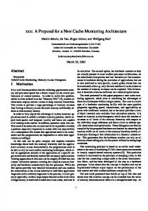
Fig. 4. Invoking a passive measurement for packet loss ratio in gd2: a plugin inside NMA initiates a DiMAPI program which gathers results from two remote sensors
A. Invoking Passive Network Measurements Passive monitoring sensors are usually located at selected vantage points in the network that offer a broad view of the traffic of a domain, such as the access link that connects a LAN with another, or an Autonomous System to the Internet. To support passive network measurements using the gd2 architecture, we have developed a plugin within the Network Monitoring Agent which controls the passive monitoring sensors. The passive monitoring plugin first receives the configuration parameters for the passive network measurements from the client’s request. These parameters are derived from the measurement specific part of the session description document, while the MAPIOptions element provides the relevant parameters for the passive monitoring tools. Depending on the request’s parameters, the user can choose between a variety of passive monitoring tools which measure different network metrics, such as round-trip time [6], packet loss rate [8], available bandwidth, and per-application bandwidth usage [1]. All these tools have been implemented using the Distributed Monitoring Application Programming Interface (DiMAPI) [12]. DiMAPI facilitates the concurrent programming and coordination of several remote passive monitoring sensors through a single application. When the starting time of a measurement comes, the passive monitoring plugin invokes the execution of a DiMAPI program that implements the chosen passive monitoring tool. Using the DiMAPI functionality, this program coordinates the available remote monitoring sensors that correspond to the requested domains. Through the DiMAPI interface, all the involved monitoring sensors are properly configured for the upcoming measurement and then they start monitoring the traffic and performing the actual passive measurements. The sensor’s configuration includes the specification of packet filters, the definition of the processing operations that should be performed for each network packet, and the kind of results that should be produced, using the suitable DiMAPI functions [12]. The measurement results from each sensor are periodically sent to the DiMAPI program, which is responsible for correlating and further collectively analysing the gathered results before returning them to the plugin in the NMA, with the period and duration defined at the user’s request. Finally, the plugin parses the results and sends them to the consumer through an encrypted connection. Figure 4 presents an example of a passive measurement ses-
7
sion for the packet loss ratio between two different domains: we emphasize that such a measurement requires sophisticated techiques in order to be performed according with a passive approach to network monitoring. Initially a client submits a request to the local NMA (1), and the request is forwarded to a corresponding NMA (2) that should perform the measurement. Then, the passive monitoring plugin parses the request and initiates the execution of a DiMAPI program that computes the packet loss ratio between the two domains using data from two corresponding monitoring sensors. The program first configures the two sensors (3) and then the results are streamed from the sensors to the DiMAPI program (4), which computes the packet loss ratio and reports it to the passive monitoring plugin. Finally, the results are streamed to the local NMA (5) and to the client (6). We have currently implemented the passive monitoring plugin to support appmon [1], a DiMAPI based tool that reports the accurate bandwidth usage for individual protocols and applications, and packet loss [8] measurement tools.
B. Prototype layout and operation The purpose of our prototyping was to assess the feasibility of the whole gd2 architecture, focusing on the communication infrastructure: therefore we tried to concentrate our efforts in order to produce a real scale support for a community of Agents, leaving behind other aspects of our architecture. We implemented a fully functional request delivery infrastructure, as well as the streaming in charge of returning the data to the requester. We took into account the security issues mentioned above, introducing signed communications among the Agents, taking care of the organization of the data stored in the Domain Directory. One of the aspects that are considered to a limited extent is the implementation of the Domain Directory: we have implemented a solution based on an LDAP directory, whose scalability is similar to other solutions based on this technology. We understand that this is a limit to the scalability of our prototype, but the implementation of an extremely scalable solution, given the necessarily limited scale of the experiment, was pointless. In order to debug and demonstrate the functionality of our architecture, we have implemented a virtual testbed using the NETKIT toolset [11], based on the User Mode Linux technology, which allows to virtualize several distinct hosts using a single computer. The virtual hosts appear as complete PCs, with independent storage, computing and networking facilities. They can be interconnected using ordinary interconnection tools, and form a virtual network. Aside from the limited amount of resources needed to synthesize the testbed, the major advantage of such an approach is that the experiments can be easily replicated on distant sites, thus allowing a collaborative development of the software without the need of sharing hardware facilities, and always run under extremely controlled conditions. Demonstrations can be produced using any available Linux machine, and without
installing experimental software on the real computer1 .
HOST 192.168.66.1 192.168.66.2 10.0.0.1
10.2.0.1
r1
10.1.0.1
10.2.0.2
Zeus
Fig. 5.
r2 10.255.1.1
10.0.0.2
10.1.0.2
Apollo
10.255.1.2
Ares
Development testbed
In our testbed we synthesize a network composed of three Agents and two routers (see figure 5): each of the Agents lives in a distinct domain. One of the Agents was equipped of a Client interface able to generate Network Monitoring Requests. We observed the delivery of a Request to the Sensor, with one or more hops within the NMAs membership, and the flow of observations from the Sensor to the Client. V. C ONCLUSIONS Our investigation, which attained the detail of a real scale implementation, lead to a clear view of the problems related to on demand network monitoring, and to the change of attitude needed with respect to the, so to say, diagnosisoriented network monitoring. A demand driven architecture is not data-centric, in the sense that storage and indexing of measurements are not relevant, but more capability-centric, in the sense that operational network monitoring capabilities must be indexed, and protected against misuse. Therefore we need an architecture that is able to give a structure to the membership of the components that have monitoring capabilities, so to provide a capability based addressing of the monitoring resources. We have identified such structure in a topology-bound partitioning: such structure must be sufficiently stable, in order to allow a distributed management of the directory that describes such partitioning. In order to effectively abstract from the internal structure of a domain, we introduce components that manage the monitoring capabilities within a domain. The primary security need is to avoid unauthorized access to network monitoring capabilities: to this purpose we need a robust authentication scheme, which is again based on information contained inside the distributed directory. Data transfer must focus on long lived, low bandwidth data transfers: a less than best effort paradigm seems appropriate for their definition. This seems to match with a stream oriented protocol, that uses routing information obtained during the delivery of the network monitoring request. In such scenario, passive monitoring is not only an option motivated by a low footprint. Passive end-to-end monitoring 1 The package with the virtual testbed (designed for Ubuntu Linux) is available at http://www.di.unipi.it/∼augusto/gd2-testbed.tgz, with instruction for its installation
8
capabilities can be concentrated in a few locations within a domain, thus simplifying the indexing of available capabilities, instead of scattered on each possible endpoint: which comes as a crucial advantage also in the deployment of the network monitoring infrastructure. R EFERENCES [1] Demetres Antoniades, Michalis Polychronakis, Spiros Antonatos, Evangelos P. Markatos, Sven Ubik, and Arne Øslebø. Appmon: An application for accurate per application network traffic characterization. In In IST Broadband Europe 2006 Conference, 2006. [2] Ruth Aydt, Dan Gunter, Warren Smith, Martin Swany, Valerie Taylor, Brian Tierney, and Rich Wolski. A grid monitoring architecture. Recommendation GWD-I (Rev. 16, jan. 2002), Global Grid Forum, 2000. [3] A. Ciuffoletti. The wandering token: Congestion avoidance of a shared resource. In Austrian-Hungarian Workshop on Distributed and Parallel Systems, page 10, Innsbruck (Austria), September 2006. [4] Augusto Ciuffoletti. Secure token passing at application level. In 1st International Workshop on Security Trust and Privacy in Grid Systems, page 6, Nice, September 2007. [5] Augusto Ciuffoletti, Antonis Papadogiannakis, and Michalis Polychronakis. Network monitoring session description. In CoreGRID Workshop at the International Supercomputing Conference, page 15, Dresden, June 2007. [6] Hao Jiang and Constantinos Dovrolis. Passive estimation of tcp roundtrip times. SIGCOMM Comput. Commun. Rev., 32(3):75–88, 2002. [7] Bruce Lowekamp, Brian Tierney, Les Cottrell, Richard Hughes-Jones, Thilo Kielmann, and Martin Swany. A hierarchy of network performance characteristics for grid applications and services. Technical Report GFDR-P.023, GGF Network Measurements Working Group, May 2004. [8] Antonis Papadogiannakis, Alexandros Kapravelos, Michalis Polychronakis, Evangelos P. Markatos, and Augusto Ciuffoletti. Passive end-to-end packet loss estimation for grid traffic monitoring. In Proceedings of the CoreGRID Integration Workshop, 2006. [9] Alistair Phipps. Network performance monitoring architecture. Technical Report EGEE-JRA4-TEC-606702-NPM NMWG Model Design, JRA4 Design Team, September 2005. [10] Alistair Phipps. NPM services functional specification. Technical Report EGEE-JRA4-TEC-593401-NPM Services Func Spec-1.2, JRA4 Design Team, October 2005. [11] Massimo Rimondini. Emulation of computer networks with Netkit. Technical Report RT-DIA-113-2007, Roma Tre University, January 2007. [12] Panos Trimintzios, Michalis Polychronakis, Antonis Papadogiannakis, Michalis Foukarakis, Evangelos P. Markatos, and Arne Øslebø. DiMAPI: An application programming interface for distributed network monitoring. In Proceedings of the 10th IEEE/IFIP Network Operations and Management Symposium (NOMS), April 2006.