tem, situated agents must be able to adapt their behavior. A well-known family of agent architectures for adaptive behavior are free-flow archi- tectures. However ...
A Design Process for Adaptive Behavior of Situated Agents Elke Steegmans, Danny Weyns, Tom Holvoet, and Yolande Berbers AgentWise, DistriNet, Department of Computer Science, K.U.Leuven Celestijnenlaan 200 A, B-3001 Leuven, Belgium {Elke.Steegmans, Danny.Weyns, Tom.Holvoet, Yolande.Berbers}@cs.kuleuven.ac.be
Abstract. Engineering non-trivial open multi-agent systems is a challenging task. Our research focusses on situated multi-agent systems, i.e. systems in which agents are explicitly placed in an environment which agents can perceive and in which they can act. Situated agents do not use long-term planning to decide what action sequence should be executed, but select actions based on the locally perceived state of the world and limited internal state. To cope with change and dynamism of the system, situated agents must be able to adapt their behavior. A well-known family of agent architectures for adaptive behavior are free-flow architectures. However, building a free-flow architecture based on an analysis of the problem domain is a quasi-impossible job for non-trivial agents. To tackle the complexity of designing adaptive agent behavior based on a free-flow architecture, suitable abstractions are needed to describe and structure the agent behavior. The abstraction of a role is obviously essential in this respect. A modeling language is needed as well to model the behavior of the agents. We propose a statechart modeling language to support the design of roles for situated agents. In this paper we describe a design process for adaptive behavior of situated agents as part of a multi-agent oriented methodology. The design process integrates the abstraction of a role with a free-flow architecture. Starting from the results of analysis of the problem domain, the designer incrementally refines the model of the agent behavior. The resulting class diagram serves as a basis for implementation. We illustrate the subsequent design steps with a case study on controlling a collection of automated guided vehicles.
1
Introduction
Dealing with the increasing complexity of developing, integrating and managing open distributed applications is a continuous challenge for software engineers. In the last fifteen years, multi-agent systems have been put forward as a key paradigm to tackle the complexity of open distributed applications. In our research we focus on situated multi-agent systems1 (situated MASs) as a generic approach to develop self-managing open distributed applications. 1
Alternative descriptions are behavior-based agents [5], adaptive autonomous agents [14] or hysteretic agents [10][9].
J. Odell et al. (Eds.): AOSE 2004, LNCS 3382, pp. 109–125, 2005. c Springer-Verlag Berlin Heidelberg 2005 �
110
E. Steegmans et al.
In situated multi-agent systems, agents and the environment constitute complementary parts of a multi-agent world that can mutually affect each other. Situatedness places an agent in a context in which it is able to perceive its environment and in which it can (inter)act. Situated agents do not use longterm planning to decide what action sequence should be executed, but select actions based on the locally perceived state of the world and limited internal state. Contrary to knowledge-based agents, situated agents do not emphasize internal modeling of the environment. Instead, they favor to employ the environment itself as a source of information. The environment can serve as a robust self-revising common memory for agents. This can unburden the individual agents from continuously keeping track of their knowledge about the system. Intelligence in a situated MAS originates from the interactions of the agents in their environment rather than from the capabilities of the individual agents. Agents interacting form an organization in which they all play and execute their own role(s). Situated MASs have been applied with success in numerous practical applications over a broad range of domains, e.g. manufacturing scheduling [20], network support [3] or peer-to-peer systems [2]. The benefits of situated MAS are well known, the most striking being flexibility, robustness and efficiency. To cope with change and dynamism of the system, situated agents must be able to adapt their behavior according to the changing circumstances. A well-known family of agent architectures for adaptive behavior are free-flow architectures [21][23][6]. Free-flow architectures allow adaptive behavior, yet from our experiences we learned that it is unrealistic to assume that -starting from the analysis of the problem domain- software engineers build a complex free-flow architecture for complex applications, where agents can perform many actions. For such applications, the architecture quickly becomes unmanageable, it is no longer possible to have an overall view of the architecture. To tackle the complexity of designing adaptive agent behavior based on a free-flow architecture suitable abstractions are needed to describe and structure the agent behavior. The abstraction of a role is obviously essential in this respect, as roles provide the building blocks for social organization of a MAS. A modeling language is needed as well to model the behavior of the agents. We propose a statechart modeling language to support the design of roles for situated agents. In this paper we describe a design process for adaptive behavior of situated agents as part of a multi-agent oriented methodology. The design process integrates the abstraction of a role with a free-flow architecture. We illustrate the subsequent design steps with a case study on controlling a collection of automated guided vehicles. This paper is structured as follows. In section 2 we introduce free-flow architectures and outline the design process for adaptive agent behavior. Section 3, the core of the paper, explains in detail the different steps of the design process for roles proposed in this paper. We illustrate our design process with an example application. Finally, in section 4 we conclude the paper and give some future work.
A Design Process for Adaptive Behavior of Situated Agents
2
111
Free-Flow Architectures and Designing Adaptive Behavior
In this section we start with a brief introduction of free-flow architectures and illustrate the complexity of developing a free-flow architecture for non-trivial agents. Then we outline the design process for adaptive agent behavior we propose in this paper. 2.1
Free-Flow Architecture for Adaptive Agent Behavior
Open multi-agent systems are characterized by dynamism and change: new agents may join the system, others may leave, the environment may change, e.g. its topology or its characteristics such as throughput and visibility. To cope with such dynamism the agents must be able to adapt their behavior according to the changing circumstances. A well-known family of agent architectures for adaptive behavior are free-flow architectures. Free-flow architectures are first proposed by Rosenblatt and Payton in [21]. In his Ph.D thesis, T. Tyrrell [23] demonstrated that hierarchical free-flow architectures are superior to flat decision structures, especially in complex and dynamic environments. The results of Tyrrell’s work have been very influential, for a recent discussion see [6]. An example of a free-flow architecture is depicted in Fig. 1. ����� ����
��� �� �� ��
� ��� ��� ������
����� �
��� ��
� ������
��
!"#
��
� ������ ��� ��
� ������
��
�������
�������
�
�
���� �
��� ������
���� �� ������
�
������� ��� �� �������
��� �����������
��� ������ ���� ��� �� �� ������ � ���� ���
��� �� ���� �� �������
�
�
��������� � ������
������������
� � ���� ���������
� ��
�
� � �
� � �
� � �
� � �
�� �������
� � �� ����������
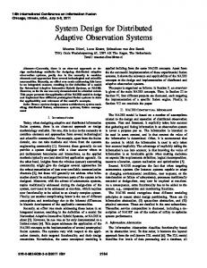
Fig. 1. An example of a free-flow architecture
The hierarchy is composed of nodes which receive information from internal and external stimuli in the form of activity. The nodes feed their activity down through the hierarchy until the activity arrives at the action nodes (i.e. the leaf nodes of the tree) where a winner-takes-it-all process decides which action is selected. The main advantages of free-flow architectures are:
112
E. Steegmans et al.
– Stimuli can be added to the relevant nodes avoiding the ’sensory bottleneck’ problem. In a hierarchical decision structure, to make correct initial decisions, the top level has to process most of the sensory information relevant to the lower layers. – Decisions are made only at the level of the action nodes; as such all information available to the agent is taken into account to select actions. – Since all information is processed in parallel the agent can take different preferences into consideration simultaneously. E.g. consider an agent that moves to a spotted object but is faced with a neighboring threat. If the agent is only able to take into account one preference at a time it will move straight to the spotted object or move away from the threat. With a freeflow decision tree the agent avoids the threat while it keeps moving towards the desired object, i.e. the agent likely moves around the threat towards the spotted object. Fig. 1 depicts a free-flow tree for action selection of a simple robot. This robot lives in a grid world where it has to collect objects and bring them to a destination. The robot is supplied with a battery that provides energy to work. The robot has to maintain its battery, i.e. when the energy level of the battery falls below a critical value the robot has to recharge the battery at a charge station. The left part of the depicted tree represents the functionality for the robot to search, collect and deliver objects. On the right, functionality to maintain the battery is depicted. The System node feeds its activity to the Work node and the Maintain node. The Work node combines the received activity with the activity from the energy level stimulus. The ’+’ symbol indicates that the received activity is summed up. The negative activity of the energy level stimulus indicates that little energy remains for the robot. As such the resulting activity in the Work node is almost zero. The Maintain node on the other hand combines the activity of the System node with the positive activity of the energy need stimulus, resulting in a strong positive activity. This activity is fed to the ToStation and the Charging nodes. The ToStation node combines the received activity with the activity level of the not at station stimulus (the ‘*’ symbol indicates they are multiplied). In a similar way the Charging node combines the received activity with the activity level of the at station stimulus. This latter is a binary stimulus, i.e. when the robot is at the charge station its value is positive, otherwise it is negative. The ToStation node feeds its positive activity towards the action nodes it is connected to. Each moving direction receives an amount of activity proportional to the value of the gradient stimulus for that particular direction. gradient is a multi-directional stimulus, i.e. a compound stimulus with a value of the stimulus for each direction. The values of the gradient stimulus are based on the sensed value of the gradient field that is transmitted by the charge station. In a similar way, the Charging node and the child nodes of the Work node (Explore, Collect and Deliver ) feed their activity to the action nodes they are connected to. Action nodes that receive activity from different nodes combine that activity according to a specific function. The action nodes for moving actions use a function fm
A Design Process for Adaptive Behavior of Situated Agents
113
to calculate the final activity level. A possible definition of this function is the following: AmoveD = max [(AN ode + AstimulusD ) ∗ Af reeD ] Herein is AmoveD the activity collected by a move action, D denotes one of the four possible directions, i.e. D ∈ {N, E, S, W }. AN ode denotes the activity received from a node. The move actions are connected to four nodes: N ode ∈ {Explore,Collect,Deliver, T oStation}. With each node a particular stimulus is associated. stimulus ∈ {random direction, see object, see destination, gradient} are multi-directional stimuli with a corresponding value for each moving direction. Finally, free is a multi-directional binary stimulus that indicates whether the way to a particular direction is free (or not free) for the robot to move to. When all action nodes have collected their activity the node with the highest activity level is selected for execution. In the example, the ToStation node is clearly dominant over the other nodes connected to actions nodes. Currently the East and West directions are blocked (see the free stimulus), leaving the robot two possibilities to move towards the charge station: via North or via South. In the depicted situation, the robot will move northwards according to the values of a guiding gradient field. 2.2
Designing Adaptive Behavior
For the simple robot example discussed in the previous section, the free-flow tree is already fairly complex. For a non-trivial agent however, the overall view of the tree quickly becomes very cluttered. When a change is made in one part of such a tree it becomes unclear how this affects the other parts. Although free-flow trees are at best developed with a focus on a particular functionality of the agent, the architecture itself does not support any structuring. From our experiences we learned that it is unrealistic to assume that software engineers build a complex free-flow architecture for complex applications, where agents can perform many actions. For such applications, the architecture quickly becomes unmanageable, it is no longer possible to have an overall view of the architecture. To tackle the complexity of designing adaptive agent behavior based on a freeflow architecture suitable abstractions are needed to describe and structure the behavior of the agent. The software engineer as a designer needs a comfortable modeling language that guides him or her in the process of designing the behavior of non-trivial agents. Several agent-oriented methodologies acknowledge the abstraction of a role as a core abstraction for designing multi-agent systems, examples are Gaia [26], MESSAGE [8] or SODA [19], see also [18]. In these methodologies the design process is described independent of a particular multi-agent architecture, for a recent discussion see Chapter 4 of [13]. When it comes to building a concrete multi-agent application however, the gap between the high level design models and the chosen multi-agent architecture that is used to implement the multi-
114
E. Steegmans et al.
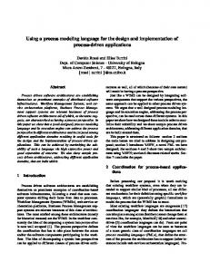
agent system has to be filled, see also [1]. In this paper we aim to bridge this gap enabling designers to build concrete multi-agent systems applications. In particular, we propose a design process that enables a designer to incrementally refine the model of the agent behavior from a high level role model toward a concrete agent architecture for adaptive behavior, in casu a free-flow architecture. In previous work, we already proposed statecharts as a formalism to describe roles, see [11]. In that work the focus was on reusing roles in different applications and the statecharts notation was extended with new concepts, such as pre-action and post-action. Although a statechart specification of agent behavior is simple to design and to understand, it is typically a static, rigid model in that it leaves little room for adaptive and explorative behavior. In this paper we revise the statechart modeling language, i.e. we refrain from considering a statechart description of agent behavior as a kind of sequence chart, but use statecharts to describe role composition and to structure related actions in roles only. To design adaptive behavior for agents, the designer needs to go through a number of subsequent design steps as depicted in Fig. 2. In the first step, the adaptive behavior is designed in a high level model making use of the role abstraction and the proposed role statechart modeling language. The diagrams of this high level model serve as a basis for structuring the free-flow tree in the next design step, resulting in a skeleton of the free-flow architecture. As the name indicates, it is a skeleton of the free-flow tree and thus it still needs to be refined by the designer. The refined free-flow architecture serves on its turn as a basis for the class diagram model in the last step of the design process. In the next section we elaborate in detail on each of the steps of the design process and illustrate them with a concrete example. Note that in practice the design process is typically not a one way pass through the indicated design steps. The designer may iterate a number of times over the different steps of the design process.
� ����� ��������
�������
��� � � � � � �
��
��� � ������ ����
� ����
����� �������
� ������ � �
�� � � ����� �
Fig. 2. Design process for adaptive behavior of situated agents
A Design Process for Adaptive Behavior of Situated Agents
3
115
A Design Process for Roles
In this section we discuss the design process for adaptive agent behavior. We start with a brief introduction of the example application. Then we zoom in and discuss the subsequent steps of the design process in detail. 3.1
Example Application
In a current research project with an industrial partner we investigate how the paradigm of situated multi-agent systems can be applied to the control of logistic machines. Traditional systems use one central controller that instructs the machines to perform jobs based on a preceding calculated plan. Increasing demands with respect to adaptability and scalability faces the centralized approach with a number of limitations. By looking at machines as agents of a situated multi-agent system, we aim to convert the centralized control system into a self-managing distributed system, improving adaptability and scalability. For the case in this paper we limit the discussion to the Automated Guided Vehicle (AGV) transport system. The AGV transport system is typically one part, yet a crucial part, of an integral logistic warehouse system. AGVs are unmanned vehicles that transport goods from one place to another. AGVs can supply basic/raw materials to a production department, serve as a link between different production lines or store goods between different processes and connect to the dispatch area. In a centrally controlled approach, the functionality of the individual AGVs is rather limited. Each AGV is provided with basic infrastructure to ensure safety. Besides, a typical AGV is able to perform pick and drop functions autonomously. The distribution of jobs, the routing through the infrastructure, collision avoidance at junctions etc. are all handled by the central control system. In the research project we apply a decentralized approach to tackle the problem of controlling the AGVs. In this paper we look at a number of basic roles for an AGV to deal with jobs autonomously. We take into account functionality for the AGV to find a job, to handle a job, to park when no more work has to be done and finally to ensure that the battery is charged in time. 3.2
High Level Model: Role Model
Before we elaborate on the design of the role model we first clarify what we mean by the role abstraction. We regard a role as an agent’s functionality in the context of an organization. Roles provide the building blocks for social organization of the MAS. Agents are linked to other agents by the roles they play in the organization. The links can be explicit, e.g. a set of agents that pass objects along a chain; or implicitly, e.g. in an ant colony a dynamic balance exists between ants that supply the colony with food and ants that maintain the nest. In the first step of the design process, the high level role model of the agents is designed. High level modeling is supported by two diagrams and one schema. The role diagram structures the agent roles and their interdependencies. We distinguish two kinds of interdependencies: roles can be related in a hierarchy and
116
E. Steegmans et al.
�������
�����
������ �� � �
��� �� ����
�� � � ���
����
��� ������
��� ���
Fig. 3. The role diagram of the AGV
roles can be related through situated commitments. The role hierarchy expresses the behavior of the agent at different levels of abstraction. A situated commitment expresses an agent’s preference of one role in relation to one or more other roles. The action diagrams structure the related actions within the roles. Finally a commitment schema defines the activation and deactivation conditions for a situated commitment. Role Diagram. The roles and their interdependencies that describe the behavior of an agent are described in a role diagram. Fig. 3 depicts the role diagram of an AGV. A role diagram consists of a hierarchy of roles of which some are related through situated commitments. A role is represented by a white oval and the name of the role is written in the oval. A role can consist of a number of sub-roles, and sub-roles of sub-subroles etc. As such the role diagram is typically composed of a hierarchy of roles. Roles at the bottom of the hierarchy are denoted as basic roles. The first role of the AGV is the Active role consisting of two sub-roles, Search, i.e. a basic role, and Work. The Work role is further split up in two sub-roles, Collect and Deliver. This latter too are two basic roles. In the Search role the AGV searches for a new job. Once the AGV finds a job it will Collect the good associated with the job and subsequently Deliver the good at the requested destination. Besides the Active role, the AGV has the Maintain role and the Park role. The AGV executes the Park role when it has no more work to do. In this role the AGV simply moves to the nearest parking place. The Maintain role ensures that the AGV keeps its battery loaded. When the energy level crosses a critical value, the AGV finishes its current job and moves towards the nearest charging station. To find its way to the charging station an AGV uses an internal gradient map. At regular time intervals all charging stations broadcast their current status. AGVs use these messages to keep their gradient maps up to date.
A Design Process for Adaptive Behavior of Situated Agents
117
��������
��� �� ������� ������
� ����
� �������
�� �������
��� ��
���� � ��� � ����� �
�� � �� ���� �
��� � ����� � �� �� �
�� �
��� �
Fig. 4. The action diagram of the Maintain role
A situated commitment is represented by a rounded rectangle and the name of the situated commitment is written in the rectangle. A situated commitment defines a relationship between one role (the goal role) and a non-empty set of other roles (the source roles) of the agent. When a situated commitment is activated the behavior of the agent tends to prefer the goal role of the commitment over the source role(s). Favoring the goal role results in more consistent behavior of the agent towards the commitment. An agent can commit to itself, e.g. when it has to fulfill a vital task. However, in a collaboration agents commit relatively to one another, typically via communication. We elaborate on situated commitments below, references that explain the concept in detail are [25][24][22]. In Fig. 3, the Maintaining commitment ensures that the AGV maintains its energy level. Since energy is vital for the AGV to function, all roles (except the Maintain role of course) are connected as source roles to the Maintaining commitment. The Activation commitment is activated when the AGV starts to work. This commitment ensures that the AGV remains active once it decides to start working. The Working commitment is activated once the AGV accepts a job. This commitment ensures that the AGV acts consistently with the job in progress. Action Diagram. Action diagrams are defined for the basic roles. An action diagram describes the structure of the related actions for a basic role. In Fig. 4 the action diagram of the Maintain role of the AGV is depicted. A state is represented by a white circle in the diagram. In Fig.4 three states can be distinguished: ToStation, Charging and Charged. Besides these states there are two special states: the initial state and the final state. The initial state, represented by a black circle, indicates the typical start state of the action sequence of the modelled role. The final state, depicted by a circle with an F written in it, indicates the typical end state of the action sequence of the modelled role. A transition connects two states with each other. A transition expresses a change of state due to the execution of an action. An action, which is added to a transition, models the functionality that must be performed by an agent to achieve a new desired state from an old state. An action is represented by a white rectangule in which the name of the action is written and which is
118
E. Steegmans et al.
attached to a transition. To fulfill the Maintain role, the AGV has to perform four different actions: follow gradient to find the charge station, and connect, charge and disconnect to charge its battery (see Fig. 4). The execution of an action may be constrained by a precondition. Only when the precondition is satisfied the attached action can be executed. A precondition is represented by a gray rectangle in which the precondition is written and which is attached to an action. In Fig. 4 the gray rectangle with not at station denotes that the AGV keeps following the gradient until it reaches the charge station. At that time the precondition at station becomes true and that enables the AGV to connect to the charge station. As long as energy level < to charge is true, the AGV keeps charging. Finally when condition energy level = charged becomes true, the AGV disconnects and that finishes the Maintain role. Commitment Schema. For each situated commitment a commitment schema is defined that describes the source roles and the goal role of the commitment as well as its activation and deactivation conditions. Activation and deactivation conditions are boolean expressions based on internal state of the agent or perceived information, or information received from messages. Activating situated commitments through communication enable situated agents to setup explicit collaborations in which each participant plays a specific role. In this paper we do not elaborate on this latter scenario, for a detailed discussion we refer to [24][22]. Fig. 5 depicts the commitment schema for the situated commitment Maintaining.
������� �� �� � �� �� ��� �
����� ������ ������� ���� ���� ����� �� ���
��������� �� ����� � � �� � ����� � �� ���� � ����������� �� ����� � � �� � ����� � ���� �� Fig. 5. The commitment schema for the situated commitment Maintaining
This commitment schema expresses that when the energy level of the AGV falls below the threshold to charge, the situated commitment M aintaining is activated. This will urge the AGV to prefer to execute the M aintain role over the Active and P ark roles. Once the battery is recharged the condition energy level = charged becomes true and this deactivates the M aintaining commitment. 3.3
Free-Flow Architecture
The role and action diagrams, together with the commitment schema serve as a basis to design the free-flow architecture in the second design step. First the
A Design Process for Adaptive Behavior of Situated Agents
119
Maintaining Activation
Active Working
Work
Search
Collect
Park
Maintain
Deliver
Fig. 6. Skeleton structure of the free-flow tree according to the role diagram of Fig. 3
high level models are used to build a skeleton of the free-flow architecture which then can further be refined. Skeleton of Free-Flow Tree. The free-flow tree describes the behavior of the agent in detail. The high level diagrams for roles and situated commitments described in the previous section serve as a basis for structuring the free-flow tree. The role structure as described in the role diagram (see Fig. 3) is reflected in the skeleton structure of the tree. Fig. 6 depicts the skeleton structure for the AGV example. Roles match to trees in the free-flow tree, sub-roles to sub-trees etc. Situated commitments on the other hand correspond to connectors that connect the source roles of the situated commitment with the goal role. When a situated commitment is activated, extra activity is injected in the goal role relative to the activity levels of the source roles. Details are discussed shortly. The action diagrams and commitment schemas enable the developer to refine the skeleton tree. Fig. 7 depicts the refined sub-tree for the Maintain role and the Maintaining commitment. States in the action diagram correspond to activity nodes in the tree. Preconditions correspond to binary stimuli connected to the corresponding nodes. Examples are the stimuli at station or connected (compare Fig. 4 and Fig. 7). Each action in the action diagram of the basic role corresponds with an action node in the tree. A number of other analog stimuli in the tree represent data in the action diagram that determines the action selection. An example is the stimulus gradient that guides the AGV to move towards the station. The activation and de-activation conditions of the situated commitments, described in the commitment schema correspond to the conditions associated with the corresponding connectors in the free-flow activity tree. Fig. 7 illustrates this for the Maintaining commitment. Refining the Free-Flow Tree. Next the developer can refine the free-flow tree, integrating all details needed for action selection. Fig. 8 depicts the refined subtree of the Maintain role and the situated commitment Maintaining.
120
E. Steegmans et al.
������ �� �
��� �� ��� � �� � � ��
����������
��� �� ��� � � � ���
������� ��� �� ���� �� �������
��� �� �������
��������� � ������
� � ����
������������
���������
������� � � �� ����������
�
�� � ������
Fig. 7. Detailed skeleton of Maintain role and Maintaining commitment
������ �����
������� ���������� �������� �����
����� ���
�������� ��������
������ ����� � � ������
�
����������
������ ����� � �������
�������
�
������ �����
������ ���� �� ����� �
� � �� ����� �
�
�
����� � ����
��������
��
���� �������
�������� � �������
��
����� ���� ���� ���� ����� ���� ���
� ����� ������ ���� �����
Fig. 8. Maintain role and Maintaining commitment after refinement
A Design Process for Adaptive Behavior of Situated Agents
121
The abstract action node follow gradient in Fig. 7 is refined towards the different moving actions of the AGV. The stimulus gradient is split up in a multi-directional stimulus. Each segment represents the tendency (based on the value of the gradient field) of the AGV to move in a particular direction. Besides, a couple of extra stimuli represent data that influences the action selection. An example is the multi-directional stimulus free that denotes in which direction the AGV is able to drive. Stimuli needed to verify the activation and deactivation condition are connected to the situated commitment. The M aintaining commitment is activated when the value of the energy level crosses the threshold value to charge. The commitment then calculates the extra activity to inject in the M aintain role. For the M aintaining commitment this extra activity is calculated as the sum (’+’ symbol) of the activity level of the Active and P ark role, i.e. the activity levels of the top nodes of these roles. As soon as the battery level reaches the threshold value charged the M aintaining commitment is deactivated and it no longer injects extra activity in the M aintain role. 3.4
Class Diagram: Free-Flow Framework
In the last design step, the refined free-flow tree is mapped onto a class diagram. For this class diagram we distinguish two parts, a f ramework and the application specific part for each hot spot that instantiates the framework. Framework. We have designed a framework [16] for the free-flow architecture and implemented it in .NET. In Fig. 9 only a part of the framework is depicted, i.e. the classes and associations drawn above the dotted line2 belong to the framework. The framework consists of a set of related classes that model the concepts of the free-flow architecture as described in the previous section. The concept of a situated commitment with its activation and deactivation conditions is modeled by the SituatedCommitment class which subclasses the FunctionNode class and which has an activationCondition and a deactivationCondition association with the SituatedCommitmentFunction class. In the free-flow architecture two kinds of stimuli are distinguished, a binary stimulus and an analog stimulus. This is modeled in the framework by the class hierarchy Stimulus, BinaryStimulus and AnalogStimulus. The concept of a link in the free-flow architecture represents a path along which activity can flow. A link is modeled as the Link class in the framework. Link has two associations, a sourceNode association with the class GenericNode and a goalNode association with the FunctionNode class. Instantiating the Framework. For a concrete free-flow tree, the generic framework has to be instantiated, i.e. the the application specific part for each hot spot has to be instantiated in the framework. The part of the class diagram under 2
For clarity, details such as the method names of the classes are not depicted. For all the details of the framework see [4].
122
E. Steegmans et al.
Fig. 9. The Maintain role and Maintaining commitment in the framework (partial)
the dotted line in Fig. 9 depicts a partial instantiation of the framework for the M aintain role and the M aintaining commitment. The situated commitment M aintaining is translated to the Maintaining class which subclasses the SituatedCommitment class of the framework. The activationCondition asso-
A Design Process for Adaptive Behavior of Situated Agents
123
ciation of the Maitaining commitment is modeled as the EnergyLevelToCharge class while the deactivationCondition association is modeled as the EnergyLevelCharged class (both are a subclass of SituatedCommitmentFunction). The link between the binary stimulus energy need and the M aintain activity node is translated to the EnergyLevelMaintain class which subclasses the Link class of the framework. The EnergyLevelMaintain class has a goalNode association with the Maintain class (a subclass of the ActivityNode class) and a sourceNode association with the EnergyLevelStimulus class (a subclass of the AnalogStimulus class). A number of other examples are depicted in the figure, but are not further explained here.
4
Conclusion and Future Work
Designing non-trivial open multi-agent systems is a challenging task. In this paper we focussed on designing adaptive behavior of situated agents. Most existing agent-oriented methodologies describe the design process independent of a particular agent architecture, however when it comes to building a concrete multi-agent application, the gap between the high level design models and the chosen multi-agent architecture has to be filled. In this paper we proposed a design process for adaptive agent behavior as part of a multi-agent oriented methodology. The design process bridges the gap between high level role modeling and a free-flow architecture for adaptive agent behavior. Starting from the results of analysis of the problem domain, the designer incrementally refines the model of the agent behavior. At the highest level, roles and their interdependencies are caught into a high level model. This model is used as a basis for designing a skeleton of the free-flow architecture. Next the skeleton is refined such that it contains all details needed for action selection. Finally, the free-flow tree is mapped onto a class diagram that serves as a basis for the implementation of the agent’s behavior. Throughout the paper we illustrated the role design process for a case study on controlling a collection of automated guided vehicles. The phased design process proposed in this paper is in line with the paradigm of Model Driven Architecture [17]. In the successive design steps, the agent behavior is specified at subsequent lower levels of abstraction, each level introducing more detail. The highest level model is independent of the architecture chosen at the medium level. Likewise, the free-flow architecture is independent of the chosen framework at the lowest design level. In future work we intend to elaborate on this vision and extend the design process towards other abstractions [15] that need to be engineered in situated MASs such as agent communication and interaction (see also [12] and [7]), and the design of the environment of the MAS.
Acknowledgements This research is supported by the K.U.Leuven research council (AgCo2) and the Flemish Institute for Advancement of Research in Industry (EMC2). We also
124
E. Steegmans et al.
would like to express our appreciation to Nelis Bouck´e for his contribution to the work presented in this paper.
References 1. M. Amor, L. Fuentes and A. Vallecillo. Bridging the Gap Between Agent-Oriented Design and Implementation. In Proceedings of the 5th International Workshop on Agent-Oriented Software Engineering (AOSE 2004), pp.1-16. 2. O. Babaoglu, H. Meling and H. Montresoret. Anthill: A Framework for the Development of Agent-Based Peer-to-Peer Systems. International Conference on Distributed Computing Systems, Vienna, Austria 2002. 3. E. Bonabeau, F. Hnaux, S. Gurin, D. Snyers, P. Kuntz and G. Theraulaz. Routing in Telecommunications Networks with Ant-Like Agents. IATA, 1998, pp.60-71. 4. N. Bouck´e. Situated Multi-Agent Approach for Distributing Control in Automatic Guided Vehicle Systems. Master Thesis, 2004. 5. R. A. Brooks. Intelligence without representation. Artificial Intelligence Journal, 1991, Vol. 47, pp.139-159. 6. J. J. Bryson. Intelligence by Design, Principles of Modularity and Coordination for Engineering Complex Adaptive Agents. PhD Dissertation: MIT, 2001. 7. L. Cabac and D. Moldt. Formal Semantics for AUML Agent Interaction Protocol Diagrams. In Proceedings of the 5th International Workshop on Agent-Oriented Software Engineering (AOSE 2004), pp.97-112. 8. G. Caire and others. Agent Oriented Analysis Using MESSAGE/UML. AgentOriented Software-Engineering II, Vol. 2222 of LNCS, New York: Springer, 2001, pp.119-135. 9. J. Ferber. An Introduction to Distributed Artificial Intelligence. Addison-Wesley, 1999. 10. M. R. Genesereth and N. Nilsson. Logical Foundations of Artificial Intelligence. Morgan Kaufmanns, 1997. 11. T. Holvoet and E. Steegmans. Application-Specific Reuse of Agent Roles. Software Engineering for Large-Scale Multi-Agent Systems, 2003, Vol. 2603 of LNCS, Springer Verlag, pp.148-164. 12. M. Ph. Huget and J. Odell. Representing Agent Interaction Protocols with Agent UML. In Proceedings of the 5th International Workshop on Agent-Oriented Software Engineering (AOSE 2004), pp.65-80. 13. M. Luck, R. Ashri and M. D’Inverno. Agent-Based Software Development. Artech House, 2004. 14. P. Maes. Modeling Adaptive Autonomous Agents. Artificial Life Journal, Vol. 1(12), 1994, pp.135-162. 15. X. Mao and E. Yu. Organizational and Social Concepts in Agent Oriented Software Engineering. In Proceedings of the 5th International Workshop on Agent-Oriented Software Engineering (AOSE 2004), pp.49-64. 16. M. E. Markiewicz and C. J. P. Lucena. Object Oriented Framework Development. ACM Crossroads Xrds7-4, 2001. See www.acm.org/crossroads/xrds74/frameworks.html 17. Model Driven Architecture (MDA): http://www.omg.org/mda/ 18. J. Odell, M. Nodine and R. Levy. A Metamodel for Agents, Roles, and Groups. In Proceedings of the 5th International Workshop on Agent-Oriented Software Engineering (AOSE 2004), pp.131-146.
A Design Process for Adaptive Behavior of Situated Agents
125
19. A. Omicini. SODA: Societies and Infrastructures in the Analysis and Design of Agent-Based Systems. Agent-Oriented Software Engineering, Vol. 1957 of LNCS, New York: Springer, 2001, pp.185-193. 20. V. Parunak. The AARIA Agent Architecture: From Manufacturing Requirements to Agent-Based System Design. Integrated Computer-Aided Engineering, Vol. 8(1), 2001, pp.45-58. 21. K. Rosenblatt and D. Payton. A fine grained alternative to the subsumbtion architecture for mobile robot control. International Joint Conference on Neural Networks, IEEE, 1989. 22. E. Steegmans, D. Weyns, T. Holvoet and Y. Berbers. Commitment-Driven Collaboration in Situated Multi-Agent Systems: A Case Study. Technical CW Report. 23. T. Tyrrell. Computational Mechanisms for Action Selection. Ph.D thesis, University of Edinburgh, 1993. 24. D. Weyns, E. Steegmans and T. Holvoet. Protocol Based Communication for Situated Multi-Agent Systems. In Proceedings of the Third International Conference on Autonomous Agents and Multi-Agent Systems (AAMAS 2004), ed. N. Jennings, C. Sierra, L. Sonenberg and M. Tambe, pp.118-126, New York, 2004. 25. D. Weyns, E. Steegmans and T. Holvoet. Towards Commitments for Situated Agents. Role-Based Collaboration at IEEE SMC 2004, International Conference on Systems, Man and Cybernetics, The Hague, The Netherlands, 2004. 26. M. Wooldridge, N. Jennings and D. Kinny. The Gaia Methodology for AgentOriented Analysis and Design. Autonomous Agents and Multi-Agent Systems, Vol. 3(3), 2000, pp.285-312.