Appl. Math. Inf. Sci. 6 No. 2S pp. 417S-423S (2012)
Applied Mathematics & Information Sciences An International Journal © 2012 NSP
@ 2012 NSP Natural Sciences Publishing Cor.
A DEVS Based Modelling Methodology — COSIM
and
Simulation
Song Xiao1, Zhang Lin1, He Dongjing1, Ren Zhiyun1 1
Science and Technology on Aircraft Control Laboratory, School of Automation Science and Electrical Engineering, Beihang University, 100191 Beijing, China Corresponding author: Email:
[email protected] or
[email protected] Received Aug. 22, 2010; Revised Sep. 1, 2011; Accepted Sep. 3, 2011
Published online: 1 January 2012
Abstract: In order to overcome some shortcomings of DEVS, this paper proposes a modeling and simulation methodology named COSIM, which is introduced from structure and behavior description of simulation system. Then the core components of COSIM, Atomic Component (AC) and Compound Components (CC) are presented with their formal definition. Moreover, COSIM specification is introduced in the form of graphic items and text formats. Finally an implementation example is given. Keywords: DEVS, System Structure, Behavior
1 Introduction Discrete Event System Specification (DEVS) is a modular and hierarchical formalism for modeling and analyzing general systems that can be discrete event systems which might be described by state transition tables, and continuous state systems which might be described by differential equations, and hybrid continuous state and discrete event systems. In DEVS, a simulation system is composed of Atomic models and Coupled models. Atomic models are expressed in a basic formalism. Coupled models are expressed using the coupled model specification — essentially providing component and coupling information. However, DEVS falls shot of addressing the following issues: Due to the rapid development of Modeling and Simulation (M&S) and software technology, some problems of DEVS have emerged. On the one hand, it is difficult to describe dynamic system behaviors of Coupled models using DEVS. On the other hand, advanced computer science technology including automata is widely used. As a result, the combined method is proposed by some researches. For example, visual state
transition chart is combined with DEVS by extending Finite State Machine (FSM). Moreover, DEVS models are white box components, whose external and internal transition functions are both defined before running. However, along with the development of simulation technology many business simulation software such as ADAMS are developed, which are black box system to users. Therefore Hybrid Input and Output Automata (HIOA) and visual state transition chart are introduced to express model behavior which treats simulation systems as black boxes. Although DEVS introduces modeling formalisms and simulation algorithms, it does not provide implementation specifications for software development. One effective way to resolve the above problems is to design and implement an M&S methodology which is named by COSIM. The main theory of COSIM is to describe a simulation system structure by Atomic Components and Compound Components, which are similar as DEVS. However, COSIM adds implementation
418
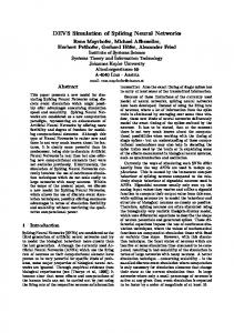
Song Xiao et al: A DEVS Based Modelling and … description of dynamic behavior using automata, which is driven by COSIM simulation engine. In sum, COSIM has three core components, Atomic Component (AC), Compound Components (CC) and Engine Component (EC) using automata based description to drive ACs and CCs. And we can see from figure 1 that EC is always part of AC and CC. Simulation Engine Component
of Atomic Component (AC) as follows:
AC inputPort , outputPort , inputEvent , outputEvent , fsm0 ,
(1)
Constraint, SemanticInterface Where: The inputPort refers to several input ports that can only receive data, which is the consumed data of AC. The formal definition of inputPort in detail is:
inputPort {(ip1 , ip2 , , ipn ) | ip1 X 1 ,
CC
ip2 X 2 , , ipn X n } Where: X i is a set of data candidates of ip i .
The outputPort refers to several output ports that can only send data, which is the produced data of AC. The formal definition of outputPort in detail is:
CC
AC
AC1
COSIM 业务组件
…
(2)
ACn
Figure 1: Overview of COSIM components
The rest of the paper we will discuss AC and CC from the perspective of system structure and present a description specification of system structure and behavior.
2 COSIM Structure Description From system engineering theory, any system is composed of structure and behavior. System structure defines what components forms a system and behavior defines how elements behave and evolve. In this section we mainly introduce the structural components which form a COSIM specified simulation system. From simulation system structure perspective, we regard the system as a number of “black boxes” (subsystems and components). The boxes connect to each other with ports and events. The basic encapsulated form of the boxes is a component. Components constitute any simulation system. The data stream and event stream of components can be implemented by Engine Component, which reads dynamic behavior scheduling and calls relevant interfaces of components temporally. Executing the simplest function in a simulation system, AC is a basic implementing component. Being the smallest reusable modules, AC cannot be separated into smaller elements (or components). Here we give the Formal Definition
outputPort {(op1 , op2 , , opn ) | op1 Y1 , op2 Y2 , , opn Yn } Where: Yi is a set of data objects of opi .
(3)
The inputEvent refers to several input event ports that can only receive event data, which often lead AC states to change. The formal definition in detail is:
inputEvent {ie1 , ie 2 ,ie N }
(4) Where: iei is a set of event data objects. The outputEvent refers to several output ports that can only send event data, which often compel the other component states to change. The formal definition of outputEvent in detail is:
outputEvent {oe1 , oe2 , oeN }
(5) Where: oei is a set of event data objects. Constraint describes the relationships among the inputPort, outputPort, inputEvent and outputEvent such as the temporal sequence, status sequence, etc. The SemanticInterface defines components’ semantic interfaces such as its professional field. fsm0 is the basic finite state machine portraying component’s behavior. The formal definition in detail is: fsm0 S , S0 , iE0 , . Where:
S {(" INIT ", A1 ), (" RUN ", A2 ),
(" STOP ", A3 ), (" PAUSE ", A4 ), (" EXIT ", A5 )}
(6)
419
Song Xiao et al: A DEVS Based Modelling and …
Where: Ai is the compelled change from S i , calling some specific simulation functions. And the formal definition for others:
S0 S ,
iE0 {evRun, evInit , evPause,
,
evStop, evTimeAdvance} (7) iE 0 inputEvent , : S 0 iE 0 S . The compelled state changes at fsm0 are shown in figure 2. START
evTimeAdvance evRun
INIT evInit
evStop
RUN
evRun
STOP
evPause
EXIT
PAUSE Figure 2: State transitions of
fsm0
fsm0 is the basic finite state machine of AC and also the top-level machine of CC, it contains the basic simulation states and sequential status transitions. In the state changes of hierarchical components, fsm0 sends event iE0 to initiate the simulation processes. According to its description of considered factors such as function, problem, information and process, a system can be decomposed into compound components and the components can be further decomposed into atomic components and compound components. Then a leveled system structure is formed, also shown in Figure 1. Moreover, the atomic components can constitute compound components; the compound components and other CC or AC can constitute a bigger CC until a system is formed. The above two different analytic methods are top-down and bottom-up. The former method is often applied in system requirement analysis and in the design phase. It mainly deduces system structure by system behavior. The latter method is to compose “big” components according to component features, then generate components or systems with specific behaviors, the method is mainly applied in the detailed design and implementation phase. CC is also composed of inputPort, outputPort,
inputEvent and outputEvent. Additionally, it includes sub-components such as ACs, other CCs, connection components among them, and interior event-driven state changes. Here we also give Formalization of Compound Component (CC) as follows:
CC inputPort , outputPort , inputEvent , outputEvent , D,{Cd | d D}, Couplings, FSM , Conta int, SemanticInterface
(8) Where: The inputPort refers to the input port of FSM. It connects with the input ports of C d . The outputPort refers to the output port of FSM. It connects with the output ports of C d . The inputEvent refers to the input event port of FSM. The outputEvent refers to the output event of FSM. D refers to the index of sub-components, and {Cd | d D} is sub-ACs and sub-CCs of CC. Couplings refer to internal component linking of CC. The formal definition for Couplings is: Couplings {cpl 0 , cpl1 ,, cpl n } ,
cpli {(Ca , oPj ) (Cb , iPk ) |
(9)
a, b D {FSM } {CC}}
Where Finite State Machine (FSM) is defined as:
FSM inputPort , inputEvent , outputEvent , fsms, Rsf
,
fsms { fsm0 , fsm1 ,, fsmn } ,
Rsf : Sij fsm j , i j , Si fsmi ,
(10)
The state of fsm0 (" RUN " , fsmi ,i0 ) is a compound state. The other state definition is same as the basic state machine of AC. fsmi ,i0 S , Sc , iE , S0 , C, .
Constraint describes the relationships among the inputPort, outputPort, inputEvent, outputEvent, Couplings and FSM, especially CC’s temporal sequence, status sequence etc. The SemanticInterface represents CC’s semantic interfaces such as its professional field. When connecting ACs and CCs to build a
420
Song Xiao et al: A DEVS Based Modelling and … simulation system, two types of link are considered, which are the data link and event link respectively. The data link is the continuously temporal matching of a data provider and a data consumer, which includes data type match, temporal sequence match and update frequency match, etc. Event link is the discontinuously temporal match of an event provider and an event consumer, which includes an event profile, an event data structure and an event time stamp, etc.
3 COSIM Behavior Description In COSIM specification, system behavior is described using automata. And in this section, we mainly introduce the method to describe component behavior. Dynamic component behavior not only includes responding to external incentive events but also generating output data and events in the process. After introducing the concepts of AC and CC, we now try to study more about state transitions and output of a simulation system. Currently, the dynamic component behavior is described using FSM of AC or CC, connecting with other sub-components by ports and events. When the external events of compound components are input to the dynamic behavior component, it analyzes the input events and generates state transformation. In the transformation it is likely to send scheduling events to other sub-components and then it transforms to a new state. When the port data of sub-component changes, its state machine will feel the data changes and generate the resolution of a guarded condition among the states. States and their transformations are basic modeling elements of system dynamic behavior. A simple state and a compound state form layered states, and the state transitions constitute system dynamic characteristics. The main triggering conditions of state transformations contain the triggering events of external input, judgment of logical time, and the changes of guarded condition triggered by the updating input ports. Action is the scheduling of AC and CC conducted by dynamic behavior components. Actions can be taken inside the states or in the process of sate transformations. This paper adopts state machine theory to carry out dynamic behavior modeling. The input and output of state machine components are shown in figure 3.
Simulation Time
State Machine
Events Variables (Ports)
Component Action Output Event
Figure 3: Input and output of state machine component
With state machine components we can clearly describe the process of a system receiving events and disposing events. So the state machine is suitable for the modeling of discrete event systems and hybrid systems. With richer descriptive semantics, visual state charts present the method of visual modeling on state machine components.
4 COSIM Specification Using discussed structure and behavior description, COSIM formal specification help domain users to model practical systems. By referencing UML graphic specification, COSIM bridges DEVS with UML behavior modeling method. The output of graphic modeling actually is model description script in the XML text, which is later parsed and used by COSIM engine to implement simulation system. 4.1 Structure Specification Table 1: Graphic items of COSIM structure specification Item Meaning Information Model Name, Index, Semantic Tag, Type, Component Domain, Version etc. Port Name, Event Event Port Object, Type, Direction etc. Port Name, Data Data Port Content, Type, Direction etc. Initialization Port Name, Data Port, Content, Type, Parameter Port Direction etc. Source Port Name, Type, Time, Type; Connection destination Port Name, Type, Time, Type.
Compatible with the above graphic expression, text specification of model structure is discussed as follows:
421
Song Xiao et al: A DEVS Based Modelling and … The start and end of model is tagged with and . Meta data of model is defined as figure 4 shows. There are four types of ports, which are Event Port, Data Port, Initialization Port and Parameter Port. Different ports form model interfaces. Here we study the ports in detail.
Figure 6: XML Schema View of Data Port
3) Initialization Port attributes are shown in figure 7.
Figure 4: Meta data of COSIM model
1) Event Port attributes are shown in figure 5.
Figure 7: XML schema view of Initialization Port
4) Parameter Port attributes are shown in figure 8.
Figure 8: XML schema view of Parameter Port Figure 5: XML schema view of Event Port
2) Data Port attributes are shown in figure 6.
Connection is important for compound models. System formal modeling specification checks connections among models to verify their validity. Furthermore, simulation engine connection management service work according to connection information defined. Model connection functions dynamic coupling pair at run-time. Simulation time of connection represent the connection information must be used with time stamp, in order to insure correct temporal logic.
422
Song Xiao et al: A DEVS Based Modelling and …
Judgment Transformation
Transition Component Model Figure 9: XML schema view of coupling connection
4.2 Behavior Specification
Sequence Chart
Life Line Incentive
COSIM behavior specification uses state chart and sequence chart to specify system behaviors. State chart can present Atomic Model behavior. State chart and sequence chart are combined to describe Compound Model behavior for several reasons. Firstly, they are designed to model a system from different perspectives. The former takes a component model as the only subject, independently portraying the responses of the model to outside incentives using states and transitions. On contrast, the latter is a graphic presentation of a scenario, portraying interactive and temporal activities among various models. Secondly, they both present dynamic behaviors of discrete event systems, while having some common elements which are used in different ways. Lastly, the former is more appropriate for description of single model’s scheduling and the latter is more suitable for presentation of various models’ temporal iterations. Table 2 shows the graphic items of dynamic model behavior specification.
Event 4.3 COSIM Application Example
Figure 10 shows graphic structure presentation of a simulation system. Figure 11 shows graphic behavior presentation of a simulation system.
Figure 10: Graphic structure presentation of a simulation system
Table 2: Graphic items of COSIM behavior
specification Chart
Item
Meaning Initial State Last State
State Chart
State
Concurrent States Figure 11: Graphic behavior presentation of
a simulation
423
Song Xiao et al: A DEVS Based Modelling and …
system
5 Conclusion A DEVS based modeling and simulation methodology, COSIM is introduced from structure and behavior view respectively. And the COSIM specification is introduced in the form of graphic items and text formats. However, due to the paper length limit we cannot fully introduce the proposed method, which we will studied more detailedly in the near future.
Acknowledgements This research was supported by grant 61104057, 61074144 and 61004089 from the Natural Science Foundation of China and National key Lab of Virtual Reality Technology and System. The authors thank the reviewers for their comments.
References [1] Barbara Zitova , Jan Flusser. Image registration methods: a survey. Image and Vision Computing. Vol.22, No.11, (2003), 977-1000. [2] Li Bohu, Chai Xudong, Zhu Wenhai, et al. Supporting Environment Technology for Collaborative Manufacturing of Complex Product, Computer Integrated Manufacturing Systems-CIMS, Vol.9, No.8, (2003), 691-697 (in Chinese). [3] B.P. Zeigler, Praehofer H, Kim T G. Theory of Modeling and Simulation, second edition. USA: Academic Press, (2000). [4] Gabriel A. Wainer, Discrete-Event Modeling and Simulation: A Practitioner's Approach. UK: Taylor and Francis Press, (2009). [5] Song Xiao, Li Bohu, Chai Xudong, Research on Key Technologies of Complex Product Virtual Prototype Lifecycle Management (CPVPLM), Simulation Modelling Practice and Theory, Vol.16, No.4, (2008), 387-398. [6] Song Xiao, Research on Key Technologies of Complex Product Virtual Prototype Lifecycle Management, Ph.D Thesis, Beihang University, (2006). [7] LI Bohu, CHAI Xudong, XIONG Guangleng, et al. Research and primary practice on virtual prototyping engineering of complex product. Journal of System Simulation, Vol.14, No.3, (2002), 336-341 (in Chinese). [8] DI Yanqiang, LI Bohu, CHAI Xudong, et al. Research
on
architecture
and
supporting
Technology
in
components based collaborative simulation virtual prototyping engineering of complex product [M]. Chinese equipment apartment simulation technology professional Team’02 academic meeting, (2003), 1937(in Chinese).
As a member of China Association of System Simulation (CASS), Song Xiao is an associate professor in Beihang University (BUAA). His research interests include system modeling and simulation and integrated manufacturing systems. Song Xiao is the corresponding author and can be contacted at:
[email protected]. Zhang Lin is a full professor in Beihang University. From 2002 to 2005 he worked at the US Naval Postgraduate School as a senior research associate of the US National Research Council. His research interests include system modeling and simulation, integrated manufacturing systems, and software engineering. He Dongjing is a M.S.E. candidate in the School of Automation Science and Electrical Engineering of Beihang University. His research interests include High Performance Computing, Parallel Simulation, Web Services, and Product Collaborative Design. He is a member of China Association of System Simulation. Ren Zhiyun is a M.S.E. candidate in the School of Automation Science and Electrical Engineering of Beihang University. Her research interests include Modeling and Simulation practice and theory, Web Services, and Product Collaborative Design.