A DFA FRAMEWORK FOR HYBRID MICROSYSTEMS Marcel Tichem\ Dafina Tanase^ 'Department of Precision and Microsystems Engineering Faculty of Mechanical, Maritime and Materials Engineering (3mE) Delft University of Technology Mekelweg 2, 2628CD, Delft, The Netherlands
[email protected] T:+31 15 2781603 ^Electronic Instrumentation Laboratory Faculty of Electrical Engineering, Mathematics and Computer Science (EEMCS) Delft University of Technology Mekelweg 4, 2628 CD Delft, The Netherlands
[email protected] T:+31 15 2786432
Abstract This paper presents a framework for Design For Assembly of hybrid microsystems. Hybrid microsystems are microsystems, mainly semi-conductor based, which offer diverse fiinctionality, and which are realised by integrating elements (die, parts) from different material and technology domains. From macro-domain mechanical products, it is known that the design of these products is of major importance for the performance of the assembly process. The paper addresses the question which aspects of assembly-oriented design are relevant for hybrid microsystems. A Design For Assembly (DFA) framework is presented, which distinguishes two main levels of design decisions: the integration approach level and the process and technology level. The framework is illustrated on the basis of a product case: an optode for medical applications.
1 Introduction Hybrid microsystems originate from two converging trends in the precision and micro mechanical engineering domain and the semiconductor domain, respectively. In the mechanical engineering domain, there is an ongoing trend for miniaturisation of specific frinctions (e.g. mechanical, optical and fluidic ftinctions). Applications can be found in consumer electronics, medical instrumentation and (opto-electronic) communication systems. To meet the miniaturisation demands, microsystem technology (MST) is an important enabler. In the semiconductor domain, microelectronics evolves in two directions: More Moore (ongoing miniaturisation, leading to nanoelectronics) and More than Moore. The latter leads to broadening of functionality on the small scale (e.g. micro-optic, micro-fluidics). Essentially this Please use the following format when citing this chapter: Tichem, M., Tanase, D., 2008, in IFIP International Federation for Information Processing, Volume 260, MicroAssembly Technologies and Applications, eds. Ratchev, S., Koelemeijer, S., (Boston: Springer), pp. 13-22.
14
A DFA Framework for Hybrid Microsystems
means that the two domains of miniaturised mechanical engineering systems and microsystems are converging, leading to new applications and product performance possibilities. This paper focuses on hybrid microsystems. As opposed to monolithic microsystems, hybrid microsystems are composed of multiple elements for the primary functions. In addition, they often combine multiple ftinctional domains; next to electronic ftinctionality, optical or fluidic functionality may be included. In hybrid microsystem production, two main steps can be identified: the wafer-based processing of die or chips and the integration of the different elements into composed systems. Next to chips, elements manufactured using other sets of techniques may also have to be integrated, e.g. optical elements made out of glass. A number of levels can be identified in the process of packaging and assembly of hybrid microsystems and the products these systems are to be integrated in, a number of levels can be identified. The level this paper focuses on is the integration of single chips (and possibly other elements) into components, i.e. the lowest levels of packaging. In hybrid microsystem integration, both technical and economic demands must be met. The technical challenge is in the handling, aligning and joining, sometimes with high (post bonding) accuracy, of small elements. The economic challenge is that this must often be done in large quantities against low cost. In the domain of microsystems, some considerable research activities are focused on exploring physical working principles, and the realisation of prototype systems for evaluation is often done in an ad-hoc manner, only considering the microsystem's functional requirements. However, large volume manufacturing would require different sets of techniques, as well as redesign of the prototype microsystems, both targeted at high volume manufacturing. This paper presents afi*ameworkfor a Design For Assembly approach for hybrid microsystems, which aims at supporting the (re)design of microsystems for volume manufacturing. More specifically, the goals of the paper are to explore the requirements for a DFA framework (Section 2), to identify the relevant design decisions to be made (Sections 3-4), and to illustrate the proposed approach on basis of a case study (Section 5). Section 6 provides conclusions and an outlook on future work.
2 DFA focus for hybrid microsystems In the design and assembly of macro-domain mechanical products and systems, it has been demonstrated that the key for optimisation of the assembly process lies in the product design activity. Through all the decisions that product designers take, the assembly process as well as the required assembly techniques are largely predetermined. This also implies that this is the phase where alternatives for product design need to be considered and evaluated from the perspective of assembly. Potential assembly difficulties need to be faced and solved during product design. This is what is referred to as Design For Assembly (DFA): design of the product from the viewpoint of optimising assembly.
M Tichem, D. Tanase
15
For macro-domain products, structured sets of design guidelines and structured product analysis tools are available for DFA. In terms of the product structure, they focus on three different levels: • Product level: structuring of a product and a product family in order to allow easy realisation of product variants and product generations. Modular product design, taking into account the type of function from a user's perspective (basic function, variant function, option) is key to this optimisation step. • Sub-assembly: structuring of a sub-assembly for efficient assembly. The main goal is to reduce the assembly content, i.e. the amount of work needed to assemble the sub-assembly or module. It is tried to reduce the part count, and to minimise the number of secondary operations like sub-assembly reorientations. • Part/connection level: optimisation of the handling and mating of parts. Part shapes and part interfaces are defined in such a way that easy handling and part alignment and joining is realised. Probably the best-known method for DFA for macro-domain mechanical products is the Boothroyd and Dewhurst DFA method [1]. The focus in their method is in particular on the sub-assembly and part/connection level as defined above. More recently, with the emergence of micro-domain products, it has been tried to adopt such methods for this new domain of products. A conclusion is that several of the rules for macro-domain products are still valid for the micro-domain. Rules that are specific for the micro-domain for instance focus on reducing (the effect of) adhesive forces. More recent research on Design For Assembly for meso and microproducts can be found in [2, 3]. Considering the type of products this research focuses on, hybrid microsystems, it is necessary to redefine what the emphasis in a DFA analysis must be, and which aspects of existing approaches can and cannot be reused. The following can be observed: • A DFA method for hybrid microsystems must consider the lower levels of system integration (chip -> component) and the assembly issues related to this level. • The design freedom for this type of systems is limited compared to macrodomain products. In macro-domain products, the product frjnctionality is a result of material and geometry choices made by the designer, and quite some design freedom exists to adapt part geometry for ease of assembly. The intimate relationship between product functionality and geometry is less dominant for hybrid microsystems. For instance, the many macro-domain rules which aim at preventing part nestling and ease of insertion are less important for the lowest packaging levels. • Integration technology is less well developed compared to macro-domain product assembly. Many techniques are still under development. DFA for traditional products was developed under the existence of known ways of assembly. Microassembly and microsystem integration is a developing field. Although quite a
A DFA Framework for Hybrid Microsystems
16
few techniques exist for micro-electronic packaging, new techniques are needed and under development for the packaging and assembly of hybrid microsystems.
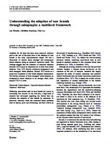
3 Structure of the DFA framework The proposed DFA framework defines the main decisions to be taken by developers of microsystems and their integration (assembly, packaging) process. Figure 1 shows the framework. Proposed microsystem design i '-11, 'J-l^ Known integration — » approaches ^1"""
' ';; Available technology
—
•
(0
Select integration approach
Design assembly process Select enabling technology
1 .1. a> o
i (Re) designed microsystem Assembly solution
Fig, 1. Proposed DFA framework
For hybrid microsystems, it is useful to distinguish two levels of design considerations: the integration approach level and the process and technology level. On integration approach level, options for the system architecture and its resulting main sequence of assembly and packaging activities is determined. Decisions on this level have a major influence on the efficiency of the assembly process. This level is detailed in Section 4. Once the main integration approach is chosen, the assembly process and the enabling technologies need to be detailed. The assembly process is the series of transformations by which (a) die/part(s) is (are) brought from an initial state, defined by the manufacturing process, to a final state, i.e. the final position and fixation in the product. This needs to be done for each die/part to be assembled. The first step to be done is the design of this assembly process. Secondly, suitable techniques for each of the operations (i.e. the transformations) have to be chosen. This includes transfer, alignment and bonding of the elements. The process and technology level is not further detailed in this paper.
M Tichem, D. Tanase
17
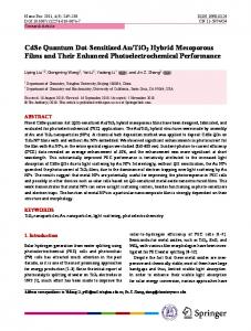
4 Architecture level Figure 2 shows the main approaches to integration. Monolithic integration means that functionality is realised in one chip, using a series of processing steps. As the diversity in functionality increases, this approach usually becomes more difficult. Also, the advantages of using the optimal technology for each function may lead to the choice of a hybrid approach. Finally, reducing the time-to-market may be the decisive criterion; developing a monolithic chip may require a long development lead time.
Integration approaches
n: Monolithic integration
Hybrid integration
X Single die/part integration
Layer-2-layer integration
On-board Integration
Fig. 2. Overview integration approaches
From a part-logistic view, only a limited number of principally different hybrid integration approaches exists. Single chip/part integration. Microsystems are realised by the integration of individual chips and parts. The main advantage of this integration approach is its high flexibility in terms of product designs that can be realised. The disadvantage is that each operation is single part oriented, thus increasing the integration effort. This is in contrast to the wafer-oriented approach in front-end processing of the wafers. Layer oriented integration. Microsystems are realised in batch approaches, by integrating layers containing different types of functionality. The best known approaches are wafer-to-wafer bonding and Wafer Level Packaging (WLP). Individual microsystems are obtained by dicing the bonded stack of functional layers. This approach improves the assembly efficiency compared to the first option mentioned, but it limits the design freedom of the microsystem designer. Also, the technology for this approach is less developed. On-board integration. The essence of this integration approach is that a toolbox of components is realised, each one having a certain function, which can be combined in arbitrary combinations on a substrate by standardised interfaces. The substrate may also support interconnection of the components: a circuit board. A well-known example is Surface Mount Technology in the context of electronic printed circuit board (PCB) assembly, which has been developed for easy inte-
18
A DFA Framework for Hybrid Microsystems
gration of electronics. In the context of micro-optical systems, Silicon Optical Bench (SiOB) technology is an enabler for this integration approach. The standardisation helps in realising robust integration processes, and reuse of processes and equipment. For a given microsystem design, a suitable integration approach needs to be selected. In some cases, a series of integration approaches needs to be defined, showing the step-wise development of the microsystem and/or its integration approach. This is often specified in terms of a roadmap for the development of the microsystem. The following aspects are identified in defining a microsystem roadmap and a progressing integration process: • Ongoing microsystem miniaturisation. The need for smaller system dimensions (e.g. area or thickness) may require making new choices. For example, instead of electrically interconnecting microsystems using wire bonds, flip chip technology may have to be chosen to educe system area. • Increased integration. To bring a microsystem design to the market, one may first choose to integrate the system on the basis of adding individual components. At the same time, a development may be started to realise a monolithic integration of the different chips (fi-om System in Package, SiP, to System on Chip, SoC). • Changing production volumes. For example, the first prototypes of a new microsystem, used for evaluation and demonstration purposes, will usually be produced in low volumes, for which technology investments are economically not affordable. Later, the focus may shift towards higher volume production, necessitating a redesign of the microsystem and its integration process. Investments in technology (development) may be affordable for this new situation.
5 Case-based illustration To illustrate the presented DFA framework, the case shown in Figure 3 is considered. The so-called optode is part of an implantable system to be used for photodynamic therapy. Another medical application which also makes use of optodes is tissue viability monitoring after colon surgery. For both medical applications research is currently being performed at the TU Delft, DIMES and the Erasmus Medical Centre, Rotterdam. It is beyond the scope of this paper to describe these medical applications in more detail or to explain the entire fiinctionality of such measurement systems, but for now let us have a look at the optode. For more information on the application and the optode see [4]. The optode is a combination of light sources and detectors with suitable signal conditioning and read-out electronics. For these medical applications, the light sources are chip-form LEDs (Light Emitting Diodes) and the light detectors are photodiodes. While the photodiode and the read-out electronics can be integrated on a silicon wafer using IC (Integrated Circuits) technology, the LEDs are supplied as
M Tichem, D. Tanase
19
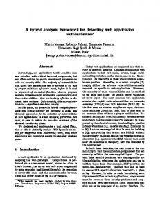
stand-alone chips, which need to be assembled on the silicon wafer. Therefore, the focus in this case study is on the assembly of the LED chips. Figure 3a shows only two of the LED chips, but different configuration of optodes can be used depending on the requirements of the medical application. For example, for photodynamic therapy with some advanced monitoring techniques, 4-6 LED chips need to be assembled, each one emitting at a certain wavelength. The size of one LED chip is approximately 200 x 200 |im, resulting in an optode surface area of approximately 1 x 1 mm. As an initial step, a number of prototype optodes were fabricated and the LED chips are being manually placed on the silicon wafer, so that first technical and clinical tests can be performed. Eventually, the system may have to be produced in millions per year, necessitating an efficient assembly process. It is this future production scenario this case study focuses on.
a)
b)
c)
Fig. 3. The optode system: a) overview, b) LED chip considered in the paper, c) polymer on top of the optode chip for reflecting the light to the photodiode.
In order to obtain the functionality for which it was designed, the optode system requires that the LED chips are assembled and electrically interconnected. An LED chip is considered which electrical connections (anode and cathode) are on opposite sides, see Figure 3b [5]. Other configurations for the electrical connections of the LED chip also exist, but for the sake of simplicity those are not considered in this discussion. Furthermore, it is also important to know that the optode system as shown in Figure 3a is to be covered with a polymer, see Figure 3c. The polymer has two functions: it is either used for final packaging of the sensor system or as a gas sensitive membrane.
5.1 Integration approach level As already indicated above, monolithic integration of the LED chips with the optode chip is not an option. LED chips are standard catalogue elements, produced in very high quantities. Hence, clearly a hybrid integration approach is chosen. Integration on basis of assembling individual LED chips one by one can certainly be expected to be feasible. The LED chips can be kept in their manufactured order, so that locations of individual LED chips are known, thus preventing an organisation (chip feeding) step. Two options exist: the LED chips are either assembled before or after dicing and singulating the optode chips. This either results in
20
^ DFA Framework for Hybrid Microsystems
assembly of single LED chips to the optode wafer or to assembly of single LED chips to single optode chips. The total effort in placement will approximately be identical. The advantage of the chip-to-wafer option is that subsequent processes may still be carried out on wafer level. In this case this would mean that it is worthwhile to investigate whether the electrical interconnections and the adding of polymer can be performed on wafer level. The layer-to-layer integration approach is worth to investigate for improving the efficiency of the LED chip assembly process. This would require reorganisation of the LED chips. In their manufactured state, the LED chips are contained in a wafer structure, but the pitch between the LED chips does not match to the required position on the optode wafer. Finally, an integration approach on basis of standardisation is technically possible. For many applications, the manufactured LED chips are packaged in to 1^* level components (then referred to as LEDs). This is a standard process. Such LEDs may than be added by standard Surface Mount Technology on the optode chip using pick and place processes and solder reflow. The optode wafer needs to be prepared for this. However, an LED has considerably larger dimensions than an LED chip, so that integrating larger numbers of LEDs (4-6) within the optode chip area of approximately 1x1 mm is not possible anymore. This option is therefore not considered from now on. Figure 4 summarises the three remaining main hybrid integration approaches for this case.
Fig. 4. Summary of options for the main integration approach: single LED chip to optode wafer (1), single LED chip to single optode chip (2), reorganisation of LED chips on some kind of carrier, followed by batch transfer to optode wafer (3)
5,2 Process and technology level The integration approach is the basis for defining the assembly process, i.e. the sequence of operations to bring the LED chips to the optode chips. For Options 1 and 2 (see Figure 4), pick and place solutions for the handling of LED chips need to be selected. It can be expected that this is technically feasible. Option 3 requires some form of LED chip reorganisation. One option the LED chip supplier indicated is that changing the pitch between the LED chips is possible by using stretchable foils. After manufacturing and dicing of the LED chips, they are transferred to a stretch-
M Tichem, D. Tanase
21
able foil which is stretched in two perpendicular directions to change the pitch between the LED chips. If larger pitch changes are needed, this process may be repeated several times, transferring the LED chips to a new unstretched foil between each step. The supplier indicated that the required pitch between LED chips of approximately 1 mm with sufficient accuracy is feasible with this approach. A challenge which then needs to be faced is the massive transfer of all LED chips to the electrical contacts on the optode wafer. This is not investigated further in the case study. An issue that remains is realising the two electrical interconnections between LED chip and optode chip. One connection can be realised by solder reflow. The other connection, however, needs more attention. Three techniques were identified, see Figure 5a. The first option is to apply a wire bond. The disadvantage is that after this step the optode needs to be covered by a polymer, and the wire bond may break due to the adding of the polymer. This solution is not considered to be sufficiently robust. A second option is to build an electrically connecting bridge by means of a series of deposition steps, see Figure 5b. Each step would require a mask, and the mask alignment is critical for creating a good connection. This deposition process is expensive; on the other hand, in this way connections can be made on wafer level, rather then for each LED chip individually. The bridges are much ore robust than the thin wire bonds. The third option uses a glass wafer, in which electronic leads are processed using lithographic techniques. This would require one mask. After processing the electronic leads, the glass wafer is bonded with the wafer containing optode chips, thus batch-wise creating electrical interconnects. The consequence is that in the eventual system, there will be a glass chip between the optode chip and the polymer. It is assumed that the intermediate glass layer will not affect the optical performance of the system, but this needs careful investigation.
a)
b)
Fig. 5. a) Options for the electrical interconnects (top to bottom: wire-bond, bridge, glass wafer with electric leads); b) Process sequence for creating a bridge by a series of deposition steps.
After this step the case study was concluded, although a final decision on the integration approach and the technologies to be chosen could not be made. Further detailed analyses and experiments on various technical options are needed to allow such a choice to be made. A major advantage of applying the DFA approach to the
22
A DFA Framework for Hybrid Microsystems
described case was that it raised many issues which the microsystem designers were not considering at the moment, but which helped them in making well balanced decisions, both for the current prototype microsystems and for the future massproduced microsystems.
6 Conclusions A DFA framework for hybrid microsystems is proposed, which distinguishes two levels of decision making for designers of such systems: the integration approach level and the assembly process and technology level. The case study shows that it is indeed possible to use these levels of thinking in defining an integration solution for hybrid microsystems. The second conclusion is that such an approach supports the consideration of future production scenarios of the microsystems under development in an early phase of their design.In future work the proposed framework will be tested and further detailed on basis of other case studies. A more fundamental approach to defining the DFA framework is needed. It is expected that with the increasing importance of hybrid microsystems, such DFA methods will become essential for their successful market introduction.
Acknowledgements This research is part of the Delft Centre for Mechatronics and Microsystems (www.dcmm.tudelft.nl) and is financed in part through the MicroNed programme and the MEMPHIS programme. MSc student Ing. R. Ooms is acknowledged for his contribution to this work.
References [1] [2]
[3]
[4]
[5]
G. Boothroyd, P. Dewhurst, Product design for assembly, 1989 T. Salmi and J. Lempiainen, First Steps in Integrating Micro-Assembly Features into Industrially used DFA Software, In: Precision Assembly Technologies for Mini and Micro Products, S. Ratchev (ed.), Proceedings of IPAS 2006, February 19-21, 2006, Bad-Hofgastein, Austria, pp. 149-154 C. Tietje, S. Ratchev, Design for Microassembly - A Methodology for Product Design and Process Selection, Proceedings of the 2007 IEEE Intemational Symposium on Assembly and Manufacturing (ISAM), Ann Arbor, Michigan, USA, July 22-25, 2007 E. Margallo-Balbas, J. Kaptein, H.J.C.M. Sterenborg, P.J. French, D.J. Robinson, Telemetric Light Delivery and Monitoring System for Photodynamic Therapy based on Solid-State Optodes, Proc. of Photonics West - BiOS 2008 (accepted) www.cree.com, CPR3DE Rev. -, Cree® UltraThinTM LED - Data Sheet CxxxUT200-Sxxxx