A Diagrammatic Tool for Representing User Interaction in UML Patrícia Vilain1,2 , Daniel Schwabe1 , Clarisse Sieckenius de Souza 1 1
Depto. de Informática, PUC-Rio, Rua Marques de São Vicente 225 Rio de Janeiro, RJ 22453-900 Brazil {vilain, schwabe, clarisse}@inf.puc-rio.br 2 Depto. de Informática e Estatística, UFSC, Campus Universitário Florianópolis, SC 88040-900 Brazil
[email protected]
A b s t r a c t . The UML suggests the employment of use cases for capturing the requirements and for specifying the interaction between the users and the system being modeled. Use cases are easily understood by users since they are essentially textual descriptions, but lack the precision and the conciseness accomplished by the other diagrammatic tools of UML. Besides, there is no systematic method that helps the designer to obtain such UML diagrams from a set of use cases. In this paper we present a diagrammatic tool to represent the users/system interaction called user interaction diagram (UID). UIDs have proven to be a valuable tool to gather requirements since they describe the exchange of information between the system and the user in a high level of abstraction, without considering specific user interface aspects and design details as in other UML diagrams. We show how UIDs can be incorporated into the requirements and analysis workflows of the Unified Process for software development.
1 Introduction Interaction is the communication activity that takes place between the user and the system [7]. From the user-system interaction, it is possible to identify the information manipulated by the system and the functionality that the system must offer. Thus, the specification of the user-system interaction is fundamental to the development of the system, mainly for requirements gathering. Different from the interaction that is the basis of this study, the interaction in the Unified Modeling Language (UML) is seen as the exchange of messages between the objects of the system [1]. So, the UML diagrams representing the interaction, such as the sequence diagrams, collaboration diagrams, statechart diagrams, and activity diagrams, are more appropriately used in the design phase. In requirements gathering, the UML suggests the employment of use cases to model user interaction. Use cases were defined as different ways of using the system [4] [5]. They deal only with the interaction between the user and the system or the information perceptible by
Patrícia Vilain et al.
the user, and they do not deal with the internal aspects of the system. Use cases have gained wide acceptance, and are used to specify the software requirements as well as the basis for the development cycle, including the analysis, design, implementation and testing activities [4] [6]. Although other approaches for requirements gathering employ use cases [2] [9], this may not be the best tool for this purpose. Use cases employ textual descriptions, which are unwieldy when used in a validation process with users, mainly because of the lack of precision and conciseness. Graphical notations, on the other hand, do not suffer from these shortcomings, and are well suited for requirements gathering. However, we are not aware of any graphical technique that represents the interaction specified in use cases independently of design aspects. We propose a diagrammatic modeling tool, User Interaction Diagrams (UID), to represent the interaction between the user and the system. UID is a tool used mainly to support the communication between the designer and users in requirements gathering. In addition, in the analysis activity UIDs also serve as input for obtaining the class diagram. Also, we propose an extension of Unified Process [4], where the UID and the guidelines to obtain the class diagram from it are incorporated in the requirements and analysis workflows. In this proposal, requirements are expressed as a powerful combination of use cases and UIDs, which are also employed as validation tools during requirements workflow. Thus, we can have increased confidence that the information represented in the class diagram will be correct and complete. The UIDs presented in this work are taken from a case study about an online shop that sells CDs. In this case study, of the six people participated, five regularly navigate the internet and sometimes shop online and only one has never used the internet. This case study produced 14 use cases and 14 UIDs. The remainder of paper is organized as follows. Section 2 presents the user interaction diagram. Section 3 shows how to define UIDs from use cases. Section 4 presents the rules to determine the class diagram using as basis the UIDs. In section 5, an extension of the Unified Process is proposed and section 6 highlights our conclusions.
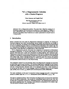
2 User Interaction Diagrams A user interaction diagram (UID) represents the interaction between the user and the system. This diagram describes only the exchange of information between the system and the user, without considering specific user interface aspects. It can be seen as the interaction information that is textually described in a use case. When we specify a UID, we do not worry about the difference between navigation interaction and interface interaction. Next, we present some examples of UIDs. The complete notation of the UID is shown in the appendix. Fig. 1 shows the UID that has been defined to represent the interaction in the task Selection of a CD based on a given title.
A Diagrammatic Tool for Representing User Interaction in UML
title or part of the CD’s title
…CD (title, artist’s name, year, price, availability, album cover, country, type of music and record company) 1..N (added to the shopping basket)
F i g . 1 . Selection of a CD based on a given title: UID
The ellipses represent the interaction between the user and the system. The interaction begins with the ellipse that has the arrow without a source. In this example the user must enter the title of the CD, denoted by a rectangle with a continuous border. After the user enters the title of the CD, the system presents the set of CDs that combine with the user’s entry. The results of each interaction which causes processing in the system should be represented as a separate ellipse, connected to the first interaction by an arrow. In the example, since the presentation of the set of CDs implies processing in the system, the resulting set is represented in another interaction that is connected to the previous by an arrow. A set of CDs is represented by ellipsis in front of the set name (…CD (title, …) in the example). For each CD shown by the system, the following data items are given: title, artist’s name, year, price, availability, album cover, country, and record company, shown within parenthesis next to the item’s name. From this last interaction, it is possible to select 1 to N CDs and execute the operation of adding them to the shopping basket, which is represented by the line connected to the text 1..N (add to the shopping basket) with a black bullet in one end. Fig. 2 shows the UID that has been defined to represent the interactions in the task Selection of a CD based on the type of music. In the first interaction in the example, the system presents a set of types of music, represented by the label …Type of music. After this interaction, the user must select one type of music followed by the choice of one of the following options: artists, all CDs, suggestions. The selection of a single type of music is represented by the number 1 attached to the outgoing arrow. If the user selects the option artists, then the interaction that shows the set of artists (for the chosen type of music) occurs. Following this interaction, the user must select one artist and the system shows the CDs related to this artist. Once more, the set of CDs related to the chosen artist is presented in a separate interaction. If the user selects the option suggestions, then the system shows the CDs that are recommended for the chosen type of music. If the user selects the option all CDs, then the system shows all CDs under the chosen type of music. For each CD shown in the three situations the following data items are given: title, artist’s name, year, price, availability, image cover, country, and record company.
Patrícia Vilain et al.
1 (artists)
…Type of music
…Artist
1 (all CDs) 1
1 (suggestions) Type of music X
…CD (title, artist’s name, year, price, availability, album cover, country and record company)
1..N (added to the shopping basket)
F i g . 2 . Selection of a CD based on the type of music: UID
Fig. 3 shows the UID that has been defined to represent the interaction in the task Buying the selected CDs. password check credit card
air sea express
cash credit
name Phone number delivery address
billing address
(confirm)
e-mail order number credit card
F i g . 3 . Buying the selected CDs: UID
In the first interaction the user may enter his password. This data item is optional and is represented by a rectangle with a dashed border. If the user enters a valid password the second interaction does not occur. Thus, this interaction is represented by a dashed border as well. If the second interaction occurs, the user must enter the mandatory data items, namely name and delivery address, and the optional data items, phone number, billing
A Diagrammatic Tool for Representing User Interaction in UML
address, e-mail, credit card. After the user enters at least the mandatory data items, the third interaction occurs. In the third interaction, the user must select the payment by check or credit card, and the shipping method, namely air, sea or express. After the user enters these data items, the user can execute the operation confirming the buying, which is followed by the system returning the order number, represented in another interaction.
3 From Use Cases To User Interaction Diagrams According to UML, the realizations of use cases can be specified by interaction diagrams, collaboration diagrams, and statechart diagrams [1]. However, the specification of use cases using these techniques is attractive to the design. In the requirements gathering, we propose to use UIDs to represent the use cases. UIDs do not interfere with the use of dependency, generalization and association relationships among use cases. For each use case, a UID is defined. To do this, the sequence of information exchanged between the user and the system is identified, and organized into interactions. The identification of this information is very important because it is the basis for the definition of the UID. In this section, we present a method to map a use case to a UID. To exemplify the application of this method, we show the mapping of the use case Selecting a CD based on a given artist’s name into a UID. Use Case Selecting a CD based on a given artist’s name: The user enters the name of the artist or part of it. He can inform the year or period of the CD being sough if he wants to. The system returns a set with the names of the artists matching the entered value. The user selects the artist of interest. The system returns a set with the CDs of the artist. For every CD found, the title, name of the artist, year, price, availability and image of the album cover are shown. If the user wishes to buy more than one CD, he selects the CD(s) and adds it (them) to the shopping basket to perform the purchase later (use case Purchase).
Phase 1. First, we analyze the use case to identify what information is exchanged between the user and the system. Generally these data items are represented by nouns. It is also important to identify which data items are given by the user and which are returned by the system. In the example, we can identify the following information exchanged between the user and the system: name of the artist or part of the name (user), the year or period of the CD being sought (user); a set with the names of the artists matching the entered value (system), the artist of interest (user); a set with the CDs of the artist, for every CD found, the title, name of the artist, year, price, availability, and image of the album cover (system).
Patrícia Vilain et al.
P h a s e 2 . After identifying the exchanged information, we have to split the data items into interactions. Data items are placed in the same interaction, unless they require processing by the system before being presented; in such cases they are placed in another interaction. Next, we try to place the subsequent data items in this interaction, and so on. In the example, the data items identified in the previous phase are split into interactions. We begin with the name of the artist or part of it data item, which is placed in the first interaction of the UID. The next data item exchanged, the year or period of the CD sought, given by the user, does not require processing by the system, so it can be placed in the same interaction as the previous data item. Since the next data item exchanged, set with the names of the artists, is returned by the system after processing a query to the artists database, it is placed in a second interaction. The next data item exchanged, the artist of interest, requires the system to verify the selection of an artist given by the user. Thus, it will be shown in the third interaction. The last data items (the title, name of the artist, year, price, availability, and image of the album cover) are returned by the system in the same processing as when selecting the artist. So, they are also placed in the third interaction. Phase 3. The data items given by the user and returned by the system must be distinguished. Mandatory data items given by the user are placed into rectangles with a continuous border and the optional data items are placed into rectangles with a dashed border. The data items returned by the system is placed directly in the interaction, without rectangles around them. The data items that are associated to an element are placed inside parenthesis and the set of elements is represented by ellipsis before the set’s name. Continuing the example, the data items placed into interactions are distinguished. In the first interaction, since the name of the artist or part of it data item is mandatory data entered by the user, it is placed inside a rectangle with a continuous border. The the year or period of the CD sought data item is optional, so it is represented inside a rectangle with a dashed border. In the second interaction, since the set with the names of the artists data item is returned by the system it is placed directly in the interaction preceded by an ellipsis. In the third interaction, despite the fact that artist of interest data item depends on the user selection, it is presented by the system, and therefore it is represented directly in the interaction. The set of CDs is also represented in the interaction prefixed with an ellipsis. The other data items are related to each CD, so, they are placed within parenthesis next to the CD. Fig. 4 presents the first, second and third interactions with their data items. Phase 4. The interactions are connected by arrows. It is possible to connect one interaction to two or more other interactions, which represents that from one interaction there are several alternative interactions and the chosen interaction depends on information entered by the user. When the change of the interactions is the result of an element selection, the number of selected elements is attached to the arrow, and the
A Diagrammatic Tool for Representing User Interaction in UML
source of this arrow is the set from which the selected elements are taken. The initial interaction always has an arrow without source. Artist’s name
name or part of the artist’s name
…Artist
year
Artist’s name
…CD (title, year, price, availability, album cover)
F i g . 4 . Use case Selecting a CD based on a given artist’s name: interactions and data items
In the example, since the second interaction occurs after all the data items in the first interaction have been entered, the source of the arrow connecting the first interaction to the second interaction is attached to the whole interaction. The third interaction occurs after the user has selected exactly one artist, so the arrow connecting the second and third interactions has the number 1 attached to it, and its source is the set of the artists (and not the entire interaction). P h a s e 5 . The operations performed against the data items must also be identified. They are generally represented in the use cases by verbs. An operation is represented in the diagram by a line with a bullet. If after the execution of the operation another interaction occurs, then the operation is represented attached to the arrow instead of the line. In the example, the last information presented in the use case is an operation, the user can select one or more CDs and include them in the shopping basket. This operation is represented by a line with a bullet connected to the set of CDs. The number of CDs selected and the operation are placed next to the line. The name of the operation is placed inside parenthesis. Phase 6. Non-functional requirements are not specified in UIDs. Although use cases do not specify these requirements, sometimes a non-functional requirement can appear. In this case it is maintained attached to the UID as text. Fig. 5 represents the complete UID.
Patrícia Vilain et al.
Artist’s name
name or part of the artist’s name
…Artist year
1
Artist’s name
1..N (added to the shopping basket)
…CD (title, year, price, availability, album cover)
F i g . 5 . Use case Selecting a CD based on a given artist’s name: UID
4 Specifying the Class Diagram The class diagram is defined from the UIDs according to the following rules: 1. For each UID define a class for each element, set element and specific element. For each defined class, assume the existence of an identifier attribute OID. 2. For each data item of the set elements that appears in each UID, define an attribute according to the following: • Verify if the data item is functionally dependent1 on the attribute OID in each class, i.e., if OID → data items. Verify if the data item is not transitively dependent2 on the OID. If these conditions are satisfied, then the data item must become an attribute of the class. The verification should preferably begin with the class that represents the set, because there is a higher probability that this data item will be an attribute of this class. • Verify if the data item is functionally dependent on the attribute OID of two or more different classes and if the data item is not transitively dependent on the OIDs. If these conditions are satisfied, then the data item must become an attribute of a relationship between the classes. 1 Defined in [3] as "A functional dependency, denoted by X → Y, between two sets of attributes X and Y that are subsets of R specifies a constraint on the possible tuples that can form a relation instance r of R. The constraint states that, for any two tuples t 1 and t 2 in r such that t 1 [X] = t 2 [X], we must also have t 1 [Y] = t 2 [Y]. This means that the values of the Y component of a tuple in r depend on, or are determined by, the values of the X component; or alternatively, the values of the X component of a tuple uniquely (or functionally) determine the values of the Y component. We also say that there is a functional dependency from X to Y or that Y is functionally dependent on X." 2 Defined in [3] as "A functional dependency X → Y in a relation schema R is a transitive dependency if there is a set of attributes Z that is not a subset of any key of R, and both X → Z and Z → Y hold."
A Diagrammatic Tool for Representing User Interaction in UML
3. •
•
4.
• • 5.
• • • 6. 7.
8.
For each data item entered by the user, represented by an single rectangle, define an attribute according to the following: Verify if the data item is functionally dependent on the attribute OID in each class, i.e., if OID → data items. Verify if the data item is not transitively dependent on the OID. If these conditions are satisfied, then the data item must become an attribute of the class. The verification should begin preferably with the class that represents the set, because there is a higher probability that this data item be an attribute of this class. Verify if the data item is functionally dependent on the attribute OID of two or more different classes and if the data item is not transitively dependent on the OIDs. If these conditions are satisfied, then the data item must become an attribute of a relationship between the classes. For each attribute that appears in a set different from its class, define a relationship between its class and the class representing the set. If the attribute class is not related to the class representing the set, then verify if the attribute class is related to the class of another attribute present in the set. It is also necessary to verify if this resulting relationship is semantically correct (i.e. if it makes sense in the domain being modeled). If the attribute is a set, then the maximum cardinality of the attribute class is N. If the attribute is a single data item, then the maximum cardinality of the attribute class is 1. If the attribute is optional, represented by *, then the minimal cardinality of the attribute class is 0. For each interaction flow (represented by an arrow), if there are different classes in the source interaction and the target interaction, define a relationship between these classes. It is also necessary to verify if this relationship is semantically correct (i.e. if it makes sense in the domain being modeled). If N elements were selected in the source interaction, then the maximum cardinality of the source interaction class is N. If a set of elements was returned in the target interaction, then the maximum cardinality of the target interaction class is N. If the element or set of elements returned in the target interaction are optional, represented by *, then the minimal cardinality is 0. For each operation that appears in the UIDs, verify if it is an operation of the corresponding class. For each class that remains without attributes, verify: if there are attributes that have not been defined for the class, then include them; if the class was modeled as attribute of another class, then remove the class; if the class can be modeled as a relationship role, then remove the class. At the end of the process, do the necessary adjustments in the resulting class diagram, for instance, identify generalizations and missed relationship cardinalities.
We next show some steps of the definition of the class diagram synthesized from the UIDs in the example.
Patrícia Vilain et al.
Step 1: Definition of the classes. In each UID, a class was defined for each element, set element and specific element. The following classes were identified for each use case: CD (use cases 3, 4, 5, 6, 7, 8, 9, 10, 11, 12, 13) Song (use cases 1, 3, 4, 5, 6, 7, 8, 9, 10, 11, 13) Artist (use cases 4, 7) Type of music (use case 7) Composer (use case 10) Shopping Basket (use case 12) Purchase (use case 2)
Step 2: Definition of the attributes. The following attributes were identified from the information of the set elements of the UIDs: CD: title, year, price, availability, image cover, country, copies, price-offer. Song: title, time, lyrics. Artist: name. Type of music: name. Composer: name. Shopping Basket: quantity. Purchase: -
The following attributes were identified from the information entered by the users: CD: title, year. Song: title, sample. Artist: name. Type of music: Composer: name. Shopping Basket: Purchase: payment-option, payment-plan, delivery-option, address, rcv-email, rcv-ads.
Step 3: Definition of the relationships. The following relationships were identified from the attributes belonging to distinct classes but that appearing as information of the same element: Composer - Song CD - Artist CD - Shopping Basket CD - Type of music CD - Song Song - Artist
The following relationships were identified from the different classes presented in the source and target interactions: CD - Composer CD - Song CD - Artist Artist - Type of music
Step 4: Definition of the operations. The following operations were identified from the UIDs: CD: add to basket. Song: listen to sample.
A Diagrammatic Tool for Representing User Interaction in UML Artist: Kind of music: Composer: Shopping Basket: Purchase: -
Fig. 5 shows the class diagram that results from the first four steps: Composer name Shopping Basket quantity
Purchase payment-option payment-plan delivery-option address rcv-emails rcv-ads
CD title year price availability album cover country copies price-offer add to basket
Song title time lyrics sample listen to sample
Artist name
Type of music name
Figure 5 - Final resulting class diagram
5 Interaction in the Software Development In this section, we propose an extension of the Unified Process to include the UID and the definition of the class diagram from UIDs. This extension is applied specifically to the Requirements and Analysis workflow.
5.1 Unified Process The application development according to Unified Process [4] is divided into several cycles. Each cycle results in a product and is composed by four phases: inception, elaboration, construction and transition. Over these phases, five workflows take place: requirements, analysis, design, implementation, and test. In the Requirements, user and customer needs are identified and then they are specified as use cases. In the Analysis, use cases are refined as collaborations among classes. These classes are identified based on the use cases. Next, in the Design, use cases realizations are defined and the classes are designed considering implementation aspects. So, the designed classes are implemented as a set of components. Finally, in
Patrícia Vilain et al.
the Test, it is verified if the system implements the functionality described in the use cases. In the Requirements, the actors must first be identified. Then, for each actor, the use cases he plays are defined. User-interface prototypes can also help to gather the requirements. To do this, after the logical user-interface designs have been done, the physical user-interface designs are created. These user-interfaces specify the interaction between human actors and the system. If necessary, prototypes can be developed for some physical user-interface. In the Analysis, the classes and associations necessary to realize the use case are suggested. The entity classes, boundary classes and control classes are defined through the examination of the description of each use case. A collaboration diagram is also defined based on these classes and associations.
5.2 Extending the Unified Process Our extension makes some modifications only in the Requirements and Analysis. In the Requirements, we identify the actors and specify the use cases as in the Unified Process. But instead of defining user-interface designs, we specify a UID for each use case. These UIDs are used together with use cases to validate the requirements. Thus, we do not need to define a user-interface that may have to be modified after the Design, breaking the expectation the users will have developed over the user-interface of the system. In fact, it is too early in the development process to commit to any particular interface design. In the Analysis, the entity classes are defined using the guidelines specified in the section 4. We can complete the resulting class diagram analyzing the use-case description. The boundary classes and control classes can be defined as in the Unified Process. For each human actor, entity class, and external system actor, one boundary classes is defined. For each use case, it is necessary to verify if one or more control classes are required. The attributes of boundary and control classes can be gathered as in the Unified Process, looking at the entity classes and their attributes. To finish the Analysis, the collaboration diagram is defined as in the Unified Process. The succeeding workflows occur in the same way as the Unified Process workflows.
6 Conclusion We have presented the UIDs, a graphical notation that represent the interaction between the user and the system. They were proposed to be used in a higher abstraction level, without concern over user interface and design details. These diagrams are used to validate use cases and constitute the basis for the definition of the class diagram. The UIDs presenting the same interaction sequence, but with distinct information, can be represented as a single parameterized use case. Parameterization of UIDs facili-
A Diagrammatic Tool for Representing User Interaction in UML
tates validation. The designer carries on discussions with the users based on parameterized UIDs instead of discussing several similar UIDs one at a time. When necessary, the designer refers to the particularities of each individual UID. In this work, we have also proposed guidelines to define the class diagram from the UIDs. Some of these guidelines are based on the very know concept of functional dependency. Despite the resulting class diagram need some adjustments, it is defined based on accurate steps. UIDs can be used to gather the requirements in any software methodology. Here, we have presented how to use UIDs in the Unified Process. We have shown the proposed extensions in the Requirements and Analysis workflows to support UIDs and the definition of the class diagram. UIDs and the specification of the class diagrams presented in this work are being used as the basis of a method for gathering requirements and achieving the conceptual design of web applications [11]. This method emphasizes the importance of modeling user interaction and involving users in this process. It starts by capturing the requirements expressed in use cases and UIDs. These UIDs serve as a requirement validation tool and as input for obtaining the class diagram. UIDs have been tested within a joint project with a large oil company in Brazil, to design the internal website for their training division. It involves 52 use cases, which were used to derive a class diagram with around 51 classes and 54 relations. UIDs are also being used for navigation design within the Object Oriented Hypermedia Design Method [8] [10]. In that method, UIDs are re-examined after the conceptual class diagram has been synthesized, in order to define navigational views that will constitute the navigation class diagram. In addition, the interactions in the UIDs are examined, and some are mapped onto navigation steps that will determine the navigational topology of the final web application. Elmasri, R., and Navathe, S.B. Fundamentals of Database Systems, Second Edition, Benjamin/Cummings, 1994.
References 1. Booch, G., Rumbaugh, J., Jacobson, I.: The Unified Modeling Language User Guide. Addison-Wesley, Reading (1999) 2. Imaz, M., and Benyon, D.: How Stories Capture Interactions. In: Proceedings of HumanComputer Interaction - INTERACT’99. IOS Press (1999) 321-328 3. Elmasri, R., and Navathe, S.B.: Fundamentals of Database Systems, Second Edition. Benjamin/Cummings (1994) 4. Jacobson, I., Booch, G., and Rumbaugh, J.: The Unified Software Development Process. Addison-Wesley, Reading (1999) 5. Jacobson, I.: The Use-Case Construct in Object-Oriented Software Engineering. In: Scenario-Based Design: Envisioning Work and Technology in System Development. John Wiley & Sons (1995) 309-336 6. Jacobson, I., Christerson, M., Jonsson, P., and Övergaard, G: Object-Oriented Software Engineering - A Use Case Driven Approach. Addison-Wesley, Wokingham (1992)
Patrícia Vilain et al. 7. Preece, J., Rogers, Y., Sharp, H., Benyon, D., Holland, S., and Carey, T.: HumanComputer Interaction. Addison-Wesley, Wokingham (1994) 8. Schwabe, D., Rossi, G.: An Object Oriented Approach to Web-Based Application Design. Theory and Practice of Object Systems 4, 4 (1998) 207-225. 9. Sutcliffe, A.G., Maiden, N.A.M., Minocha, S., and Manuel, D.: Supporting ScenarioBased Requirements Engineering. IEEE Transactions on Software Engineering 24, 12 (1998) 1072-1088 10.Rossi, G., Schwabe, D., Lyardet, F.: Web application models are more than conceptual models. In: Proceedings of the World Wild Web and Conceptual Modeling'99 Workshop, ER'99 Conference. Lecture Notes in Computer Science. Springer (1999) 239-252 11.Vilain, P., Schwabe, D., de Souza, C. S.: Use Cases and Scenarios in the Conceptual Design of Web Applications. Technical Report MCC 12/00, Departamento de Informática, PUC-Rio (2000)
Appendix: User Interaction Diagram Notation To represent the user-system interaction UIDs use the following notation for the different types of information: Initial Interaction: represents the beginning of the interaction between the user and the system.
Interaction: represents one interaction between the user and the system. The information given by the user and returned by the system is shown inside the ellipse.
Optional Interaction: represents an interaction that depends on the previous interaction. Depending on the previous result this interaction may occur or not. If it does not occur then the output of the previous interaction will be the input of the next interaction.
Interaction Alternatives: this representation is used when there are two alternative outputs from an interaction. The subsequent interaction depends on the elements or operation chosen by the user.
Data Entry: represents mandatory data entered by the user.
A Diagrammatic Tool for Representing User Interaction in UML
Optional Data Entry: Represents optional data entered by the user. Element and its data items: represents an element and its data items. The data items are optional. Element (data items)
Element Set: represents an element set. The data items associated to the element are also presented. … Element (data items)
Specific Element: represents the specific element selected or entered by the user in the previous interaction. Element X
Text: represents some additional data that participates of the interaction. XXXX
Optional Text: represents some optional data that participates in the interaction. XXXX *
New Interaction: represents a new interaction that occurs after the user has entered the required data and the system has returned other information in the previous interaction. Selection of N Elements and New Interaction: represents that N elements must be selected prior to the new interaction. N
Call of Operation Z and New Interaction: represents that the operation Z must be called prior to the new interaction. (Z)
Selection of N Elements and Call of Operation Z and New Interaction: represents that N elements must be selected and the operation Z must be called prior to the new interaction. N(Z)
Selection of N Elements and Call of Operation: represents that N elements may be selected and the operation Z called. N(Z)
Call of operation Z: represents that the operation Z may be called. The calling is optional. (Z)