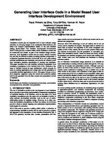
A Dialog-oriented User Interface Generation Mechanism Jeongwon Baeg Dept. of Electrical Engineering Waseda University 3-4-1 Okubo, Shinjuku-ku, Tokyo 169, Japan baeg @fuka.info.waseda.ac.j p
Yoshiaki Fukazawa Dept.of Information & Computer Science Waseda University 3-4-1 Okubo, Shinjuku-ku, Tokyo 169, Japan
[email protected]
Abstract
in case of interface builders, little or no support is provided to select appropriate interaction items and to enumerate interaction items according to dialog sequence for a specific application [5] UIMSs based on the traditional Seeheim structure, on the other hand, because they stress dialog description technique (such as dialog control models [6]) rather than implementation technique, lack adequate implementation support. There are UIMSs with implementation support [5] [8], however, even they suggested complex mechanism for determining presentation style. To solve described problems in the above, in this paper we describe an approach to easily and quickly build a GUI application by automatic interface generation from simple dialog description and by interactive customization using an interface builder according to desired presentation style. Some features of our approach follow:
Nowadays, f o r GUI application development, a number of interface builders make possible for the user to create user interfaces easily and UIMSs help to speci f y and design user interfaces. However, interface builders lack support of selecting appropriate interaction items f o r a specific application and UIMSs have little support of low-cost implementation technique because they have concentmted on the description technique. To solve these problems, in this paper we describe an approach to support both design and implementation activities on GUI application development by generating a default interface from described dialog and by customizing the generated interface interactively using an interface builder. It enables to decrease development costs by supporting GUI development from the early stage and by excluding the necessity of specifying and preparing design rules f o r presentation style.
~
By supporting dialog description and generating a default interface from it, our approach supports GUI application software throughout the development process, from the specification phase to the run-time phase.
1. Introduction For GUI(Graphica1 User Interface) application development, a number of researches on user interface builders [l] [2] and UIMSs(user interface management system) [3] [4] have been advanced in the last years. Compared to traditional programming with GUI toolkits, interface builders make possible for the user to create user interfaces easily and quickly by dragging onto the work surface and arranging with direct manipulation. Also, many UIMSs have been suggested to help to specify and design user interfaces effectively. However, despite many available tools, the development of GUI applications is still a time-consuming activity because there are few effective methods to support their whole development process. For example,
By generating a default interface and by customizing it interactively with an interface builder, our approach supports rapid prototyp-
ing and decreases development costs It enables developers to construct GUI applications without having to specify and prepare design rules for presentation style. 0
3 10 0-8186-7638-8/96 $05.00 0 1996 IEEE
Unlike other approaches, ours requires neither a particular dialog description model nor a particular interface builders.
2. Related Work There are several studies that discuss automatic user interface generation from the dialog description [51 PI [91 [io]. In GENIUS [5] and ITS [8], constraints and design rules are used to achieve their desired presentation style. However, the rules concerning formats and locations of interaction items are themselves difficult to write, and it is also difficult to completely meet any desired configuration by adjusting those rules. Our approach, however, avoid those difficulties by generating a default interface and allowing the interface designer to realize his desired configuration through direct manipulation using an interface builder generated. Some other studies tried to generate interaction items from application program code [9] or from application specifications [lo]. In case of [lo], they have no dialog specification stage, they lack the support to review how t o control the dynamic behavior of visual context. Our approach solves this problem by adopting interface generation technique based on dialog description t o be able to control visual context. [9] takes similar approach with us on the aspect that interactive customizing of the generated interfaces for the desired presentation style without style rules, however, that approach needs specific libraries and complex mechanisms for customization as well as efforts to learn specific libraries at development process. Compared with that, we requires no particular libraries and learning efforts. In summary, then, in comparison with existing systems of automatic user interface generation, our approach provides a simpler description technique and easier construction of GUI-based software via methods that require neither large time investments nor GUI programming experience.
3. Development Process with Our Syst em
I
Presentation
i......"..!-." i
'-
Dialogue Control
.-
Application interface
Our system architecture is based on the most widely known Seeheim model [4]as shown Figure 1. According to this model, GUI application system consists of three layers. The primary component is the dialog control which is receives inputs, determines what should be done about them, and requests services from the application. The functional code is accessed via some application interface, which is also called the semantic interface. The presentation consisted of all those issues that control the visual appearance and physical device selection of the actual interface. We tried to automatically generate the presentation, dialog manager, the partial functional core from the dialog control according t o this data display facet of the model. Our main idea does not need any particular dialog description model [ll] [12] [13] and interface builder tool compared to [5] [8] [lo] [9]. However, at least our approach requires to build a suitable system according to the chosen dialog model and interface builder. For our approach, we selected state diagrams as a dialog description model because the concept of moving from state to state upon given inputs is not difficult to teach to non-programmers. Also, we selected XF tool as an interface builder [14]. XF tool is a user interface builder based upon Tcl and T k , which is used to arrange and configure a generated default GUI. We assumed separate tasks are undertaken by dialog designers, graphics designers, and application programmers during the development process. The development process of a GUI application by our approach consists of the following stages based on our system structure as shown in Figure 2. 1. The dialog designer specifies when logical inputs are acceptable, what semantic actions to invoke. and how to control the dynamic behavior of visual context (including, for example, how the interface shifts between windows in response to user needs.) To offer support to designers at this stage, we built a state diagram editor so that the dialog designer can describe the state transition model in both graphical and textual form.
2 Our code generator produces default interaction items such as buttons, scrolling lists, pull-down menus, new windows, a dialog manager program, which defines the dialog interaction sequence, and an application skeleton. (All are generated from described state transition diagrams.) We call the interface containing these default items
:core
A-
' I i ....... _............ ...... ............. .i "
"
I
the pre-customized GUI. Our dialog manager
Figure 1. Seeheim model for UlMS architecture
program includes a dialog control part, and our application skeleton includes a header part, as
311
well as some condition clauses in a procedure to be invoked by user’s inputs. All generated code is written in Tcl/Tk script. The graphics designer can modify and refine the generated pre-customized GUI interactively with an interface builder such as XF tool. The output of our code generator is a Tcl/Tk script, therefore, the code can be loaded and modified directly on the X F tool.
. . .” . 1 ”... .. ,..,
The application programmer writes the internal details of the procedure to be invoked by the user’s input action and completes a GUI application system by adding them to application skeleton generated in the second step.
Dialog Designer
2-
.....
Figure 3. An example of a state transition diagram
current states, user’s inputs, execution condition, and actions to be invoked. The Figure 3 is a part of our state transition model describing dialog of a state transition diagram editor which we built. As shown in Figure 3, circles represent states, and texts on arcs represent the designation of interaction items, the user’s events, execution condition, and actions to be invoked. One example in Figure 3 illustrates partially dialog description of our state transition dialog editor. This figure shows that one menu button and five buttons are displayed at one window and when an user event is occurred on the menu button “Button Press” and the user selects “New” in the menu items , “Createsheet” action will be performed. Some notations and rules are defined to describe the dialog with the state transition diagram. In the following section, each part of Figure 3 will be described. Present our system should be improved on the aspect of dialog description definition because the current system was made only for validation of effectiveness of our met hod.
State Transition Diagram Editor
Code Generator
Graphics Designer
XF tool
Text Editor
t
2
Application programmer
Figure 2. System structure
4.1. States The states of an application are changed into the next states based on the current state and the current user’s event. In our system, the state starts from state “1” and finishes to state “E’’ of one thread of a dialog. For example, an arc drawn from 1 in a circle to 2 in a circle means moving from one state to next state sequentially. The numbers represent sequence of change of its states in an application. Every state can be divided into several sub-dialog description. Each sub-dialog can be defined depending
4. State Transition Diagram for Dialog
Control The state transition model can represent the meaning of the user’s inputs based on the current state of the dialog. The meaning of a given input is determined by where it occurs in the sequence of inputs. To represent dialog control, our state transition diagram consists of
3 12
[Blbuttonl] : Create a button widget, “buttonl” in a main nindow. Blbuttonl : Create a button nidaet. “buttonl” in a child window. [mblfile] : Create a menu button widget, - “file” in a main window. menuINew ; Create a menu, “New” in the menu button “
4.2.2. Description for Events
7
We expressed the notations of events similarly to the Tcl/Tk script. For example, “ShZft-B~tt~nl~’ represents the event the first button of the mouse is pressed while shift key is pressed as the Tcl/Tk script. The following explanation shows the detail event type to be specified according t o our description notations partially. There are three event types based on the user’s input action in the interaction aspects, and some events can be represents by combination of these events.
Figure 4. Examples of description for interaction items
on every state. The overall structure of the dialog can be built by assembling all sub-dialog descriptions.
4.2. Transitions
0
Arcs are drawn to represent transitions from one state to other state. Texts written on arcs consist of description for interaction items to be occurred the user’s event, the user’s inputs, procedures to be invoked, and description for condition.
Event in windows : the focus moved into a window.
When the logical event is received at the current state, the action will be triggered and after the action is executed the state transfers the next state. In our state diagram, for example, “:PopFaleLisf’ represents “PopFileList” procedure to be called as an action by the user’s input event. The actions are surrounded by “{” and “}”. The internal details of a given action to be triggered by the events are not described. The name of the action is only noted. However, in case that the window is pop-uped by the event, i.e., in case that the interaction items are required to newly generate by the user’s inDut. we determined to describe some kind of those actions differently from the above procedure because some events occurred from the child windows. The actions of those cases are represented with “0’and “)”. For example, (Can Iwindowl) represent new canvas named “ windowl” will be generated when a user’s action occurs. This kind of description can be simply written by a menu-driven system shown as an inner panel of Figure 5 .
In our system, 15 kinds of interaction items can be described based on the graphics library of XF tool, which is similar to the standard graphics components of other interface builders. The following shows a part of description for interaction items defined by our system.
“B” represents a button widget, which is associthat invokes an action ated with Tcl in the application.
A
“menu” represents a pop-up menu widget which
is posted in response to a keystroke or other event in the application. 0
expresses that
4.2.3. Description for Procedures
4.2.1. Description for Interaction Items
0
Mouse event : is an event that the first button of a mouse is pressed once. Key event : means that the input of key “a”is received.
“Top” represents the widget of toplevel, which is a building block for widget layout and it is created as a new main window. This definition is used to create a new window to control the dialog of a visual context. Interaction items t o be generated on the main window are used with “[,, and “I” and interaction items in the child window are written without ‘P and “y.
I
4.2.4. Description for Condition Some procedures of an application will be acted on under some condition of the current state of an application. For example, under the situation which other event is received or some conditions t o perform an action are satisfied, when the button is pressed, a procedure may be invoked. For that situation, we determined some notation to describe condition in a state
‘‘I” is the split representation to discriminate the name and the kind of widgets. Some examples in the Figure 4 are described according to the above notations.
313
transition diagram because a state transitim diagram does not have enough description power to represent some conditions before one state transfers the next state under certain input. As our definition, a condition is described between “(” and “)” , the name of interaction items to be acted on is described at right hand side of “(” “)”. Some examples described with several conditions are shown as follows. (destroy)top2
When the toplevel window “top2” is only destroyed, the designated procedure from a certain widget will be performed.
Figure 5. Menu-driven dialog description
(f ocusIn) widget I When certain widget is focused in itself, the designated procedure will be performed.
2. Condition information The second entry box in a window of the right side of Figure 5 is prepared for defining some conditions under which a user’s event is available.
4.3. State Transition Diagram Editor We built a state transition diagram editor which has several facilities. They will be explained at the following sections in more detail.
3. Bind information A sequence of events from the X window system such as key press, button press are defined in the third entry box in a window of the right side of Figure 5. Also, procedure names to be performed after binding defined events are written in it.
4.3.1. Tracing the State Transition The dialog designer can trace states in an application, detect the wrong definition of a dialog and rebuild the diagrams repetitively. Graphically written state transition diagram is recorded textually in a certain file. The designer can select necessary transitions and trace application states.
4. Description for interaction items to be pop-uped When a child window is created by a user’s event, interaction items to be placed on a child window are defined in the forth entry box by selecting appropriate menu items among menu buttons in the right-hand window of Figure 5.
4.3.2. Menu-driven dialog description
5. State transition information A user interface as shown Figure 5 was built to support easy description, which allows the dialog designer to edit with both textual way and a menu-driven way. In the case of menu-driven editing, by selecting just necessary menus, the dialog designer can describe the dialog simply and easily without knowledge on the detail description notations and rules. Each interface for both textual editing and menudriven editing is explained as follows.
A sequence of start state and next state to be transferred is defined in the last entry box in a window of the right side of Figure 5. The described sequence corresponds to each state which is written in a canvas widget already. 4.3.3. Showing code generated from the dialog description The application programmer can observe and refer both the dialog manager and the application skeleton code generated from the dialog description given by the dialog designer. The programmer can complete the whole application system by adding functional core for a specific application to generated code while editing
1. Description for interaction items The first entry box in a window of the right side of Figure 5 is prepared so that the dialog desimer can define interaction items to be generated according to the rules as explained in section 4.2.
3 14
and executing code with a facility which our state transition diagram editor provides. This function enables rapid prototyping, which is one stage of a successful application development process.
0
Simple manipulation such as dragging can be done using interface builders.
These process can be done not by GUI expert programmers but by end-users or even graphics designers with esthetic sense. We can address partition of role as our approach is an important process from the point of view of the software development.
5.1. Generation of GUI The dialog designer discriminates interaction items will be generated on the main window or child windows and describes according to the rules as described at section 4. First of all, default items to be placed on the main window will be generated based on the state transition description. Next, if the dialog is designated so that subsequent dialog can move on the child window according to user’s events and when any user’s event occurs on an interaction item in the main window, a child window will be pop-up and some default interaction items are generated on its child window.
Figure 6. Generated code
4.3.4.
Executing the generated code
The developers including the dialog designer, graphics designer, and the application programmer can see and review both the graphics components on the screen. After reviewing the screen design, state transition diagram can be rewritten and generated code can be executed repeatedly. This facility makes it possible to build rapid prototypes and enables the end-user’s involvement from the beginning of the development process.
5. Generation and Customization Generally the definition of where to place interaction items in the several windows to be pop-uped is described in dialog control. However, specific layout such as the size and arrangement is not designated. Best look and feel of the interface cannot be obtained from the design on the paper. In our system, a default interface to be called precustomized GUI is generated from the dialog description. The generated GUI covers necessary and satisfactory interaction items, however, specific layout are not applied yet. Specific layout will be accessed by using one of interface builders in regard to pre-customized GUI. The result GUI to be completed by this process is called post-customized GUI. Customization will be performed while focusing on the following aspects. 0
Figure 7. Generated GUI
The Figure 7 represents one example of precustomized GUI from the dialog description of Figure 3. The left side of Figure 7 is the window generated from dialog description at first, and in this window when the “script” button is pressed, the right side window is pop-uped as shown Figure 7.
5.2. Customization of a generated GUI From the generated interaction items, the graphics designer can customize the size and arrangement of them while reviewing the look and feel of the interface from the end user’s perspective interactively using
Layout on the size and arrangement can be applied regardless of the number and kinds of interaction items.
315
39 (numbers)
panel
9 scrollbar 9
I
1
I
button 13 list box
I
8
1
I
51
32
I (numbers) I
I
(pieces)
menubutton 2 label 8
210 (minutes)
menu
canvas 1 entry text 1 2 1 1
8
6. Experience Figure 8. Post-customized GUI
+
Our system was implemented under Sun OS 4.1.3 T k version 3.6 on
+
XF version 2.3 Tcl version 7.3 SUN SPARCstation 20.
The ~i~~~~ 8 shows 2 menu buttons and 7 buttons as the result obtained by modifying and refining precustomized GUI generated as shown in the Figure 7. The text strings on the 7 buttons could be replaced by bitmap images for the look and feel of the graphits designer. The XF tool supports to simply insert other images made by the graphics designer to generated interaction items such as buttons by designating the name of image files.
+
At first, we tried to describe dialog of our state transition diagram editor which we built. Table 1 shows the results applied to dialog of our editor. The number of all generated items was 51 pieces, It took about 190 minutes to describe dialog and 20 minutes to modify generated items according to desired configuration using the XF tool. It takes a time for a dialog designer to describe the dialog, however, once interaction items are generated, it can take very short time until completion of view parts of a GUI application. In other words, the application programmer can be freed from any burden of GUI programming.
The Figure 9 shows another would-be desired configuration different from Presentation style of Figure 8 by another customization way for Figure 7.
Table 2 shows the number and kinds of interaction items generated from the dialog description.
A Tcl/Tk script consists of one or more commands and each command consists of one or more words 1151. Therefore, we evaluated the scale of the whole system by counting words of generated code with Tcl/Tk script. Table 3 shows the scale of generated code, generated code was about 17 % of total code, which can help the application programmer to reduce debugging time for the control flow of interaction and the view part in a whole system, in comparison t a the case that he should write all control flow without dialog description and GUI programming as traditional works.
Figure 9. Another post-customized GUI
3 16
[7] Olsen, D. R., Buxton, W., Ehrich, R., Kasik, D. , J . Fihyne, and J.Sibert, “A Context for User Interface Management ,” IEEE Computer Graphics and Applications, Vol. 4, No. 12, pp. 33-42, 1984.
Table 3. Scale of nenerated code.
1
(words \
6257
generated code(words)
1 procedure I 1 skeleton 1 I
253
I
dialog manager 97
I interaction
I
items
[8] Wiecha, C., Bennett, W., and Boises, S. Gould, J . and Greene, S., “ITS: A Tool for Rapidly Developing Interactive Applications,” A CM Transactions on Information Systems, Vol. 8, No. 3, pp. 204-236, 1990.
I 689
7. Conclusion We presented a new idea to make construction of a GUI application easy and quick by integrating a dialog controller and an interface builder. In our prototype system, automatic interface generation from various types of dialog such as multi-thread and concurrent dialog is limited because we selected state transition model. This kind of limitation cannot be an critical point of our method. In order to evaluate the portability of our method, we are currently working with Petri nets instead of the state transition diagram. Our method can generate and customize only standard interface independent of specific applications. In the futuer, we will try to handle application dependent interfaces. We are also considering another GUI application development strategy such as construction of GUI systems under the distributed environment for more effective development process.
[9] Kitamura, M. and Sugimoto, A., “GhostHouse : A Class Library for Generating Customizable Graphical User Interfaces,” In Journal of IPSJ ’95, pp. 944957, IPSJ, 1995. (in Japanese)
[lo] de. Barr, D. et.al, “Coupling Application Design and User Interface Design,” In Proc. CHI’92, pp. 259-266, ACM, 1992.
[ll] Wellner, P.D., “Statemaster, A UIMS based on Statecharts for Prototyping and Target Implementation,” In Proc. CHI’89, pp. 177-182, ACM, 1989. [12] Baeg, J., Hirahara A., Fukazawa, Y., “An Adaptive User Navigation Mechanism and its Evaluation,” In Proc. APSEC’94, pp. 29-37, 1994. [13] Working Party X/3, “Draft Recommendation Z.120-Message Sequence Chart(MSC),” CCITT, Mar 1992.
References
[141 Delmas, S., “XF(xf-2.3~11),” ftp.cs.tu- berlin.de.
Sun Microsystems, Inc., Open Windows Developer’s Guide 1.1, Reference Manual, Part No. 8005380-10, Revision A, 1990.
[15] Welch, B., Practical Programming in Tcl and Tk, Prentice Hall PTR, 1995.
Armstrong J.C J r , “Six GUI Builders Face Off,” Sun World, December, 1992. Olsen, D. R. , “User Interface Management Systems: Models and Algorithms,” Morgan Kaufmann Publishers, Inc., 1992. Szczur, M.R. and Sheppard, S.B. : TAE Plus: Transportable Applications Environment Plus: A User Interface Development Environment, A CM Trans. Info. Syst., Vol. 11, No. 1, pp. 76-101, 1993. Janssen, C., Weisbecker, A., and Ziegler, J., “Generating User Interface from Data Models and Dialog Net Specification,’’ In Proc. INTERCHI’93, pp. 418-423, ACM, 1993. Bass, L. and Coutaz, J., Developing Software for the User Interface, Addison-Wesley Publishing Company, 1992.
317