New Materials and Innovative Technologies to Improve the Efficiency of Three-phase Induction Motors. A Case Study E. Chiricozzi, F. Parasiliti, M. Villani Department of Electrical Engineering, University of L'Aquila I-67100 Monteluco di Roio, L'Aquila, Italy e-mail:
[email protected];
[email protected];
[email protected]
Abstract - The paper presents the results of a research project whose aim was the investigation of the efficiency improvement of industrial three-phase induction motors when high quality electrical steel is adopted in combination with die cast copper rotor cage, in order to define the design strategies; to verify the actual efficiency improvements; to verify the arrangement of the motors respect to the European Classification Scheme (EC-CEMEP). The results are related to the cheapest design strategies when “premium steel” and copper rotor cage are used instead of standard steel and aluminum cage, with standard and higher stack length. The considered motor sizes are 3 and 7.5 kW, 4 pole, 50 Hz, 400 V, TEFC.
I. INTRODUCTION The European Scheme to designate energy efficiency classes for low voltage AC motors has been in operation since 1999. It is based on a voluntary agreement between the European Commission and CEMEP, the European Committee of Manufacturers of Electrical Machines and Power Electronics [1]. This Scheme classifies induction motors into three efficiency bands, from Eff3 (lowest) to Eff1 (highest). This agreement should stimulate the Manufacturers in the development of new ranges of high efficiency motors that requires an accurate motor design, the adoption of new materials (e.g. premium steel) and innovative technologies (e.g. copper rotor cage die-casting). The magnetic material plays a significant role in the improvement of the motor performance [2]. Respect to this goal, its main features are the magnetic permeability and the specific losses. Moreover, the choice of a “suitable” electrical steel depends on several aspects such as cost, workability, annealing (when needed), “business tradition” and storehouse demands. Developing new ranges of high efficiency motors, the choice of the magnetic material is today an “open problem”. On the other hand, it is well known that incorporation of copper for the rotor bars and end rings in place of aluminum would result in attractive improvements in motor energy efficiency [3], [4]. Up today, only small numbers of very large motors utilize copper in the rotors by mechanical fabrication. Such fabrication involves intensive hand labour and therefore is expensive [5], [6]. Die casting is widely recognized as a low cost rotor cage manufacturing process. For these reason, die-casting has become the fabrication method of choice and aluminum the conductor of choice in all but the largest frame motors. Copper die-cast rotor construction does not differ significantly from the aluminum one and, in essence, the manufacturing details are identical. The additional manufacturing challenges are increased temperatures and pressures required to die-cast copper. The primary reason copper die-cast rotors are not
commonplace yet is because it requires specialized equipment (investment) and know how in this field. Aim of the proposed paper is to investigate the improvement of the efficiency of industrial three-phase induction motors when high quality electrical steel is adopted in combination with die cast copper rotor cage. This activity falls in a research program partially supported by the MIUR (Italian Ministry for Education, University and Research) and concerning the study of motors and drives energy efficiency increase in industrial and civil applications. The project has been developed in co-operation with three important European companies: − ThyssenKrupp ES Acciai Speciali Terni, Italy, European leader in the production of electrical steels for electromechanical applications; Acciai Speciali Terni has provided several electrical steels that have been used in the new prototypes; − LAFERT S.p.A., one of the most important Italian manufacturer of induction motors; LAFERT has provided the stator and rotor cores and stator windings and has assembled the prototypes with copper rotor cages; − FAVI (Fonderie et Atelier du Vlmeu), French company specialized in copper alloy pressure die-casting; FAVI has co-operated manufacturing a line of hightemperature moulds and several copper rotor cages. The aim of the project was the analysis and the construction of several prototypes of induction motors by using the above mentioned innovative technological solutions, in order: − to define the design strategies; − to verify the actual efficiency improvements; − to verify the arrangement of the motors respect to the European Classification Scheme (EC-CEMEP). The analysis concerns with industrial low voltage three-phase induction motors, 4 pole, 50 Hz, 400 V, TEFC, in the 0.75÷22 kW power range. In order to obtain high efficiency motors making use of die-cast copper rotor cage and premium steel, the following design strategies have been investigated: 1. substituting copper cage for aluminum cage and standard electrical steel, without changing any motor dimension; 2. substituting copper cage for aluminum cage and high performance electrical steel, without changing any motor dimension; 3. design optimization of copper cage motor by changing the stator winding and the stack length only; 4. design optimization of copper cage motor by changing the stator winding, the stack length and the stator and rotor figures. The paper presents the results related to the cheapest design
strategies 1), 2) and 3) when “premium steel” and copper rotor cage are used instead of standard steel and aluminum cage, with standard and higher stack length. The considered motor sizes are 3 and 7.5 kW.
II.
RESEARCH PROJECT DEVELOPMENT
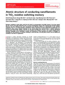
The minimum nominal efficiencies for these motors according with the EC-CEMEP standard are show in Table I. To evaluate the efficiency improvements, two standard motors have been chosen as “reference motor”: they are commercial motors with aluminum rotor cage and standard electrical steel belonging to the low efficiency class Eff3 (Fig. 1). Taking into account the tolerance on efficiency measurements standards, the 3 kW motor could be classified in the Eff2 class. Table I EC-CEMEP Minimum Efficiency Standard for 4-pole Motors Eff2 82.6 87.0
Eff1 87.4 90.1
2500 µp (1.5 T) 2000
95.0
8050
5350H 5350
1000 3150
500
2
3
5
4
6
W/kg (1.5 T)
Figure 2. Permeability and loss at 1.5 T of the considered steels
Eff 1
η
8050H
1500
B (T)
kW 3 7.5
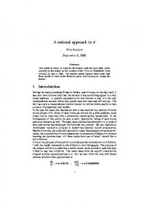
low specific losses (Fig. 3) with high permeability (better than 8050 under 1.2 T, a little bit worse over, Fig. 4). On the base of these preliminary analyses and the material hardness, the high permeability steel 5350H has been chosen as “premium steel”.
2
1.8
1.6
Eff 2
1.4
90.0
1.2
Eff 3
1
5350H 0.8
85.0
84.2
0.6
8050 0.4
82.0 80.0
0.2
0
1
Loss (W/kg)
10
10
Figure 3. Specific losses curves of 8050 and 5350H steels
3.0
7.5
15.0
kW
B (T)
75.0
2
Figure 1. Standard motors placements in the EC-CEMEP Classification Scheme.
1.8
A. Choice of the electrical steel
1.4
Concerning the choice of the electrical steel, we compared the standard one used in the reference motors, labeled 8050, with several alternative electrical steels classified as: - low loss electrical steels: 5350 and 3150; - high permeability electrical steels: 8050H, 5350H. Their main characteristics are summarized in Fig. 2. The influence of the considered electrical steels and copper rotor cage on motor performance have been evaluated by simulations. The results have been compared with commercial motor ones in order to evaluate the achievable improvement due to the use of “premium steels” and copper cage only without affecting the design of standard motors. Frequently better magnetic materials from the losses point of view have worse permeability (in Fig. 2 see electrical steels 3150 and 5350 in comparison with 8050). Electrical steel 5350H represents the most suitable choice because combines
1.6
1.2
1
5350H 8050
0.8
0.6
0.4
2
10
3
10
H (A/m)
4
10
Figure 4. B-H curves of 8050 and 5350H steels.
B. Motor Prototypes The motor prototypes have been realized according to the following combinations, for each power size: a) aluminum cage and standard steel 8050 (commercial
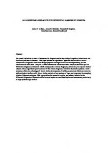
“reference motor”); the corresponding prototypes are labeled “Al 8050”; b) copper cage and standard steel 8050; the prototypes are labeled “Cu 8050”; c) copper cage and premium steel 5350H; the prototypes are labeled “Cu 5350H”; d) copper cage, standard steel 8050 and higher stack length (HSL); the new stack length is consistent with the standard housing; the prototypes are labeled “HSL Cu 8050”; e) copper cage, premium steel 5350H and higher stack length; the new stack length is the same of case d); the prototypes are labeled “HSL Cu 5350H”. Comparison between motors a) and b) allow to evaluate the improvements achievable with copper rotors only. The comparative tests have been carried out by adopting the same stator core and winding: in this way any difference in performance due to the production process has been avoided. Motors c) results will show the effects of the premium steel (in comparison with motors b)) and the improvements respect to the standard motor (in comparison with motors a)). Motors d) and e) results will show the improvements suitable with a low cost re-design strategy, when costly new lamination punch and new stator housing tools should be avoided. Table II presents the main dimensions and weights of the prototypes (reference motors and new prototypes) while Fig. 5 and Fig. 6 show views of the copper rotors. Table II Prototypes main dimensions and weights 3 kW
7.5 kW
Stack length (mm) Out. stator diam. (mm) In. stator diam. (mm) St. winding weight (kg)
130 152 90 2.45
160 200 127 5.40
Rotor cage weight (kg) Al Cu
0.74 2.43
1.45 4.77
Gross iron
22.4
47.8
(kg)
3 kW
7.5 kW
HSL
HSL
155 152 90 2.82 (+15%)
180 200 127 5.9 (+7%)
5.20 2.73 (+12%) (+9%) 26.8 53.8 (+20%) (+12%)
Figure 6. View of standard and higher length copper rotors, 3 kW motor.
III. RESULTS A.
Standard test method
In order to evaluate the copper rotor and premium steel effects on each loss category and to obtain an accurate efficiency measurement, a loss segregation method is required. IEEE 112-B and CSA C390-98 methods are true input vs output power efficiency tests that segregate losses into five categories: Iron Losses, Stator Resistance, Rotor Resistance, Friction and Windage (F&W) and Stray Load Losses (SLL). The first four are measured directly and the remainder is the “stray load” category. The experimental results presented in the paper refer to the Standard CSA C390-98.
B.
Motors test results
Table III shows the efficiency and loss segregation test results of the 3 kW motors; the comparison between standard length new prototypes (Cu 8050 and Cu 5350H) and commercial motor Al 8050 is presented. Table III CSA C390-98 Efficiency and Loss Segregation Test Results. 3 kW standard stack length motors. 3 kW η % Σlosses (W) Stator wind. Rotor cage Iron SLL F&W
Figure 5. View of standard length copper rotors, 3 and 7.5 kW motors.
Al 8050
Cu 8050
Cu 5350H
82.0 655 351 153 117 13 21
84.1 (+2.1) 563 (-14%) 327 83 (-46%) 124 13 16
84.5(+2.5) 545 (-17%) 337 83(-46%) 94(-20%) 8 23
The substitution of copper as rotor material has allowed to move the 3 kW motor in the Eff2 class, while the use of the 5350 H electrical steel does not give rise any further efficiency class movement. Concerning the other motors performance (Table IV), with copper rotor and premium steel the stator winding temperature rise ∆TSW is reduced by 16°C and that is a very important feature because temperature rise is significant in the life expectancy of the motor and lower temperatures mean that
smaller cooling fans can be used: this has a significant effect in reducing the friction and windage losses. Power factor is constant while slip is significantly lower for both copper motors: copper motor generates a higher torque at same slip than the aluminum motor one. This implies a very good response on variable frequency drives, but potential problems on variable torque loads like fans and pumps. Copper motors exhibit substantially constant breakdown torque TB (+ 8%) but a significant drop in the locked rotor torque TL (- 18%), due the rotor laminations designed for aluminum. Table IV 3 kW standard stack length motors performance 3 kW I (A) ∆TSW (°C) Power Factor Slip % TB (Nm) TL (Nm)
Al 8050
Cu 8050
Cu 5350H
6.86 87 0.76 4.83 58 54.4
6.70 83 (-4) 0.76 2.69 (↓) 63 46.9 (↓)
6.73 71 (-16) 0.75 2.7 (↓) 62 42.8 (↓)
Concerning temperature, slip and locked rotor torque, tests of 7.5 kW motors (Table V and Table VI) confirm what found for the smaller motors. The efficiency improvements are 3.2 and 3.9 points respectively. Nevertheless, the motors do not move in the Eff1 class, stopping in Eff2. Table V CSA C390-98 Efficiency and Loss Segregation Test Results. 7.5 kW standard stack length motors. 7.5 kW
Al 8050
Cu 8050
Cu 5350H
84.2
87.4 (+3.2)
88.1 (+3.9)
Σlosses (W)
1401
1077 (-23%)
1035 (-26%)
Stator wind. Rotor cage Iron SLL F&W
466 284 361 237 53
456 141 (-50%) 349 92 39
423 138 (-50%) 338 88 48
η
%
Tables VII and VIII show test results of the 3 kW higher stack length prototypes. With standard steel 8050 the measured efficiencies are 2 points higher respect to the corresponding copper rotor motor with standard stack length and 4 points higher respect to the commercial aluminum rotor motor (Table III). With premium steel 5350H the measured efficiencies are 2 points higher respect to the corresponding copper rotor motor with standard stack length and 4.5 points higher respect to the commercial aluminum rotor motor. The most significant loss reduction is in the stator winding. Comparisons between Table IV and Table VIII show relevant temperature reductions, the same locked rotor torque and the increasing of the breakdown torque respect to the standard motor AL 8050. The new motors remain in the Eff2 class, but could be labeled Eff1 motors if the tolerance is taken into account. Table VII CSA C390-98 Efficiency and Loss Segregation Test Results. 3 kW Higher Stack Length motors. 3 kW
HSL Cu 8050
HSL Cu 5350H
86.0 486 265 73 113 15 20
86.5 465 265 77 99 9 15
η % Σlosses (W) Stator wind. Rotor cage Iron SLL F&W
Table VIII 3 kW Higher Stack Length motors performance 3 kW I (A) ∆TSW (°C) Power Factor Slip % TB (Nm) TL (Nm)
HSL Cu 8050
HSL Cu 5350H
6.76 58 0.74 2.36 69 53
6.79 57 0.73 2.49 69 55
Table VI 7.5 kW standard stack length motors performance 7.5 kW I (A) ∆TSW (°C) Power Factor Slip % TB (Nm) TL (Nm)
Al 8050
Cu 8050
Cu 5350H
15.0 104 0.86 3.44 165
15.2 86 (-18) 0.81 1.82 (↓) 155 110 (↓)
14.8 80 (-24) 0.82 1.79 (↓) 108 (↓)
Further improvement on motor performance can be achieved if copper rotor and premium steel adoptions are combined with higher stack length and new stator winding. The new motors have been designed by a suitable software that combines a motor simulation model with an optimization algorithm [7]. The new stack lengths are consistent with the standard housings. Two higher stack length (HSL) copper rotor prototypes have been realized for the 3 kW size, with 8050 and 5350H electrical steels; only one for the 7.5 kW size, with 5350H.
Table IX shows test results of the 7.5 kW higher stack length prototype. Comparison with Tables V and VI show efficiency increasing of 5 and 1 points respect to aluminum and copper rotor standard stack length motors; further decreasing on temperature and slip can be pointed out. However, it is still in Eff2 efficiency class. Table IX CSA C390-98 Efficiency and Loss Segregation Test Results and motors performance. 7.5 kW Higher Stack Length motor. 7.5 kW η % Σlosses (W) Stator wind. Rotor cage Iron SLL F&W.
89.0 919 334 113 315 110 47
HSL Cu 5350H I (A) ∆TSW (°C) Power Factor Slip % TB (Nm) TL (Nm)
14.7 59 0.82 1.46 -
C.
Summary of the results and comparison with literature data
Table X summarises the overall motor efficiencies experimentally observed in motors fitted with copper rotors where comparisons with aluminum are reported in literature including the data of this study. The range 3÷18.8 kW, 4 poles motors is covered. Table X Overall motor efficiencies via copper rotors. Data from this study and the literature. kW
Hz
Efficiency Al
Reference
CU
86.4 (*) 83.2 60 3 84.1 (*) 82.0 50 3 84.5 (x) 50 3 86.0 (+) 50 3 86.5 (o) 50 3 87.4 (*) 84.2 50 7.5 88.1 (x) 50 7.5 89.0 (o) 50 7.5 90.7 (*) 89.5 60 11.2 91.0 (*) 90.1 50 15 92.5 (*) 90.9 60 18.8 (*) standard design, standard steel (x) standard design, premium steel (+) higher stack length, standard steel (o) higher stack length, premium steel
4 This study This study This study This study This study This study This study 4 8 4
improvements vary from 2.1 points for the 3 kW to 3.2 points for the 7.5 kW. The use of 5350H electrical steel (premium steel) improves efficiencies of 0.4 and 0.7 points from smaller to larger motors. However, premium steel and copper rotor do not give rise any further movement (from Eff2). The third series of prototypes have higher stack lengths, but consistent with standard housing, and optimised new stator windings. In case of 3 kW size, the new motors remain in the Eff2 class, but could be labeled Eff1 motors if the tolerance is taken into account. In spite of about 5 points gained respect to the standard motor efficiency, the higher stack length 7.5 kW motor is still in the Eff2 class. This result is strongly conditioned by the original standard design (stator and rotor figures are not changed), very poor from efficiency point of view. In any case, better results could be achieved if the adoption of new materials and innovative technologies are associated with an accurate motor design that allows to exploit the advantages of copper cage and premium steel.
REFERENCES [1]
[2]
IV. CONCLUSIONS [3]
The paper presented test results concerning several prototypes of induction motors with die-cast copper rotor cages and premium electrical steel with the aim to verify the actual efficiency improvements and the arrangement of the motors respect to the European Classification Scheme EC-CEMEP. Two standard motors (3 and 7.5 kW) have been chosen as “reference motor”: they are commercial motor with aluminum rotor cage and standard electrical steel belonging to the low efficiency class Eff3. The efficiency of the 7.5 kW motor is far from the boundary of Eff2 class (2.8 points less than the lower limit) while the 3 kW motor is very close to it: in fact, taking into account the tolerance on efficiency measurements standards, the 3 kW motor could be classified in the Eff2 class. Three design strategies have been investigated: 1. substituting copper cage for aluminum cage and standard electrical steel, without changing any motor dimension; 2. substituting copper cage for aluminum cage and high performance electrical steel, without changing any motor dimension; 3. design optimization of copper cage motor by changing the stator winding and the stack length only. The substitution of copper for aluminum has allowed to move the 3 and 7.5 kW motors in the Eff2 class. The efficiency
[4]
[5]
[6]
[7]
[8]
Bertoldi P., Kuehnemund G., “The European Negotiated Agreement to Improve Motor Efficiency”, “Energy Efficiency Improvements in Electric Motors and Drives”, Editors: P. Bertoldi, A. de Almeida, H. Falkner, Springer, 2000, pp. 369375, ISBN: 3-540-67489-6. Parasiliti F., Villani M., “Technical and economical evaluation of electrical steels for high efficiency motors”, Transworld Research Network, Recent Res. Devel. Magnetics, n. 2, 2001, pp. 47-54, ISBN: 81-7895-001-4. Parasiliti F., Villani M., “Design of high efficiency induction motors with die-casting copper rotors”, Energy Efficiency in Motor Driven Systems, Editors: F. Parasiliti, P. Bertoldi, Springer, 2003, pp. 144-151, ISBN 3-540-00666-4. Brush E.F., Cowie J.G., Peters D.T. Van Son D.J., “Die-Cast Copper Motor Rotors: Motor Test Results, Copper Compared to Aluminum”, Energy Efficiency in Motor Driven Systems, Editors: F. Parasiliti, P. Bertoldi, Springer, 2003, pp. 136-143, ISBN 3-540-00666-4. Finley W.R., Hodowanec M.M., “Selection of Copper versus Aluminum Rotors for Induction Motors”, IEEE Transactions on Industry Applications, Vol. 37, n. 6, November/December 2001, pp. 1563 – 1573. Paris C., Walti O., “A New Technology to Make Rotors with Copper as Magnetic Conductor”, Energy Efficiency in Motor Driven Systems, Editors: F. Parasiliti, P. Bertoldi, Springer, 2003, pp. 152 – 161, ISBN 3-540-00666-4. Daidone A., Parasiliti F., Villani M., Lucidi S., “A New Method for the Design Optimization of Three-Phase Induction Motors”, IEEE Transaction on Magnetics, VOL. 34, n. 5, September 1998, pp. 2932-2935. Parasiliti F., Villani M., Paris C., Walti O., Songini G., Novello A., Rossi T., “Three-Phase Induction Motor Efficiency Improvements With Die-Cast Copper Rotor Cage And Premium Steel”, Proceedings of SPEEDAM’04 Symposium, Capri, Italy, 16-18 June 2004.