sented of a differential resonator design em- ploying a bossed structure for applications in mechanical sensors. The effects of residual strain, temperature and ...
Sensors
and Actuators
A,
2527
385
(1991) 385-393
A Differential Resonator Design using a Bossed Structure for Applications in Mechanical Sensors HARRIE A. C. TILMANS, SIEBE BOUWSTRA, DOMINICUS MESA,
7500 AE
Insfitute
for
Enschede
Marerials
Mirroelectronics, (The
Engineering,
J. IJNTEMA and MIKO ELWENSPOEK
Sensors
and
Actuators,
University
of Twente,
P.O.
Box
217,
NetherlandsJ
CARL F. KLEIN Johnson
Controls
Inc.,
Milwaukee,
WI
(U.S.A.)
Abstract Theory and experimental results are presented of a differential resonator design employing a bossed structure for applications in mechanical sensors. The effects of residual strain, temperature and mechanical load on the resonance frequency are investigated. Mismatches in the resonators are accounted for in the analysis, resulting in a predicted temperature dependence of the offset and of the sensitivity. Experimental data obtained from a macroscopic brass model, mounted on a steel bar and applied as a force sensor, are given. Compared to a design employing a single resonator, the measurements indicate a doubling in force sensitivity and a reduction of both the intrinsic temperature dependence and of the differential thermal expansion effects. The results of this research are directly applicable to micromachined structures in silicon.
Introduction Resonant sensors provide a frequency-shift output and are very attractive in the precision measurement field because of their high sensitivity, high accuracy and high stability [ 11. This paper deals with mechanical sensors utilizing resonant strain gauges for measuring a variety of loads such as pressure, force or acceleration. In a practical sensor design, the output signal responds to changes of the physical quantity to be measured but at the same time to changes of a number of unwanted 0924-4247/91/$3.50
quantities. The challenge of good sensor design is to maximize the sensitivity to the desired load and to minimize the sensitivity to others. To minimize the effects of environmental perturbations such as mass loading, humidity and corrosion, on the resonance frequency, the resonator should be housed in a stable (inert) environment, preferably a vacuum [ 2-41. The use of high-quality construction materials will result in a good long-term stability by reducing effects such as creep and stress relaxation, fatigue and aging of material properties. Temperature often remains as the major cause for error readings in the output signal. Temperature can alter the resonance frequency via two major effects. First, the material properties and dimensions, which determine the resonance frequency, are all temperature dependent, causing an intrinsic temperature dependence. Secondly, differential thermal expansion between the different construction materials causes stresses to be established, which interfere with the measurement stresses. These include the stresses caused by a thermal mismatch of the different materials used for the sensor itself, but also mounting- or packageinduced stresses caused by the differential thermal expansion between the sensor chip and the mount. Various techniques have been applied to minimize the influence of unwanted parameters. In piezoresistive devices, where temperature sensitivity is a severe problem, a Wheatstone bridge configuration and a signalconditioning IC, often including a temperature-sensitive device attached to the sensor, 0 Elsevier Sequoia/Printed
in The Netherlands
386
are used for temperature compensation [5]. Another method is to enclose the entire sensor in an accurately temperature-regulated environment, thereby minimizing the temperature changes actually seen by the sensor [6]. Recently, a ‘gas trapping compensation technique’ was reported on for a resonant pressure sensor [7]. A common compensation technique used for resonating sensors is a dual or differential design. Here, compensation is achieved by incorporating a dummy or unstressed sensor as a reference and taking the difference between the two resonance frequencies. The two sensors can also be arranged in such a way that under the influence of the measurand one frequency increases while the other decreases, e.g., in a push-pull arrangement, resulting in an increase of the sensitivity [8,9]. One step further is to use two resonators, which are integrated on the same sensor in order to provide a better matching of the resonators. This paper reports on a novel integrated differential resonator design using a bossed structure. The basic design and principle of operation are described. A centre-bossed bridge, applied as a force sensor, is analysed. The theory of the force and temperature dependence is given and is backed up with experimental data obtained from a macroscopic brass model. Mechanical coupling between the two resonators is not considered in this paper. Basic Sensor Design and Principle of Operation A cross section of the basic differential resonator design is shown in Fig. 1. It consists CAP
CAVITY
GAP
DIFFERENTIAL RESONATOR PAIR
Fig. 1. Cross-sectional view of a differential resonator design using a bossed structure for applications in mechanical sensors.
RESONATOR
1
RESONATOR
2
8RlDGEJ
Fig. 2. S-shaped deformation of the sensor structure of Fig. 1, caused by a mechanical load applied to the centre boss. The sealing cap is not shown.
of a diaphragm (circular or square) or a bridge with a centre boss. One resonator or resonant strain gauge is placed at the boundary of the frame or substrate and the other near the boundary of the boss. An external load (pressure, force or acceleration) applied to the structure causes a vertical displacement of the boss. The deformed structure will have an S-shape, see Fig. 2. Both support ends are the regions where the bending stresses are concentrated. Thanks to the S-shape, the two resonators are subjected to bending strains of opposite sign, causing the resonance frequencyf, of one resonator to decrease while at the same time the resonance frequency_& of the other increases:
(14 (lb) wherefb, andf& are the resonance frequencies of the two resonators for zero applied load and Afi and Afi are the frequency shifts of the resonators due to the mechanical load. Firstorder temperature effects and long-term drift effects cause equal shifts of fO, and f&. The shifts AJ and A1; experience (small) secondorder effects. Subtracting the frequencies of the single resonators and assuming a perfect match of the resonators results in an output signal frequency (Afi + Af2), which in first order is only a function of the applied mechanical load. If the frequency shifts of the two resonators are equal, the device sensitivity will be doubled compared to a design employing only one resonator. As depicted in Fig. 1, the two resonators are housed in a single cavity. This design, where the sealing cap is supported by the
387
frame on one end and by the boss on the other end, is attractive from a mechanical point of view [4]. Further, the ambient conditions for both resonators are now equal, providing a better common-mode rejection of environmental influences. Another relevant issue is the effect of the sensor ambient pressure, which causes a deformation of the section of the diaphragm or bridge that is protected by the cap. The deformation is sensed by the resonators and causes a shift of the resonance frequencies. But, because of the geometrical symmetry, the first-order effect of the ambient pressure will be the same for both resonators. Hence, ambient pressure fluctuations will be rejected in the difference frequency.
(3) where Q, is the built-in or residual strain as a result of the fabrication process and T is the temperature. A change Af of the resonance frequency caused by changes AE~,AT and AP in the residual strain, the temperature and the load respectively can be expressed as
Af = Mm. +
i(E>
Aq,
+[~+($)Ac,]&AT +[E+($)AQ+($)(~)AT] x;APl(I++)+{h.o.t.}
(4)
Theory
where4ntr. represents the frequency shift To study the dependence of the resonance frequency of a resonant strain gauge on the various loads, a doubly supported prismatic (wide) beam with a rectangular cross section, rigidly clamped at both ends, is taken as an example. The resonance frequency f of the beam with applied axial strain E is given by [ 81
x
1 + 0.295&(1 - v’)
due to the intrinsic temperature dependence and {h.o.t.} the less relevant second- and higher-order terms of the expansion. All partial derivatives are computed at the operating *point, defined by T = To (e.g., room temperature), P = 0 (zero applied mechanical load) and E = co, yielding a resonance frequency fo =f(W’-o), P(T,), Uo), Wo), Vo), E(E~,To, 0)). The relative intrinsic frequency shift Af,JfO, ignoring the temperature dependence of v, is to a first-order approximation given by
(2)
where E, p and v are Young’s modulus, specific mass and Poisson’s ratio of the beam material, and h and I the thickness and length of the beam. The expression given above is an approximation obtained from Rayleigh’s quotient, substituting the first mode shape for zero applied axial load as the approximate beam deflection shape. Ignoring long-term drift effects and the effects of the residual strain and of the applied mechanical load P (force, pressure or acceleration) on the material properties and dimensions, the resonance frequency of a single resonator can be expressed as
(5) where CL is the thermal expansion coefficient of the resonator material. Equation (4) can be expressed in terms of gauge factors [4] and the induced strains, yielding (ignoring (h.o.t.1)
Af A&r. -=-+[G,,AE~+(G~+AG~)AE~ h h +(G~+AGO+AGT)
A&p] l+[
1
Mm,. fo
(6)
388
where Go is the gauge factor of the resonator at the operating point, AG0 and AGT are the changes in the gauge factor due to a change in the built-in strain As, and a change in temperature AT = T - T,, respectively, and A+ and AE~are the changes in strain induced by a temperature change and a load change, respectively. The total strain E in eqn. (2) is equal to the sum of the individual strain terms, E = co+ AE~+ AE~+ A+ Equation (6) accounts for the frequency shifts due to the intrinsic temperature dependence, to a variation in the residual strain (A&,), e.g., as a result of spreads in the fabrication process, to differential thermal expansion effects (A+) and finally to the applied mechanical load (A&p). Equation (6) describes the frequency of an individual resonator. The frequency difference output (f2 -f, ) of a differential design employing two resonators with the same dimensions, material properties and operating point, and loaded in such a way that the thermal strains are equal, A.E~= A+, = AE~, and the load-induced strains are also equal, but of opposite sign, AE~ = -A+, = AE~, can be obtained from eqn. (6): f*-fi -
fo
= [GoAE~ + AGodAE~
+2(G,,+AGk+AG&
A+] l+[
&r. Al
1
where Go andJo are the gauge factor and the resonance frequency, respectively, of each individual resonator at the operating point, and AA,,, represents the intrinsic frequency shift of both resonators. The subscripts c and d stand for common and differential, respectively. The common parameter of two parameters P, and P2 is defined as PC= (P, + P2)/2 and the differential parameter as Pd = (Pz - P,). The indices 1 and 2 indicate which resonator is referred to. Using the equality AG = @G/a&) AE = -2G02 AE, as derived from eqn. (2), eqn. (7a) can be expressed in terms of changes in strain,
fi
-
-h = GOIAeOd - 2Go AcodAE~
fo
+ 2( 1 - 2Go AE~ - 2Go de,) A+]
L
Jo 1
C’W
The first term in eqns. (7(a)-(b)) indicates an offset caused by a mismatch in residual strain of the two resonators. The second term represents the differential thermal expansion effect, inducing a thermal strain A+. This effect will show up in the difference frequency if there is a mismatch in residual strain between the two resonators, AeM# 0. The last term in eqns. (7(a)-(b)) represents the shift due to the load P. The coefficient of two in this term indicates the doubling of the sensitivity of a differential design compared to a design with only one resonator, compare eqn. (6). The intended gauge factor Go in front of A&pmay have to be corrected by AGoc in the case of a residual strain different from the intended strain to, and by AG, in the case of an operating temperature different from the intended temperature To. The last factor in eqns. (7(a)-(b)) with the intrinsic temperature dependence accounts for a shift Afo in the base frequency as a result of a change in temperature T - To. The quadratic terms of eqns. (4) and (6) (not shown) cancel in the difference frequency of eqns. (7(a)-(b)), indicating an improved linear behaviour for the differential design compared to a single resonator design. To illustrate the sensitivity to differential thermal expansion effects and the sensitivity to the applied mechanical load, a centrebossed bridge applied as a force sensor, see Fig. 2, is taken as an example. In the analysis the influence of the cap [4] and of the gap underneath the resonators on the deformation of the structure is not taken into account. The average strain induced in the upper fibres of the bridge at the boss boundary (index 1) and the boundary of ihe frame (index 2) is computed as a function of the load, the material properties and the dimensional parameters. The force is applied to
389
FRAME
Fig. 3. Deformation of the bossed structure of Fig. 1 caused by differential thermal expansion between the sensor chip and the mount. The sealing cap is not shown.
the boss and causes an S-shaped deformation as shown in Fig. 2. Assuming the bridge deforms only due to bending, the force-induced bending strains can easily be derived from standard linear mechanics [lo]: A+
= -A+.,
= 1S(L,, - 1) &
h I?*
where Lb is the length of the bridge from the boundary of the boss to the boundary of the frame, 1 the fibre (or resonator) length, F the applied force per unit width, Eb the (effective) Young’s modulus of the bridge material and hr.,the thickness of the bridge. The mountinginduced strains are computed for the structure shown in Fig. 3. The sensor chip is rigidly fixed to a mount, modelled as a bar. Due to a thermal mismatch between the sensor chip and the mount, a temperature shift AT = T - To induces strains in the upper fibres of the bridge, which are given by
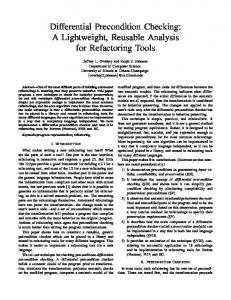
and (9) it is seen that the force-induced strains are of opposite sign and that the temperature-induced strains are of the same sign. The relative difference frequency of the centre-bossed force sensor can therefore be expressed by eqns. (7(a)-(b)). Note that in the previous equations, stress stiffening occurring at large deflections is not taken into account. Stress stiffening affects the sensitivity, since it will alter the force-to-strain conversion in eqn. (8). A further analysis of eqn. (9) indicates that the effect of differential thermal expansion can be suppressed by lowering h,/h, or E,,,/E,, (i.e., a more flexible mount), or trivially, by a better matching of the thermal expansion coefficients of the mount and bridge material. Some of these effects are illustrated in Fig. 4. Depending on the sign of the first term in eqn. (9), the thermal strains can be tensile or compressive (see also the magnified view in Fig. 4). Theoretically, zero thermal strain is achieved if the following condition is satisfied:
(10)
Experimental Results and Discussion To verify the basic principles of the bossed differential design, a macroscopic model made
(9)
where c+,is the thermal expansion coefficient of the sensor chip material, E,,, and ~1, are the Young’s modulus and the thermal expansion coefficient of the mount material, L, and h, the length and thickness of the mount, and H is the distance between the neutral axes of the bridge and the mount, H = D + 0.5h,,+ OSh,, where D is indicated in Fig. 3. From eqns. (8)
out of brass was used for obtaining experimental data. A perspective view of the test structure is shown in Fig. 5, also indicating its dimensions. Two resonator pairs are shown, one pair on each side of the boss. Only one pair was used for the measurements. The structure was tested as a force transducer with the load applied to the centre boss. The
390
FORCE-N
100
10' NORMALIZED
10'
MOUNTTHICKNESS
10'
103 (h,/
hJ
Fig. 4. Strain induced by differential thermal expansion vs. the normalized mount thickness computed from eqn. (9). The meaning of the symbols is explained in Figs. 2 and 3. The magnified view shows points of zero strain, which can be computed from eqn. (IO).
Fig. 5. Sketch of the brass structure used for the measurements. The dimensions are expressed in millimeters. Two resonator pairs are shown. A piezo-element (Philips PXE-5), attached at the centre of each gauge, is used for excitation and detection of the vibration. Selfoscillating circuits are used to measure the resonance frequency of the gauges.
resonators were not sealed in evacuated cavities. A single piezo-element (Philips PXE-5) attached at the centre of the gauge, was used for both excitation and detection of the vibration (one-port approach [ 111). Self-oscillating circuits were used to measure the resonance frequency of the resonators. The piezo-element was used as the frequency-determining impedance of the oscillator. Figure 6 shows the measured frequency of the resonator adjacent to the boss (f,) and of the resonator adjacent to the frame of the structure (fJ as a function of the applied force. The difference frequency is also shown. Mea-
Fig. 6. Force response of the brass structure of Fig. 5, showing the resonance frequency of the resonators of one pair, together with the difference frequency as a function of the applied force.
sured sensitivities are -4.2 Hz/N, 4.3 Hz/N and 8.5 Hz/N for resonator 1, resonator 2 and the differential design respectively. Conforming to the expectations, the shift in the difference frequency is roughly twice the shift in frequency of the individual resonators. To compare the experimental results with the theory, eqn. (8) needs to be corrected for the relatively large values of the thickness of the resonators and of the gap underneath the resonators. This yields a force-induced strain of 7.8 ppm/N (& = 100 GPa and v = 0.34 [lo]). Assuming zero residual strain, eqn. (2) predicts a gauge factor of 208. This results in a predicted force-induced frequency shift of 0.16%/N (relative) or 7.6 Hz/N (absolute) at a predicted base frequency f0 of 4668 Hz (p = 8500 kg/m3 [lo]). Discrepancies from the experiments can be explained by uncertainties in the dimensions, the residual strain and the material properties. To obtain data on the intrinsic temperature dependence, i.e., the first term in eqn. (6) the bare structure from Fig. 5, i.e., without the mount, was put in a temperatureregulated oven. Figure 7 shows the shift of the resonance frequency as a function of temperature in the range 30-90 “C. An intrinsic temperature dependence of approximately - 152 and - 165 ppm/“C is found for resonators 1 and 2, respectively. This is in close agreement with eqn. (5), which predicts an intrinsic dependence of - 158 ppm/“C, substituting a
1.. 30
. 40
50
60
70
60
I 90
-20 30
40
TEMPERATURE _ ‘C
50
60
70
60
90
TEMPERATURE - ‘C
(a)
Fig. 7. Measured frequency shifts as a function of temperature due to the intrinsic temperature dependence of the brass structure of Fig. 5.
coefficient of Young’s modulus of -335 ppm/“C [ 121 and a thermal expansion coefficient of 19 ppm/“C [lo]. The temperature dependence of the difference frequency is reduced with more than a factor of seven compared to the dependence of the single resonators. Since the force sensitivity is doubled for the difference frequency, the relative improvement for the intrinsic temperature dependence is by more than a factor of 14. Equation (7(a)) predicts an intrinsic temperature dependence of the difference frequency equal to Go As,(Aintr./fo), or in other words a reduction of a factor l/G, AcOdcompared to the single resonator design. The measured reduction factor of seven can be fully explained by this term in the case of a mismatch in residual strain of 0.07% (taking Go = 208). Other explanations for the observed non-zero intrinsic temperature dependence of the differential design are related to a mismatch in dimensions of the two resonators (not accounted for in the theoretical analysis), to a non-zero thermal strain AL+# 0 (see second term in eqns. (7(a)-(b)) or to a mismatch in thermal strain of the two resonators (A&T,#A&n). Finally, the effect of differential thermal expansion was investigated by mounting the brass structure of Fig. 5 on a steel bar and measuring the frequency shifts of the resonators as a function of the ambient temperature. In order to verify the theory (eqn. (9)), temperature
=Af,
-1401.
.\ 30
(b)
40
50
60
TEMPERATURE
70
60
90
- ‘C
Fig. 8. Measured frequency shifts as a function of temperature for the brass structure of Fig. 5, mounted on a steel bar for different thicknesses: (a) mount thickness 2 mm, (b) mount thickness 22 mm.
which predicts compressive as well as tensile strains to occur depending on the device parameters, two experiments were done, one with a relatively thin steel bar (2 mm) and another with a thick bar (22 mm). The experimental results are shown in Fig. 8(a) and (b) for the thin and the thick mount, respectively. Opposite signs for the frequency shifts are observed, which is in agreement with the theory. For the thin mount, the measured sensitivities are 230 ppm/“C and 260 ppm/“C for resonators 1 and 2, respectively. After correcting for the known intrinsic dependence, the effect due to differential thermal expansion alone is obtained, yielding 382 ppm/“C and 425 ppm/“C, respectively. Taking account of the large values of the thickness of the resonators and of the gap underneath the resonators will modify eqn. (9). The modified
392
equation predicts a thermal strain A.+ = 0.208 (cl,,- a,) AT. Assuming a gauge factor of 208 and taking the average value of the measured temperature sensitivity, i.e., 404 ppm/“C, the measurements and the theory agree for (c(~- a,) = 9 ppm/“C, which is within the possible data range of I-11 ppm/“C according to ref. 12. For the thick mount, the measured sensitivities are, after correction for the known intrinsic dependence, -448 ppm/ “C and -222 ppm/“C for resonators 1 and 2, respectively. The modified eqn. (9) predicts a thermal strain AeT = -0.56(ab - a,) AT, which, under the same assumptions as for the thin mount, yields (cl,,- a,) = 3 ppm/“C. This is still within the data range according to ref. 12, but a factor of three smaller than the value found for the thin mount. A possible explanation for the latter discrepancy is a change of the gauge factor (AC, in eqn. (6)) as a result of a shift of the built-in strain, occurring while mounting the structure. In the difference frequency, the effect of differential thermal expansion alone is reduced by factors of 10 and two for the thin and thick mounts respectively, implying a relative improvement of the load sensitivity of 20 and four, respectively. The fact that the difference frequency still exhibits differential thermal expansion effects might be caused by a non-zero second term in eqns. (7(a)-(b)), i.e., a different value for the strain sensitivity of the two resonators, Assuming (ab - CX,)= 6 ppm/“C (i.e., the average of the possible data range [ 12]), a AGOd of -58, i.e., a relative shift of approximately - 28%, would explain the observed reduction factor of two in the case of the thick mount. A difference in gauge factor shift of 58 can be caused by a difference in strain levels (A& of 0.07%, which is not unlikely for the brass model.
Conclusions This paper has demonstrated the feasibility of a differential resonator design using a bossed structure. Theoretically, the relative intrinsic temperature dependence and differ-
ential thermal expansion effects can be eliminated, while the sensitivity to the load to be measured is doubled. Mismatches in the resonators, resulting in a temperature-dependent offset as well as in a temperature-dependent sensitivity, were accounted for in the analysis. Experimental data obtained from a macroscopic brass model indicate that a mismatch in residual strain can result in a great loss of the rejection of temperature effects. The resuits of this research are directly applicable to micromachined structures in silicon,
Acknowledgements The authors wish to acknowledge the support of Johnson Controls Nederland B.V. and of the Controls Research group of Johnson Controls Inc., Milwaukee.
References R. M. Langdon, Resonator sensors-a review, J. Phys. E: Sci. Instrum., 18 (1985) 103-115. K. Ikeda, H. Kuwayama, T. Kobayashi, T. Watanabe, T. Nishikawa and T. Yoshida, Silicon pressure sensor with resonant strain gauge built into diaphragm, 7th Sensor Symp., Tokyo, Japan, 1988, pp. 55-58. H. Guckel, J. J. Sniegowski, T. R. Christenson and F. Raissi, The application of fine-grained, tensile polysilicon to mechanically resonant transducers, Sensors and Actuators, A21-A.23
(1990) 346-351.
H. A. C. Tilmans, S. Bouwstra, J. H. J. Fluitman and S. L. Spence, Design considerations for micromechanical sensors using encapsulated built-in resonant strain gauges, Sensors and Actuators A, 25-27 (1991) 79-86. G. Kowalski, Miniature pressure sensors and their temperature compensation, Sensors and Actuators, II (1987) 367-376. J. J. Sullivan, Development of variable capacitance pressure transducers for vacuum applications, J. Vat. Sci Technol. A, 3 (3) (1985) 1721-1730.
E. Stemme and G. Stemme, A balanced resonant pressure sensor, Sensors and Actuators, A21 -A23 (1990) 336-341. 8 W. C. Albert, Vibrating quartz crystal beam accelerometer, Proc. 28th ISA Int. Instrument. Symp., Las Vegas, NV, U.S.A., May 3-6, 1982, pp. 33-44. 9 H. R. Zulhger, Precise measurement of small forces, Sensors and Actuators, 4 (1983) 483-495.
393
10 J. M. Gere and S. P. Timoshenko, Mechanics of Materials, Van Nostrand Reinhold, Reading, U.K., 2nd edn., 1988. 11 M. W. Putty, S.-C. Chang, R. T. Howe, A. L. Robinson and K. D. Wise, One-port active polysilicon resonant microstructures, Proc. IEEE Micro
Eleetro Mechanical
Systems
Workshop, Salt L.&e
City, UT, U.S.A., Feb. 1989, pp. 60-65. 12 Landolt-Biimstein, Zahlenwerte und Funktionen, aus Physik Chemie Astronomie Geophysik Technik, Vol. II, Part I, Mechanische-thermische Zustandsgriissen, Springer, Berlin, 6th edn., 1971, p. 835.