search is that the capture devices are lightweight, cheap, low power and have the .... side of a laptop computer which shows the prompts for the subject to read.
A DIGITAL MICROPHONE ARRAY FOR DISTANT SPEECH RECOGNITION Erich Zwyssig1,2 , Mike Lincoln1 and Steve Renals1 1
Centre for Speech Technology Research, University of Edinburgh, Edinburgh, EH8 9AB, Scotland UK 2 EADS IW UK Ltd., Appleton Tower, 6th Floor, Edinburgh, EH8 9LE, Scotland UK ABSTRACT
In this paper, the design, implementation and testing of a digital microphone array is presented. The array uses digital MEMS microphones which integrate the microphone, amplifier and analogue to digital converter on a single chip in place of the analogue microphones and external audio interfaces currently used. The device has the potential to be smaller, cheaper and more flexible than typical analogue arrays, however the effect on speech recognition performance of using digital microphones is as yet unknown. In order to evaluate the effect, an analogue array and the new digital array are used to simultaneously record test data for a speech recognition experiment. Initial results employing no adaptation show that performance using the digital array is significantly worse (14% absolute WER) than the analogue device. Subsequent experiments using MLLR and CMLLR channel adaptation reduce this gap, and employing MLLR for both channel and speaker adaptation reduces the difference between the arrays to 4.5% absolute WER. Index Terms— digital microphone array, speech recognition, WSJCAM0, MEMS microphone 1. INTRODUCTION Automatic Speech Recognition (ASR) research has focused on tasks in which the speech is recorded using close-talking headset microphones or from telephone handsets. In recent years, however, there has been an increasing focus on distant speech recognition [1] in which the speech is captured by multiple distant microphones, typically in an array configuration. Work on distant speech recognition has been inspired by some recent intense efforts in the recognition of speech in meetings and in seminars [2, 3] and through international evaluation campaigns such as the NIST RT evaluations [4] or the Speech Separation Challenge II (http://homepages.inf. ed.ac.uk/mlincol1/SSC2/). This work has focused largely on the use of microphone arrays with a known geometry, to which beamforming algorithms may be applied in order to provide an enhanced version of the input based on the location of the speaker. The work of Omologo [5] and McCowan [6] indicated that microphone arrays can be an effective alternative to close-talking microphones for single talker ASR in environments characterised by noise or multiple acoustic sources. For multitalker environments such as meetings, talker overlap is extremely common. In such environments, the directional nature of the array allows discrimination between speakers leading to improved ASR performance for overlapping speech [7]. More recently, large vocabulary ASR systems [8, 9] have been developed for the recognition of multiparty Supported by European IST Programme Project FP6-033812 (AMIDA). This paper only reflects the authors’ views and funding agencies are not liable for any use that may be made of the information contained herein.
speech in meetings, with a word error rate (WER) only a few percent higher than that obtained using high quality close-talking microphones. A major motivation for the use of microphone arrays to record speech for speech recognition is that of intelligent instrumented environments. In such environments, multiple distant microphones are used to capture the acoustic scene: a pervasive vision for such research is that the capture devices are lightweight, cheap, low power and have the potential to be massively scalable. To date, microphone arrays for instrumented environments have been constructed using discrete analogue microphones (typically omni directional lapel microphones). Although such microphones can provide a very high quality signal, they bring a number of disadvantages: • Cost: individual microphones typically cost at least several tens of dollars. • Size: the microphones themselves may be relatively bulky requiring an enclosure or mount. • Audio interface: the analogue signal from the microphones requires amplification and analogue to digital conversion before processing by computer. These steps are typically integrated in the audio interface, making the device expensive, relatively high power, and too large to be easily portable. Recent work has attempted to integrate the components of an array based on analogue microphones in a single unit, and has shown promising performance in a simple speech recognition experiment [10]. However the system still requires amplifiers and analogue to digital converters (ADCs), which means that it is still relatively bulky and expensive. MEMS (Micro Electro Mechanical System) microphones are essentially a ‘microphone on a chip’ with the pressure sensitive membrane being etched directly onto the silicon, and usually accompanied by a matched pre-amplifier on the same chip. Research and development of MEMS microphones has been ongoing for some 20 years in order to manufacture a product suitable for customer applications. Requirements such as operation at standard supply voltages [11], support of surface mount packaging [12], use of standard CMOS processes during manufacture [13], and acceptable signal to noise ratio [14] have recently been realised and have led to a breakthrough in MEMS microphone production and usage today. Recent advances in MEMS microphone technology have resulted in the integration of the ADC on the same chip as the microphone and amplifier, producing a digital microphone in which the output of the chip is a Pulse Density Modulated (PDM) version of the incident acoustic signal. A microphone array made from such devices would not require external amplifiers or ADCs and the mass production of MEMS chips would result in an extremely low cost for the array. Because the audio signal is immediately converted to the digital domain, the system has the potential to be more robust to noise than its analogue alternative. The array could be made in an extremely small form factor, or directly integrated into the PCB of a host device - for
'LJLWDO�0(06� 0LFURSKRQH�$UUD\
2.2. FPGA ;LOLQ[�6SDUWDQ��$�)3*$
'RZQVDPSOH DQG�&RQYHUW� WR�3&0
$&¶��� ,QWHUIDFH
786%����$� 86%� VWUHDPLQJ� FRQWUROOHU
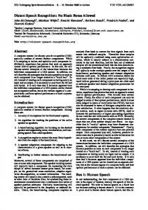
Fig. 1. Overview of Digital MEMS Microphone Array Architecture
instance the MEMS chips could be mounted on the outer edge of an LCD display for integration in laptops, or in a conference phone for use in meetings. This paper describes the design and implementation of a prototype eight element microphone array built using digital MEMS microphones. To our knowledge no similar arrays of more than two elements have been reported. We have carried out large vocabulary speech recognition experiments, comparing results using speech captured by the digital microphone array with speech captured using an existing analogue microphone array. Our speech recognition experiments have built upon the protocol developed by Lincoln et al. [15], using the WSJCAM0 corpus [16] for training and the microphone array data for development and testing. We report results that indicate that if adaptation algorithms (such as MLLR) are not applied, then the digital microphone array results in much higher word error rates than the analogue array. However, after adaptation (using mean-only MLLR), we find that the gap in accuracy between the digital and analogue arrays is much smaller.
2. THE DIGITAL MICROPHONE ARRAY A schematic overview of the digital microphone array architecture is shown in figure 1. The system comprises three main components: the microphone array itself, a Xilinx FPGA and a Texas Instruments USB streaming controller.
2.1. The Array The array contains eight omnidirectional digital MEMS microphones (Knowles Acoustics SPM0205HD4) mounted on small daughter boards, which are located equidistantly around a 20cm diameter circle on a larger, circular PCB. The larger PCB provides connections to each of the microphone outputs and clock inputs. Mounting the microphones on daughter boards allows the microphones to be easily replaced if they do not match the published specifications. Figure 2 shows the constructed microphone array.
We use a Xilinx Spartan 3A FPGA in the implementation of the digital microphone array. This device was chosen because it is large enough to implement all the required functionality required but is small enough to be simulated and programmed using freely available software. The FPGA performs two functions. The ADC on each MEMS chip is a sigma-delta oversampling device, outputting a binary PDM signal at 64fs = 1.024MHz, which is 64 times the required sampling frequency, fs = 16kHz. This signal is downsampled and converted to PCM before it is transmitted over an AC’97 interface to the USB streaming controller. The FPGA performs this downsampling and format conversion and also implements the AC’97 interface between the input audio signals and the USB streaming interface. The downsampling is performed using a series of decimation filters. The first, a Cascaded Integrator-Comb (CIC) filter, downsamples from 64fs to 8fs . A series of 3 FIR filters is then used to sequentially reduce the sample rate by a factor of 2. The filters are designed using the Matlab filter design toolbox and Verilog HDL code generated by the Matlab filter design HDL coder for implementation on the FPGA. Because of the restricted number of multipliers on the chip, the FIR filters are implemented in stereo, with the individual microphone channels being multiplexed before the filtering operation, and de-multiplexed after. The PCM data at the required sample frequency is buffered before being passed to the AC’97 interface. The FPGA also generates the clock signal for the microphones and implements a simple volume control which can be adjusted via the AC’97 interface. The data flow on the Xilinx chip is shown in figure 3 and further details can be found in [17]. 2.3. USB Streaming Interface The Texas Instruments TUSB3200A USB streaming controller is used as the interface between the FPGA, which delivers audio via the AC’97 interface, and the PC. The device is used on the TI evaluation board and we extended the supplied firmware (designed for stereo playback and mono recording) to allow the simultaneous recording of 8 channels. When connected to the PC, the device appears as an eight channel audio input device and can be accessed by standard audio recording software.1 3. SPEECH RECOGNITION EXPERIMENTS In order to investigate whether the use of digital microphones affects the performance of the array for speech recognition tasks, talkers were simultaneously recorded using both the digital and an analogue array and their performance on a large vocabulary speakerindependent speech recognition task was compared. 3.1. Recording Setup and Task The recordings were made in the Instrumented Meeting Room in the University of Edinburgh. The analogue array consisted of 8 Sennheiser MKE-2P omnidirectional lapel microphones arranged in a circular configuration of 20cm diameter (identical to the configuration of the digital array). The array was connected to a PC via a MOTU 896 HD mic pre-amp and firewire audio interface, and
(a) Microphones on daughter boards (b) Complete microphone array Fig. 2. The digital MEMS microphone array
1 In practice both Linux and Windows operating systems do not currently recognise 8-channel USB audio devices without additional driver code. We used a time domain multiplexing system, in which up to twelve 16 kHz channels were multiplexed in four 48 kHz slots (Ubuntu Linux could recognise up to 7 channels), with demultiplexing carried out in software on the PC.
ELQ
0LF LQ
ELQ
�¶V&
&,&
�¶V&
&,&
),5�� 0X[
),5�� '63�&ON 0LF &ON
),5��
9RO
),)2
&ORFN� 0DQDJHU
$&¶��� ,QWHUIDFH
'DWD�2XW 'DWD�,Q 0&ON )6\QF %&ON
&RQWURO
Fig. 3. Digital MEMS microphone array DSP implementation on FPGA
Plogue Bidule software was used to record the analogue array to disk. The system outlined in section 2 was used for the digital recordings. The arrays were placed on the meeting room table, either side of a laptop computer which shows the prompts for the subject to read. The subjects sat directly in front of the laptop, equidistant from each array. The analogue system records at 48KHz, and Matlab’s resample command was used to downsample the audio files to 16KHz before processing. The recording setup was based on that used for the MC-WSJ-AV recordings [15].2 Six male and six female speakers were recorded reading sentences from the WSJCAM0 [16] test and development sets. All participants were native British English speakers. The set of prompts for each speaker was selected from one of the sets used in WSJCAM0, and typically contained 17 TIMIT style sentences (for adaptation), 40 sentences from the 5,000 word (closed vocabulary) sub corpus of WSJCAM0 and 40 sentences from the 20,000 word (open vocabulary) sub corpus. Each audio channel was recorded as a single wav file, and the files were manually split into individual sentences for recognition. 3.2. Beamforming Each array produces 8 wav files, one for each microphone, and a beamforming frontend system is then used to enhance the files prior to recognition. The beamforming frontend is identical to that used by the AMI entry to the Spring 2005 NIST Rich Transcription evaluation and is fully described in [18]. It consists of a Wiener filter which removes stationary noise from each channel, followed by a filter and sum beamformer. Delay estimates for the filters are calculated on a frame by frame basis by identifying the peak in the generalised cross correlation between channels, meaning that the beamformer effectively tracks and enhances the loudest sound source in the room. 3.3. Recogniser The speech recognition system is a standard GMM/HMM recogniser developed using HTK on the WSJCAM0 training data. The system consists of approximately 11,000 tied-state triphones with three emitting states per triphone and 6 mixture components per state. 52element feature vectors were used, comprising 13 MFCCs (includ2 Note that the Instrumented Meeting Room has changed location since [15], and the new room is much less reverberant.
ing the 0th cepstral coefficient) with their first, second and third order derivatives. The vocabulary was the standard 5,000 word vocabulary used for the WSJ0 5,000 word closed vocabulary task. We used the standard MIT-Lincoln Labs 5k Wall Street Journal trigram language model, and pronunciations were obtained from the dictionary generated for the AMI NIST RT05S system [18]. The baseline system, with no adaptation, gives 9.9% WER on the WSJCAM0 si dt5a 5,000 word task. Due to time constraints, experiments were conducted on the 5k word sentences only. Preliminary experiments on the 20k task show similar patterns of performance, albeit with increased WER due to the increased vocabulary size. 3.4. Baseline Results The top row of table 1 gives baseline word error rates for the analogue and digital arrays. The results show that the digital array recordings result in a substantially increased WER compared with that obtained from the analogue array. The signal to noise ratio of the digital microphones is lower than that of the analogue microphones and this, coupled with the lower performance of the on chip amplifiers and ADCs compared with those used for the analogue array, means that the audio from the digital array is less well matched to the recognition models which are trained on speech from high quality analogue headset microphones. This results in the observed decrease in accuracy. 3.5. Adaptation In order to address the mismatch between training and test data, an experiment was conducted in which the recognition models are adapted to the acoustic properties of the recordings. A two pass maximum likelihood linear regression (MLLR) [19] adaptation of the model means was used. The first pass computes a single global transform for all model mean vectors. This transform is then used to compute improved frame/state alignments for the second pass, which computes more specific transforms using a regression class tree generated from the training data. We also performed constrained MLLR (CMLLR) adaptation [20] of the means and variances. We adapted the models to both the channel and to individual speakers. To perform channel adaptation, we pooled the 17 adaptation sentences recorded by each speaker to produce transforms spe-
Table 1. %W.E.R on 5K WSJCAM0 task for 6 male and 6 female speakers Adaptation Technique None MLLR Channel CMLLR Channel MLLR Speaker and Channel
Analogue 30.2 22.6 21.3 18.2
Male Digital 40.7 27.4 26.3 20.7
∆ 10.5 4.7 5.0 2.5
cific to the digital array and to the analogue array. Recognition was then performed on the 5k word data from the matched array and the results are shown as ‘Channel’ in table 1. As expected, the adaptation gives decreases in WER for both analogue and digital arrays. More importantly, the absolute difference in WER between the analogue and digital arrays was reduced by nearly 50%, from 14.3% to 7.4%. This suggests that, although the quality of the output from the digital array is lower than that of the analogue array, and therefore not as closely matched to the close talking models, it still contains much of the speech information required to perform recognition providing the models are matched to the microphones. Performing CMLLR channel adaptation resulted in further decreases in WER. Finally we performed experiments in which the models were adapted to the speaker and to the channel, by defining the adaptation sets as those sentences recorded from the same speaker on the same array. In this case the absolute difference in WER between the analogue and digital arrays was further reduced by about 40% to 4.5%.
Analogue 36.9 22.2 20.7 19.4
[7]
[8]
[9]
[10]
[11]
4. CONCLUSIONS AND FUTURE WORK [12] In this paper we have presented the design and implementation of an 8 element microphone array using digital MEMS microphones, the first of its kind. The array has been tested in terms of the word error rate it achieves on a speech recognition task. Although the training data was recorded using high quality analogue microphones we found that recognition accuracy from the digital array was close (although significantly worse) to that achieved from an analogue array when standard channel and speaker adaptation techniques were used. The device has the potential to be smaller, cheaper and more flexible than typical analogue arrays. 5. REFERENCES [1] Matthias W¨olfel and John McDonough, Distant Speech Recognition, Wiley, 2009. [2] Steve Renals, Thomas Hain, and Herv´e Bourlard, “Recognition and interpretation of meetings: The AMI and AMIDA projects,” in Proc. IEEE Workshop on Automatic Speech Recognition and Understanding (ASRU ’07), 2007.
[13]
[14]
[15]
[16]
[17]
[3] Alexender Waibel and Rainer Stiefelhagen, Computers in the Human Interaction Loop, Springer, 2009. [4] Jonathan Fiscus, Jerome Ajot, and John Garofolo, “The rich transcription 2007 meeting recognition evaluation,” 2008, vol. 4625 of LNCS, pp. 373–389, Springer. [5] M. Omologo, M. Matassoni, and P Svaizer, “Speech recognition with microphone arrays,” in Microphone Arrays, M. Brandstein and D. Ward, Eds. 2001, pp. 331–353, Springer. [6] I. McCowan, C. Marro, and L. Mauuary, “Robust speech recognition using nearfield superdirective beamforming with
[18] [19]
[20]
Female Digital 55.1 32.2 29.7 25.9
∆ 18.2 10.0 9.0 6.6
Analogue 33.6 22.4 21.0 18.8
Average Digital 47.9 29.8 28.0 23.3
∆ 14.3 7.4 7.0 4.5
postfiltering,” in Proc. ICASSP 2000, 2000, vol. 3, pp. 1723– 1726. D. Moore and I. McCowan, “Microphone array speech recognition: Experiments on overlapping speech in meetings,” in Proc. ICASSP 2003, 2003. T. Hain, L. Burget, J. Dines, G. Garau, M. Karafiat, M. Lincoln, J. Vepa, and V. Wan, “The AMI system for the transcription of speech in meetings,” in Proc. IEEE ICASSP–07, 2007. A. Stolcke et al, “The SRI-ICSI spring 2007 meeting and lecture recognition system,” in Multimodal Technologies for Perception of Humans. 2008, vol. 4625 of LNCS, pp. 450–463, Springer. Qi Li, Manli Zhu, and Wei Li, “A portable USB-based mirophone [sic] array device for robust speech recognition,” in Proc. ICASSP 2009, 2009, vol. 3, pp. 1301–1304. J. W. Weigold, T. J. Brosnihan, J. Bergeron, and X. Zhang, “A MEMS condenser microphone for consumer applications,” in IEEE International Conference on MEMS, 2006, pp. 86–89. M. Brauer, A. Deh´e, T. Bever, S. Barzen, S. Schmitt, M. F¨uldner, and R. Aigner, “Silicon microphone based on surface and bulk micromachining,” J. Micromech. Microeng, vol. 11, pp. 319–322, 2001. J. Neumann and K. Gabriel, “CMOS-MEMS membrane for audio-frequency acoustic actuation,” Sensors and Actuators A: Physical, vol. 95, no. 2-3, pp. 175 – 182, 2002. J. J. Neumann Jr and K. J. Gabriel, “A fully-integrated CMOSMEMS audio microphone,” in Intl. Conf. on Transducers, Solid-State Sensors, Actuators and Microsystems, 2003, vol. 1, pp. 230–233. M. Lincoln, I. McCowan, J. Vepa, and H. K. Maganti, “The multi-channel Wall Street Journal audio visual corpus (MCWSJ-AV): specification and initial experiments,” in Proc. IEEE ASRU, 2005, pp. 357–362. T. Robinson, J. Fransen, D. Pye, J. Foote, and S. Renals, “WSJCAM0: A British English speech corpus for large vocabulary continuous speech recognition,” in Proc. IEEE ICASSP, Detroit, 1995, pp. 81–84. E. Zwyssig, “Digital microphone array - design, implementation and speech recognition experiments,” MSc. thesis, University of Edinburgh, 2009. T. Hain et al., “The 2005 AMI system for the transcription of speech in meetings,” in NIST RT05 Workshop, 2005. C. Leggetter and P. Woodland, “Maximum likelihood linear regression for speaker adaptation of continuous density HMMs,” Computer, Speech, and Language, vol. 9, pp. 171–185, 1995. M. J. F. Gales, “Maximum likelihood linear transformations for HMM-based speech recognition,” Computer Speech and Language, vol. 12, no. 2, pp. 75–98, 1998.