product of the angular neutron den,sity and the neutron velocity. ..... solution for the flux at any point s when _t0 is known oaadproperties are constant. Thus, the.
WS_-YS"- 92- 269 , DE92 040165
:
A DISCRETE ORDINATES APPROXIMATION TO THE NEUTRON TRANSPORT EQUATION APPLIED TO GENERALIZED GEOMETRIES (U) by M, D. DeHart Westinghouse Savannah River Company Saveamah River Site Aiken, South Carolina 29808 DISCLAIMER of work spon_red by an agency of the United States Government nor any agency thereof, t_or any of their or implied, or assumes any legal liabi|ity or rcsponsi ...... usefulnesso,f any information, apparatus, p;oduct, or
:.....
process disclosed, or represents that its use would I_ot infringe privately owned right_. Refer .... enc¢ herein to any specific commercial product, process, or service by trade name, trsdemark,
.Apaper submitted to the Office of Graduate Studies at Texas A &M University in partial fulfillment of the requirements for the degree of DOCTOR OF PHILOSOPHY December, 1992
_k._': _,\:
_ '_ _ _!
_i
' :"
__ " '
"' ' ,
_ _*_
"_
,_._
[
[+,
;,, .. •
_ ', +_
., '
manufacturer, or o.therwis¢ dots not necessarily constitute or imply its endorsement, rccommendation, or favoring by the United States Government or any agency thereof. The views and opinions of authon _,xpre_xl herein do not nccc-_afily state or reflect thole of t_e United States Oovernme.t or any agency thereof.
'_,
:
This report was prepared as an aoco,unt Government. Neither the United State, s employees, makes any warranty, express bility for th,¢ accuracy, completeness, or
_,_ ;......
This report was prepared in connection with work done under Contract No. DE-AC09-89SR 18035 with the U'.S. Department of Energy. By acceptance of this report, the publisher and/or recipient acknowledges the U.S. Government's right to retain a nonexclusive, royalty-free license in and to any copyright coveting this report, along with the tight to reproduce and to authorize others to reproduce all or part of the copyrighted report.
,...."_"__ ,;_.
DISTRIBUTION OF THIS DocuMENT IS UNLIMITED
!
i,..._ ................
A DISCRETE ORDINATES APPROXIMATION TO THE,"NEUTRON TRANSPORT EQUATION APPLIED TO GENERALIZED GEOMETRIES
A Dissertation by MARK DAVID DeHART
Submitted to the,Office of Graduate Studies of Texas A&M University in partial fulf'fllment of the requirements for the degree of DOCTOR OF PHILOSOPHY
December 1992
Ivlajor Subject: Nuclear Engineering
DISCI, AIMER This report was prepared as an account of work sponsored by an agency of the United States Government. Neither the United States Government nor any agency thereof, nor any of their employees, makes any warranty, express o,' implied, or assumes gay legal liability or responsibility for the accuracy, completeness, or usefulness of any infomaation, apparatus, product, or process disclosed, or represents that its use would not infrh_ge privately owned rights. Reference herein to any specific commercial product, process, or service by trade name, trademark, manufacturer, or otherwise does not necessarily constitute or imply its endorsement, recommendation, or favoring by the United States Government or any agency thereof. The views and opinions of authors expressed herein do not neeessmily state or reflect those of the United States Government or any agency thereof. This report has been reproduced directly from the best available copy.
Available to DOE and DOE contractors from the Office of Scientific and Technical Information, P.O. Box 62, Oak Ridge, TN 37831; prices available from (615) 576-8401, F'rs 626-8401.
Available to the public from the National Technical Information Service, U.S. Department of Commerce, 5285 Port Royal Rd., Springfield, VA 22161.
111
ABS'IRACT .....
A Discrete Ordinates Approximation to the Neutron Transport Equation Applied to Generalized Geometries. (December 1992) Mark David DeHart, B.S., Texas A&M University M.S., Texas A&M University Chair of Advisory Committee: Dr. Theodore A. Parish A method for applying the discrete ordinates method for solution of the neutron
ta'ansport equation in arbitrary two-dimensional meshes has been developed. The finite difference approach normally used to approximate spatial derivatives in extrapolating angular fluxes acrcss a cell is replaced by direct solution of the characteristic form of the transport equation for each discrete direction. Thus, computational cells are not restricted to the traditional shape of a mesh element within a given coordinate system. However, in terms of the treatment of energy and _mgular dependencies, this method resembles traditional discrete ordinates techniques. Using the method developed here, a general two-dimensional space can be approximated by an irregular mesh comprised of arbitrary polygons, The method of characteristics, originally developed to eliminate negative fluxes encountered in many f'mite difference approxinmtions, had been previously applied to regular cell structures in multiple dimensions aa_dvarious coordinate systems. In such geometries, the geometrical relationships between sides were determined analytically and incorporated directly into the numerical model. However, the present work makes no assumptions about the orientations or the number of sides in a given cell, and computes ali geometric relationships between each set of sides in each cell for each discrete dh'ection. A set of non-reen_trant polygons can therefore be used to represent any given two dimensional ., |
space. Results for a number of test problems have been compared to solutions obtained from traditional methods, with good agreement. Comparisons include benchmarks against
m
_a
i
iv
analytical results for problems with simple geometry, as well numerical results obtained from traditional discrete ordinates methods by applying the ANISN and TWOTRAN computer programs. Numerical results were obtained for problems ranging from simple one-dimensional geometry to complicated multidimensional configurations. These results have demonstrated the ability of the developed method to closely approximate complex geometrical configurations and to obtain accurate results for problems that are extremely difficult to model using traditional methods.
DEDICATION This work is dedicated to my wife, Leigh. Her patience, understanding and love over the long road leading to this point imde the path seem much less rocky; her encouragement and willingness to listen to my problems helped to sustain my efforts; and the daughter she has given us has taught me that miracles are possible.
vi ACKNOWLEDGEMENTS
I wish to express my sincere and profound gratitude to Ron Pevey and Ted Parish, both of whom provided invaluable support and insight in my endeavors. Their guidance, encouragement, technical assistance and senses of humor were invaluable assets. I also wish to acknowledge the support given to me by the United States Department of Energy, the Westinghouse Savannah River Company, and most importantly, by several members of my direct management and by my colleagues within the Savannah River Technology Center, who provided support on various levels through the completion of this project. Most notable are Drs. John Menna, AI Garrett, Nick Kuehn, Courtney Apperson, Mel Buckner, and Joe Spencer, each of whom helped to make this project possible. The professionals and staff of tile Applied Reactor Technology Group also provided significant feedback; Neal Askew, John Metzger, Gwen Gill and Bruce Hardy were always willing to listen to me think out loud. For their hands-on assistance in helping me to learn, set up and run various programs, or for performing or assisting in many of the benchmark calculations, I especially wish to thank Chien-Hsiang Chen, Roger Webb, Sam Painter, James Taylor, and Khalid Mansour. Finally, I wish to acknowledge and thank Drs. Marvin Adams, Erian Baskharone, Wesley Bolch, and Paul Nelson, for their help, encouragement,
and valuable comments. I
feel privileged to have had a research committee which took a proactive interest in my work, well beyond the minimum requirements of a committee member.
vii
TABLE
OF CONTENTS Page
ABSTRACT
........................................................................................
iii
DF23ICATION ......................................................................................
v
ACKNOWLEDGEMENTS
vi
.......................................................................
TABLE OF CONTENTS ........................................................................
vii
LIST OF TABLES .................................................................................
ix
LIST
x
OF
FIGURES ................................................................................
CHAPTER I
INTRODUCTION ...................................................................... Background ........................................................................ The Method of Characteristics ..................................................
II
LITERATURE
REVIEW ...............................................................
Discrete Ordinates Methods for Generalized Geometries .................. Development of Characteristics-Based Methods ............................ Ili
THEORY ................................................................................ Fundamental Concepts and Assumptions .................................... Angular Hux at a Cell Boundary .............................................. Relationships Between Cell Boundaries ..................................... Mapping a Characteristic Vector into the Two-Dimensional Problem Domain ........................................................................... Neutron Balance Within a Computational Cell .............................. Determination of the Source Term ............................................
:
IV
APPLICA'HON ..................................................................... Geometric Descriptions ........................................................ Intracell Relationships .......................................................... Order of Cell Solution .......................................................... Leakage Coefficients ........................................................... Iterative Solution ................................................................ Memory Management ..........................................................
V
RESULTS
..............................................................................
Case 1: Two Region, Two Group Slab ..................................... Case 2: Ray Effects in a Square Non-Multiplying Medium with a Localized Source ......................................................
1 1 3 7 ..7 12 18 18 22 27 31 32 33 36 36 40 46 47 48 51 55 55 59
0))
VIII
Case 3: Escape Probability for an Infinite Absorbing Medium ........... 64 Case 4: Solution in a Composite Cylinder with Azimuthal Symmetry... 67 Case 5: Application in a Non-Orthogonal Geometry ....................... 75 VI
CONCLUSIONS
......................................................................
83
Strengths and Weaknesses of the Extended Step Characteristics Method ...... 83 Limitations Within CENTAUR ....................................................... 86 Possibilities for Future Development ............................................... 89 REFERENCES ...................................................................................
92
VITA ................................................................................................
95
ix LIST OF TABLES Page Table 1. Computation of Distances sl, s2, and £A'...................................
..........
45
Table 2. Fuel and Moderator Macroscopic Cross-Sections for Case 1.......................
57
Table 3. CalculatedValues of k_ and Pa (and Error Relative to TWOTRAN) for Case 1............................................................. ..........................
58
Table 4. Escape Probabilities for the Infinite Absorbing Cylinder of Case 3................
66
Table 5. Fuel and Moderator Macroscopic Cross-Sections for Case 4 .......................
69
Table 6. CalculatedValues of 1_ and Pa (andError Relative to TWOTRAN) for Case 4......................................................................................
69
Table 7. Fuel Volume and Surface Areas in CENTAUR and TWOTRAN Models........ 79 Table 8. CalculatedValues of k_ and Pa forCase 5 ............................................
80
LIST OF FIGURES Page
'
Figure 1.
Typical Rectangular Cell Used in the Step Characteristic Approach ............
5
Figure 2.
Cartesian Cell Configuration for Takeuchi's Method .............................
13
Figure 3.
Example Cell and Characteristic Area Used in Askew's Method ................ 16
Figure 4.
Orientation of the Sides of a Cell With Respect to a Given Direction Vector.. 21
Figure 5.
Line Endpoints
Figure 6.
Contributions of Multiple Incoming Sides on an Outgoing Side ................
26
Figure 7.
Components of a Side Receiving Contributions from Multiple Sides ..........
26
Figure 8,
All Possible Orientations of Two Arbitrary Sides and an Arbitrary Direction Vector ...................................................................................
29
Determination of Projection Start and End Points For Line Segment A Projected onto Line Segment B ......................................................
30
Figure 9.
for Computation
of Average Fluxes ..............................
24
Figure 10. Relationship Between Sl and s2 and their Projections in the X-Y Plane ........ 31 Figure 11
A Numbering Scheme for an Eight Cell, Twenty-Four Side Geometry ........
39
Figure 12. Projection of Side A onto the Line Containing Side B............................
43
Figure 13. Testing Scheme for Determination Figure 14. Slab
:
:
Geometry
1.............................................................
56
Figure 15. Comparison of Scalar Flux Solutions for Case 1 .................................
59
Fig_e I6
61
Localized
qll i
Ii
I
Geometry
of Case 2..............................................
Figure 17. Ray Effects Using Sn Quadrature ...................................................
62
Figure 18. Ray Effects Using $10 Quadrature ..................................................
63
Figure 19. Ray Effects Using $16 Quadrature ..................................................
64
Figure 20. CENTAUR Computational Grid for Case 3 .......................................
65
Figure 21. Nested Ring Cylindrical Geometry of Case 4 .....................................
68
Figure 22. CENTAUR i qi
Source
of Case
of Relative Orientations ...................... 44
(a) and TWOTRAN (b)Computational
Figure 23. Fast Group Scalar Fluxes from Case 4
Grids Used in Case 4
71 72
xi
Figure 24. Thermal Group Scalar Fluxes from Case 4 ..... , ..................................
72
Figure 25. Azimuthal Variation in the Scalar Flux .............................................
74
Figure 26. Non-Orthogonal Hexagonal Geometry Used in Case 5 ..........................
76
Figure 27. Computational Grid Used by TWOTRAN in the Case 5 Geometry ............
77
Figure 28. Computational Grid Used by CENTAUR in the Case 5 Geometry .............
78
Figure 29. Fast and Thermal Fluxes from the Results of Case 5 Calculations .............. 81
1 CI,_.R
I
INTRODUCTION
Background The principal equation used in nuclear reactor analysis is the transport equation, a L_nearizedderivative of the equation developed by Boltzarlann for the kinetic thec)ry of gases. I This equatio-, may be used to determine the distribution of neufrons and/er photons • ,
_
D
)
e,
i.na reactor as a fi,.nctton of posmon, energy, direction and time. Typically, a soluxion for either a neutron or photoa source distribution is sought in a given problem, and the coupling between the two is treated extemally. This research will focus on the problem of neutron transport; however, the method will be eztually applicable to photon transport problems. The nEUtron transport equation may be presented in vario_,s forms, and simpI!ificafions "
are often applied to tailor the equation to the -equirements of a specific applicati,on. In nuclear engineering applications, the tmn,sp,o,rtequation is often written in term',sof the
•
angular n.eutron flux .asthe dependent variable. The angular neutron flux is defined as the product of the angular neutron den,sity and the neutron velocity. The time-independent form of the line,'u"transport equation is then expressed as2-
f2. V _('.r,_,E) + _t(/',E)'q(iR,.f2,E) -
d_' n
dE' .tO
"' " _(LE -,,E,f_' _f_)'qt(_,_2',E') + S(i_,_,E)
(I)
=
where _gr_ angular flux at l' per unit volume, in direction f2 per uni't solid angle and at energy E per unit energy; ot r_ 'total macroscopic cross*section for interaction at i' and energy E; cr(r',E'-.-,E,f_'_f2:) - transfer cross-section at _'from original energy 1:,,and direction t"2'to final en,ergy E arid direction _ (scattering arid fission), per unit direction
i'
I and per unit energy; and S --= external neutron source at position i' per unit volume, in direction f_ per unit solid angle and at er,ergy E _r unit ener_. In general, the transport equation can be difficult to apply, and can be solved analytically only for highly idealized cases. 3 Hence, simplifications and numerical ,_pproximations are often necessary to apply the equation in engineering applicatio,ls. The methods for the numerical solution of the neutron transport equation can be divided into two types: (1) stochasti,:; (Monte Carlo) methods and (2) deterministic techniques. 4 Within the detenuinistic class of methods, further categorization bre,_.ksthe approaches into discrete ordinates and integral transport approaches. 5 Integral transport approximations are derived from the integral fonT: of the transport equation, in which the angular dependence of the angular flux is eliminated by integrating out ,ali angular variables, based on an assumed order of scattering.3, 4 This technique cara be applied in complicated, heterogeneous geometries in multiple dimensions; however, the method does not treat anisotropic scattering weil, since the solution becomes increasingly difficult for each additional order of anisotropic scattering introduced. Additionally, the matrices produced are usually full and thus difficult and computationally expensive to solve.3"5 Discrete ordinates approaches are derived from the integrodifferential form of the transport equation, where space, time, and energy dependencies are normally treated by rb.::use of a finite difference grid, while angular behavior is treated by considering a number of discrete directions_ Zhe angular solution is coupled to spatial scalar flux via some form of numerical integration. Because of the direct angular treatment, angularly dependent distribution functions can be computed, and tream_ent of anisotropic scattering is su'aighfforward. In typical reactor problems containing more than a single fuel cell, non-orthogonal geometries such as a hexagonal arrangement of fuel a.ssemblies or curved interfaces are often encountered. Such geometries are difficult to model efficiently with a reasonable
degree of discretization using a traditional discrete ordinates approach. Finite difference schemes are generally limited to orthogonal geometries; in other words, irregular surfaces and other boundaries not conforming to the coordinate system cannot be treated in an exact manner, and must be approximated. 6 A remedy for this shortcoming is to uf,lize a finite element treatment for spatial variables while maintaining numerical integration in the angular solutions. One such approach has been to develop the differencing equations in terms of a triangular mesh. This allows a better treatment of irregular boundaries, but at the same time complicates the sweeping progression and the solution algorithm.3, 7 A full finite element representation of spatial and angular variables using an even-parity form of the transport equation has been accomplished, but among this method's weaknesses are 1) a limitation to isotropic or linearly anisotropic scattering and 2) as in the spatial finite element method, the complicated and time consuming algorithms for the solutions. 8 The Method
of Characteristics
A discrete ordinates representation of the transport equation can provide detailed information not readily computed by other methods, and can be a valuable tool in reactor analysis. As discussed earlier, however, efficient application of discrete ordinates methods is difficult when dealing with complicated, non-orthogonal geometries, due to the nature of finite difference approximations for spatial derivatives. An ahemative to the discrete _.presenlation of tile spatial variable is achieved in the method of characteristics, in which the transport equation is solved analytically along characteristic directions within a computational cell. The angular flux _l/is solved along the s-axis, where this axis is oriented along the characteristic direction _. Since only the ,,a_,
angulea"flux in direction f2 is of concern, then the streaming term can be rewritten as:9 ^ --"_(r',n,E) " d_g(s,E) n.v =.... ds
(2)
The right hand side of the transport equation can be represented as a single total source term,
Q, comprised of the scattering, fission and e,'..ternal neutron sources, as follows:
/'tc'*
=
dE' o(r,E'---)E,Q'-_f2)_0*,f_',E')
+ S(i*,f_,E)
(3)
Using Equations 2 and 3, and omitting the energy dependence for clarity, Equation 1 can be reduced to the characteristic form: dx¢ d"s"+ crtV = Q
(4)
which has a solution of the form: 10
_t(s) = _0e_t s + e_t s
QeCStS'ds '
(5)
where s is the distance along the characteristic direction, mid _0 is the known angular flux at s---0. Methods for the determination of an appropriate value for _0 and for evaluation of the integral term vary in different solution techniques. 3,9A1-13 In numerical approximations, this equation is applied for a finite set of characteristic directions within a computational cell. _0 is given from boundary conditions for known cell sides, and angular fluxes on unknown sides are computed using equation 5. One of the simplest schemes employing the Method of Characteristics is the Step Characteristic (SC) method developed by Lathrop. 14 in this approach, the source Q and macroscopic total cross-section ch are assumed to be constant within a computational cell. Integration of equation 5 can be performed to obtain:
_t(s) = _0e-Crts + -Q_I- e'g (cm'l)
0.350
_
.
_
_lI
0.95 , ...............
0.05
Moderator:. g=l g=2
Iii.
I
0.015
"
0.0000 .__.
--
--
0.365
0.015 IIlll
0.250
_
"
0.000 "
.
0.350 '1
I__
I IIIIIII..
-
.....
Table 2. Fuel and Moderator Macroscogic Cross-Sections for Case 1. The results of this set of calculations are presen_
in Table 3, which gives the
multiplication factor, k_, and regional absorption Nrobabilities, Pa, for each energy group, for ali three codes. Agreement between all three m_,.thodsis good; CENTAUR and TWOTRAN are in closest agreement, although i_t/a are close to the values computed by ANISN. Error relative to the TWOTRAN solution is given in parentheses belew each _....
value; TWO'iRAN was chosen as a reference to illustrate how close the CENTAUR
_!!
| ,d |
li q_"'
!irl, ,p,11plq[1,,, llllll ....
,I
,
'=ru'llu'_q'_'
rl'V"'i_'
ll''l_pl
'_l'll1"fllP'If'II"r
' I[II l[Ifl r ' Ill
ii
ii ,i*
58
solution is to that of TWOTRAN, relative to the ANISN solution. Both TWOTRAN and CENTAUR solutions were based on the same three-dimensional set, while the ANISN solution was based on a one-dimensional $16
$16 quadrature
symmetric set. The different quadrature sets are the most likely cause of the differences in the solutions. I
II'l
I
li iiii Hilli
ii
iI
i
II
I III_
ii
I
Iii
II
ANISN I
I I[
I Illl
I
TWOTRAN I
I
III
I_
ii i
_
I
CENTAUR III
Irll
lc**
1.15065 (0.0626%)
1,14993 (0.000%)
1.14984 (0.00783%)
Pa, Fuel, g - 1
0.5557 (-0.305%)
0.5574 (0.000.%)
0.5576 (0.0359%)
Pa, Fuel, g - 2
0.4076 (-0,394%)
0.4060 (0.000%)
0.4058 (-0.0493%)
Pa, Moderator, g ---1
0.0055 (1.852%)
0.0054 (0,.000%)
0.0054 (0.000%)
Pa, Moderator, g = 2 ....
0.0312 (0.320%)
0.0313 (0.000%)
0.031.2 (0.320%)
i
i
ii
i
I
IIII IIIlIII
UI
iI
i
ii
I
Table 3. Calculated Values of k**and Pa (and Error Relative to TWOTRAN) for Case 1. Figure 15 illustrates the close agreement between the malar fluxes computed using the various methods. In this figure, the scalar flux is plotted as a function of position for each energy group. The average error between CENTAUR and TWOTRAN is less than 0.04%, while the average error between CENTAUR and ANISN is less than 0.25%. The shape of the solutions are as one would expect, i.e., group 1 (fast) fluxes are peaked L,_the fuel, and depressed in the moderator, while the reverse is true of the group 2 (thermal) fluxes. Both ctwves have zero slope at the left and right boundaries, as required by the symmetry boundary conditions.
59
CENTAUR, g= 1 o
CENTAUR, g=2
- A- - TWOTRAN, g=l -- _- - TWOTRAN, g=2
0.14 --
- • u- - ANISN, g=l - ANISN, g=2 _
0.120.1-
0.080.06
,.
0.04-
0.02
"1.......... [ I 0
0.5
1
1.5
..... ,' 2
,'
I ...... I_
2.5
3
3.5
=-{ 4
Distance from Center of Fuel Figure 15. Comparison of Scalar Flux Solutions for Case 1.
Case 2:
Ray Effects
in a Square Non.Multiplying
Medium
with a Localized
Source
One of the shortcomings of discrete ordinates methods is a class of phenomena termed "ray effects," in which anomalies in the shape of the flux solution can occur in regions :
dominated by strongly absorbing media, or at distances beyond a localized driving source region; such effects usually diminishwith higher order quadrature. Ray effects are entirely
ll
I,
60
due to the inability of a quadrature set to accurately integrate the angular flux to obtain a scalar flux, even if the angular flux solution is exact for each discrete direction. `) It is most dominant, therefore, in problems where significant streaming occurs, such that there is a strong angular variation in the neutron flux. In an infinitely fine spatial grid, where spatial error terms are close to zero, the ray effect will be essentially the same for any two methods which use the same quadrature set for angular integration, regardless of the form of the spatial approximation.
As the size of the spatial grid increases, numerical diffusion will
artificially introduce some degree of ".scattering" into the streaming solution, which will tend to flatten the angular distribution of the neutron flux. This will reduce the magnitude of anomalies present in the scalar flux solution. Hence, an increase in spatial truncation error will artifically attenuate ray effects. Case 2 demonstrates ray effects for such a situation in the ESC method, relative to TWOTRAN calculations. The geometry of Case 2, taken from Reference 4, is shown in Figure 16a; because of symmetry, the problem can be reduced to the form illustrated in Figure 16b. In order to assess the error in the two discrete ordinates solutions due to ray effects, it is necessary to have an "exact" solution for comparison. Although the geometry is too complicated to obtain an exact analytical solution, it lends itself to a simple Monte Carlo solution. A single energy group was assumed, with the following macroscopic crosssections used in ali regions: (:rs= 0.50 and O'a= 0.25. An external source density of 1 n/cm2-sec was used within the source region. Monte Carlo, TWOTRAN, and CENTAUR solutions were obtained using a 30x30 square grid within the 2cm x 2cre area shown in Figure 15b. Discrete ordinates results were generated using $4, Sl0, and S16quadrature sets; the Monte Carlo solution was obtained using 2x10⁸ histories. Figures 17, 18, and 19 illustrate the discrete ordinates solutions for both methods, for each order of quadrature, relative to the Monte Carlo solution. The error associated with each point in the Monte Carlo solution is small (< 0.38%); for illustrative purposes this
61 Vacuum i'. .....:.i.i:i::::!::::i_::.::::i:i.i.:i:.:!.."/_i.i:::.i. .:.:I!i:-i:_i:i_:: !i,i. !:./_:.:.._:,!.ij_:: --_ ii
.
" [_
• cm
Vacuum
[
Vacuum
!:,
___
!
Reflection
cm i
(a)
(b)
Figure16 Localized SourceGeometryofCase2. solution is considered exact, and error bars were omitted. In each figure, the scalar flux moving vertically along the right hand side of the volume (at x = 1.9667 cm) is plotted. Figure 17 demonstrates ray effects when using an $4 quadrature set. As would be expected, both methods suffer from ray effects, although the magnitude of the error introduced in the ESC solution of CENTAUR is less than that suffered by the finite difference solution of TWOTRAN.
Although it would appear that the CENTAUR solution
is a better approximation than the TWOTRAN solution, the previous discussion of ray effects suggests that the reduced fluctuations in the spatial distribudon of the scalar flux results from a larger truncation error in the CENTAUR solution. Figures 18 and 19 exhibit the same behavior for S 10and S16quadrature sets respectively; as the order of the quadrature increases, the magnitude of the error decreases for both methods, as one would.presume.
The figures serve to illustrate that the ESC
method is in good agreement with the finite differenced TWOTRAN solution, but indicate that the truncation error of the spatial approximation in the ESC method is larger than that of
62
a=
0.002
?2 < 0.0015
at
IB
i
0.001
i
t
i ii !
i
0.0005 0
I
I
I
I
t
0.4
0.8
1.2
1.6
2
Distance from Horizontal Centerline (cre) :_
Figure 17. Ray Effects Using $4 Quadrature. the diamond difference approximation for the spatial derivatives. This behavior is not unexpected; as was discussed in Chapter H,the truncation error associated with the SC approach is slightly greater than that of the DD approximation. Since in rectangular cells the ESC approximation reduces to the simpler SC method, the truncation error for the ESC
=
approach will be greater than that of the DD method of TWOTRAN.
This is expected to
4n i ,4m_
_1
ii,
63
_
0.003 -_
CENTAUR
---ck-- TWOTRAN 0.0025
:
I
.... Monte Carlo
I
i,
._
tm
_
I l
_ 0.0015 N
l ! ,
°
_
|
0.002
0.001
!
!
i
II
i
F
0.0005
t
0
0.4
I
I
I
t
Distance from Horizontal Centerline (cm) 0.8 1.2 1.6
2
Figure 18. Ray Effects Using S10Quadrature.
ml !
a=
i
also be mac for non-rectangular cells, although a direct comparison of non-rectangular cells cannot be made, since finite difference methods are restricted to rectangular cells in the x-y
iii
r. :l
coordinate system, The effect of a larger truncation error in a model comprised of nonrectangular cells is addressed later in this chapter, in Case 4.
i ,i
@ -i .la
I1 .. ' ' qN'l'
64
0.003 ----0--
CENTAUR,
,
0.0005-
I
',
i
I
I
0
0.4
0.8
1.2
1.6
2
"
Distance from Horizontal Centerline (cm)
--
Figure 19. Ray Effects Using Sl6 Quadrature.
1
-"
Case 3: Escape
Probability
for an Infinite
Absorbing
Medium
-r, q 1 i
for cylindrical geometry. An analytical solution has been derived 41for the escape
4
probability for monoenergetic neutrons in an infinite cylinder comprised of a uniform source
!
The purpose of Case 3 was to investigate the results from the ESC method when used
m lm 91
-i a .........
,I
'[irlv m mt....
III ',,
[111"lille
I'
,r'p_,i,ll TIl '
_lll" .... " "1'
*_*'"
' fir ,]rl,lrHiprlll,, ', 'IIF
Itl
65
and a purely absorbing medium. Thisgeometry was represented within CENTAUR
asan
approximate quarter-cylinder asillustrated inFigure 20,using6,12,and24 azimuthal divisions and 10radial divisions. BothANISN andTWOTRAN
canrepresent thegeometry
exactly incylindrical coordinates. Forthesamediscrcfizafion, ANISN woulduseI0radial divisions incylindrical geometry; TWOTRAN
wouldalsouse I0radial divisions, but
wouldberestricted toa fixed numberofazimuthal divisions, asthefinite difference method doesnotallowforvariability inazimuthal distributions. Forthepurposes ofthis comparison, 24 azimuthal divisions wcrcused.Forallruns, S 16quadrature was used.A constant radius of1.0cm was usedforall calculations, andtheabsorption cross-section was varied toobtain a varying effective radius intermsofmean freepaths. Bccausea unit radius was uscd,theabsorption cross-section may alsobeconsidered tobe thecylinder radius inunits ofmean freepaths.
| =;
! l ! |
II
i ! l
1 J
Figure20. CENTAUR
Computational GridforCase3.
! !
1
l
!
_
=|
-!
-
66
Table4 summarizes theresults ofthecalculations, giving theescapeprobability asa function ofabsorption cross-section forvarious cross-s_tions. Theseresults indicate that although ANISN isinclosest agreement withtheexact solution, CENTAUR significantly closer tothetruesolution thanthose ofTWOTRAN.
results are
The reason forthis isnot
clear, although itispossible that approximations made incoupling theangular andspatial derivative termsinthetwo-dimensional TWOTRAN intheANISN andCENTAUR
modelmay introduce error notpresent
models.
:
Absorption Cross-Section (cm- 1) 0.5
I
1.0 .......
1.512.0
,,,,,
3.0
4.0
Analytic Solution
0.40405
0.59285
0.69843
0.76355
0.83714
0.87654
0.40429
0.59284
0.69828
0.76334
0.83689
0.87629
(0.059%)
(-0.002%)
(-0.021%)
(-0.028%)
(-0.030%)
(-0.029%)
0.40620
0.59422
0.69941
0.76431
0.83766
0.87693
(0.488%)
(0.231%)(0.140%)
(0.100%)
(0.062%)
(0.044%)
0.40457
0.59262
0.69789
0.76296
0.83666
0.87622
(0.129%)
(-0.014%)
(-0.077%)
(-0.077%)
(-0.057%)
(-0.037%)
I
i a
ANISN
i
TWOTRAN
CENTAUR ............
--
Table 4. Escape Probabilities for an Infinite Absorbing Cylinder of Case 3. Further numerical experiments were performed using a freer azimuthal grid. The
|=-
solution was not found to significantly improve with increased angular discretization; on the
i
contrary, for lower quadrature orders, the accuracy of the solution was found to degrade
|
! ii
! !
67
slightly as the azimuthal "width" of the cells became smaller. This problem, related to the .,
shape of a cell, is discussed in detail in Case 4.
Case 4: Solution
in a Composite
Cylinder
with Azimuthal
Symmetry
Case 4 is an extension of Case 3, in which additional material regions have been introduced in order to test the robustness of the method. It will be seen that this problem also shows one of the limitations of CENTAUR and the ESC method; this will be described in more detail in following paragraphs. In this case, as in the previous one, a cylinder is modelled by a set of polygons approximating the curved surfaces. However, for the fourth problem the cylinder is comprised of alternating rings of fissionable fuel and a non-multiplying moderator, similar to that of Case 1. In Case 4, the outer region consists of moderator material, with a white boundary condition on the outermost side of the region. Figure 21a shows the full twodimensional problem, while Figure 21b shows how symmetry was used to reduce the size of the problem actually modelled. Again, while the one-dimensional ANISN calculation does not allow azimuthal cells, both CENTAUR and TWOTRAN are two-dimensional codes and need a more complicated representation. A two-group solution is sought, using the properties given in Table 5. Results are summarized in Table 6, which gives the multiplication factor for the problem and regional absorption probabilities for each energy group. Ali results are compared in terms of the percentage difference relative to the TWOTRAN solution. The TWOTRAN solution does not necessarily represent the closest approximation to the exact solution; however, in the absence of an exact solution, it was chosen as the reference to be consistent with the comparison of Table 3. The multiplication factor foi"the problem was determined to be approximately 1.305 by both ANISN and TWOTRAN; the CENTAUR calculation gave a value of approximately
m !
i_ I
68
Exterior White Boundary Condition
_:i __ii_i!_!!_:_:_:_:i_::::::!::_::_:::::_:_::_:i_i!_i_i_ii_i_ii:_!_:i_ .......... hite Boundary
(a)
,_ •_= #,
dmon
Fuel Moderator
', 0.51_ I, i_ Reflection , , , ,
,..]|
I I I
, 1.5 cm 1',(--1.75cm
.._--
2.0 cm
I _-,
1,_-2.25 cm .... -" -2.5 cm 1'_--2.75cm 3.0 cm
(b) Figure 21. Nested Ring Cylindrical Geometry of Case 4. 1.303. This is a larger difference than was expected; the reason for this discrepancy is llot certain. However, when ANISN was ran for the same problem using a step (forward differenced) differencing approximation instead of the linear (central differenced) differencing used in previous examples, the computed value of the multiplication factor was 1.30220. Thus, since the error for the linear approximation is O(,Sh2) while for the step approximation the error is O(kh), where h represents the mesh size, 3 one might conclude
69
I
. i
_ Material/ Energy Group
iii.ali
,
Oa,g (cna)
Vaf,g (cm)
y t,g _.,)
_s,l->g (cna)
Ors,2->g (cna) ...........
.
Fuel:
i
g-1
0.235
g=2
0.550
Moderator:
i
0.2125
0.435
0.080
0.8750
0.900
0.120
i
i
Zg .
i
i
0.000
0.95
0.350
0..05 _
i i ii
i
g=l
0.005
0.0000
0.270
0.015
0.000
-
g=2
0.015
0.0000
0.365
0.250
0.350
-
Table 5. Fuel and Moderator Macroscopic Cross-Sections for Case 4.
illll i
ANISN ,,1, ,,
.......
,,1 ,,1,1
H,
[
•
TWOTRAN '
'11
..11
CENTAUR 1,
,
i
,
,
ko,
1.30541 (0.0299%)
1.30502 (0.000%)
1.30304 (-0.152%)
Pa, Fuel, g = 1
0.3447 (-0.174 %)
0.3453 (0.000%)
0.3463 (0.290%)
Pa, Fuel, g - 2
0.6247 (0.112%)
0.6240 (0.000%)
0.6221 (-0.304%)
Pa, Moderator, g = 1
0.0084
(5.00%)
Pa, Moderator, g = 2 _
0.0222 (.0.448%)
0.0080
0.0084
(0.000%)
(5.00%)
0.0223 (0.0(.10%)
0.0224 (0.448%)
Table 6. Calculated Values of k**and Pa (and Error Relative to TWOTRAN) for Case 4. that the computed value of the multiplication factor is reduced for this geometry when the order of the error term increases. As discussed in Chapter II, the error of the Step Characteristic method is less than O(Ah2) in rectangular geometries, and increases as the height to width ratio changes from 1.0, Because of the complicated geometrical
70
considerations involved in the ESC method, no error analysis has been performed. However, one might reasonably expect that the error would increase by the same mechanism when the height to width ratio is significantly larger than 1.0 for cells which approximate long rectangular cells, as are found in the model used for this case. Hen_",_ rbe error would be greater than that of the linearly differenced discrete ordinates approach. Lt" the multiplication factor is indeed sensitive to this error term, then this would explain the lower value computed by CENTAUR.
Figure 22 illustrates the grid structure used in the
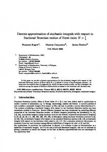
CENTAUR and TWOTRAN models, and shows the elongated nature of the quasirectangular cells in the CENTAUR grid. Five radial cells were used in each region, as were used in the TWOTRAN and ANISN models. For both TWOTRAN and CENTAUR, the quadrant was subdivided into 10 azimuthal zones; however, it should be noted that because of the azimuthal symmetry, only one azimuthal division was necessary for TWOTRAN. Total absorption rates, Pa, computed for each region type are in good agreement, although in the fuel regions the difference between the CENTAUR and TWOTRAN is approximately twice that between TWOTRAN and ANISN. A plot of the fluxes calculated by ali three methods for each energy group are shown in Figures 23 and 24. These figures demonstrate that the CENTAUR solution is in good agreement overall with the results of the other two codes, and show the strong radial variation in the scalar flux. In the group 1 (fast) solution, the three solutions are in good agreement for small radii; however, as the radius increases, the deviation of the CENTAUR solution from the other two solutions increases. This would tend to support the earlier proposition that the accuracy of the CENTAUR solution is limited by long, thin cells, since the length to width ratio increases as the radius gets larger. In further numerical experiments, as the number of azimuthal ceUs in the CENTAU R model was increased, the multiplication factor moved toward the value of ~1.305 predicted by the finite difference based codes. For an arrangement using 10, 20, and 40 azimuthal
(_)
(b) l:igur= 22. CENTAUR
(a)andTWOTKAN
(b)Compumt_onaJGri&_Used inCase4.
--B g i m m
II xim +m _'I
rqrmw
romp ,,, ,ur.....
lql......
" II r,. ....
,l,_i,
_
' ul' r" IF_ll'nq 'l'l_l '_lI
llr
72
0.48 -_
•_
0.46 0.44
1
0.42 "_ o
0.4
- . - ANISN .... .A.... TWOTRAN
0.38-
{
0
0.5
I I
I I
I i
1 1.5 2 Distance from Center (cm)
I
i
I
2.5
3
Figure 23. Fast Group Scalar Fluxes from Case 4.
0.42 -_,
0.41 - .
._ o'J r,O
0.390.4
- ANISN
•....a.... ---_--- TWOTRAN CENTAUR
(,_t_
0.38 ,_
0.37 0.36 -
r_
0.35 0.34 0
JI 0.5
)I 1 1.5 2 Distance from Center (cm)
iI 2.5
Figure 24. Thenrml Group Scalar Fluxes from Case 4.
1 I _F 1
{ 3
73
divisions for rings 1-3, 4-7, and 8-11 respectively, a multiplication factor of 1.30412 was computed. It was felt that perhaps the strong radial variation in the flux due to the structure of the problem might require further radial subdivisions to more accurately resolve the radial distribution.
Unfortunately, a finer radial grid would also require a finer azimuthal grid,
which would exceed the memory limitations of CENTAUR. Thus, freer cell structures were not studied. However, additional work with cylindrical geometries and simpler structures has indicated that accuracy is improved (in terms of agreement with ANISN and TWOTRAN) when cells are constructed of approximately equal-length sides. The cells are not required to have a square shape in order to obtain this improvement; triangles and pentagons do not appear to cause problems, as long as they are not severely distorted. While investigating the error described above, a second anomaly was discovered in the CENTAUR solution for this problem. It was found that the azimuthal flux profile, which should remain constant for this problem, actually had a significant variation with angle. The magnitude of the variation was found to decrease with increasing order of quadrature. Figure 25 illustrates the azimuthal variation of the flux in a fuel ring for this problem geometry. The amount of the deviation from the average value decreases with increasing order of quadrature, although the average remains approximately constant. The maximum deviation from average is as large as 1.40% for the $4 quadrature to 0.35% for S 16 quadrature.
In addition, the variation is symmetric about any multiple of 45°.
From the behavior shown in Figure 25 and from numerical experiments, the following observations were made. The behavior is a result of the combined effects of the shape and oriemation of computational cells and of the quadrature approximation of exact integration. It occurs when cells which are significantly larger in one dimension than in others are used, and is therefore related to the error described earlier in this section. It also results from the rotation of these cells; ff the orientation of the single long dimension is the same for ali ceils,, the phenomenon is not observed. Use of product-angular quadrature sets,42 in which the
i 4
|
74
azimuthal spacing of the component of each direction in the x-y plane is constant, 'also diminishes the effect. (Unfortunately, the overall accuracy of the solutions obtained using this type of quadrature is reduced.)
Figure 25, Azimuthal Variation in the Scalar Flux. d
The problem is due to a ray effect of a slightly different nature than that normally
|,t,
observed in discrete ordinates methods. The relative weight (expressed in texrns of
,,
relational coefficie_ats) of one side to an opposite side in a four sided polygon for the set of
d
characteristic directions varies according to the orientation of the polygon. As the polygon | i -7,-
75
becomes more square, the weight of one side relative to the opposite side becomes less direction dependent, and the orientation will have less effect on the solution. The more elongated a given dimension becomes, the more sensitive the solution becomes to the quadrature directions, requiring a higher order quadrature to diminish the effect. Both of the problems described in the previous paragraphs illustrate a weakness in the ESC method; however, the cause of these problems is related to the shape of the computational cell. While these limitations indicate that completely arbitrary and unconstrained cells structures can cause problems, this is a problem with ali discrete ordinates methods, and it appears that thexe remains considerable latitude in the shape and structure of a cell. Case 5: Application
in a Non.Orthogonal
Geometry
Case 5 was designed to show the adv,'mtage of the ESC approach over conventional approaches for a non-orthogonal geometry. For this case, an annular fuel rod was placed in an infinitely repeating hexagonal lattice, as shown in Figure 26. In this geometry, a rectangular region of symmetry can be,used to simplify the problem to one which could be reasonably approximated by TWOTRAN, as represented by the rectangular outline in Figure 26. The rectangular region is required so that TWOTRAN can apply reflective boundary conditions; a large number of small square cells were used to approximate the cylindrical regions of the fuel rod and enclosed moderator. The computational grid representing the rectangular region is shown in Figure 27. This model required a 30 by 52 cell computational grid using 0.1 by 0.1 cm cells, for a total of 1560 cells, and provides only a coarse approximation of the rounded surfaces of the annulus. The CENTAUR model for the same region takes advantage of its flexible cell structure to give a much closer approximation to the curved surfaces, as :;hown in Figure 28. In additio_r, this model used only 564 cotnputational cells, of various sizes and shapes.
_gll -m
_m
_m
_£_nm -------111 lli
19P"r,
lip,"
IFpnq r Iqq , _ ,_,li p,qfill ........
n,,, ......
,
....
rn,nnl ' 'll,r' q""
_'l_nql, _nl"
'nI1' ' Ilr'u'",iql"'
,rllli,nlplm ,ll'r' inlgnn, nq,llll"pi,,q'rqnn_lqlrl IMli_lgrfll, 'ra"
76
[_
Fuel
_
Moderator
Figure 26. Non-Orthogonal Hexagonal Geo_netry Used in Case 5. The problem geometry was intentionally formulated such that it could be approximated by a fmc rectangular mesh. Additional thae structure, such as flain cladding around the fuel material, would be difficult to model using TWOTRAN without increasing the number of cells by at least an order of magnitude, while the CENTAUR model could easily accommodate such features with little additional overhead.
77
Figure 27. Computational Grid Used by TWOTRAN in the Case 5 Geometry.
78
Figure 28. Com:_utational Grid Us_ by CENTAUR in the Case 5 Geometry.
!!
awp, , p,p,1,-,,tr"
,',p
, , ,t,,,_,,,, ,,ii_,,,,
,,
,,,,,,,
r,,,r,,,_ir,1,, ,,, ,,
nq,rl_rp ,, ,rllr,iwl
,_l_,r,_Ir lIT
I
I
I
li
_
i_,, ,, ,,, _,i ,,_"
,,_l,1'MtIl",qq_''
_tl'_pl'r,
', qwpt,r',
79
The geometry of Figure 26 is de,_a'ibed by an annular fuel rod of inner diameter 1.4 cm, outer diameter 4.6112 eta, and a center to center pitch of 6.0 cna between fuel rods. Because of the crude approximation resulting from the use of square cells to represent curved surfaces in the TWOTRAN model, it was not possible to match both volumes and surface areas for each region. Thus, it was decided to match the actual volume of the fuel region rather than the surface area of the region. Even with CENTAUR, while it was possible to more closely approximate the surface area of a fuel rod, there was a difference between the actual surface area and the area used in the model. Table 7 shows the volume and surface area of a fuel rod for both the CENTAUR and TWOTRAN models relative to I
the exact values. The values in brackets give the error in each approximation relative to the exact dimensions.
Because the total volume of fuel plus moderator is fixed by the
boundaries, matching fuel volumes in each model with the exact volume will also result in exact moderator volumes. However, no attempt was made force the volumes for each moderator region to be constant.
i
.....
__
I
lbl
......
i
Actual i
iiii
Volume
H II
15.1607
(crn3/unit depth) Inner Surface Area
4.3982
(cm2/unit depth) Outer Surface Area (cm2/unit depth) ....
14.4865
i
irlll
i
CENTAUR
till I
i
TWOTRAN ijL
iiiiIIl
i! !
ii I
i i
15.1607
15.16
[0.0% ]
[-0.005 %]
4.3856
5.6
[-0.29%]
[27%]
14.4410
18.4
[-0.3!%]
[27%] ....
Table 7. Ft_,elVolume and Surface Areas in CENTAUR and TWOTRAN Models
It is worth noting that the CENTAUR model could have been based on a single hexagonal cell, as shown by the hexagonal outline in Figure 26. Instead of reflective
-I
1 _J
,I,!
80
boundary conditions, l_riodic boundary conditions could be applied for opposing sides. As with traditional discrete ordinates codes, reflection in CENTAUR is limited to surfaces with horizontal or vertical orientations, because of the _2 rotational symmetry of tile quadrature set used. Thus, while reflection could have been used along the two vertical sides of the hex, it could not be used along the hex's other four sides. However, if a quadrature set with rc/3 rotational symmetry were used, reflective boundary conditons could be used on ali sides. li
Using the material properties from Case 4, given in Table 5, the problem was solved as
I
a two-group criticality problem. Agreement between the multiplication factors was found to
|
be much closer than had been expected, based on the Case 4 results. The multiplication factor and the group absorption probabilities computed by each code are given in Table 8.
!
lllill
.....
lln
_
__
,
IIIII _ __
,,,TWO_
k** Pa (fuel + moderator), g--.1 (fuel + moderato_r), g=2 i
,,
1.25557 0.420 _
0.580
....
_
.....
CENTAUR
: % Difference.
1.25551 0.419
-0.0047 -0.24
0.581
.....
0.17
Table 8. Calculated Values of k**and Pa for Case 5.
I q
Excellent agreement is seen between the two codes. The scalar flux distributions were also fotmd to be in close agreement, as shown in Figure 29. This plot depicts the flux
q_.l !
profile moving horizontally from the center of the moderator region locatexi inside a fuel
q_
-------
|
iii
element to the centerline of the moderator space between two fuel elements, i.e., along the bottom boundary of the rectangular region. Note that in Figure 28 the shape of the computational cells, although more rectangular than square, are not as severely distorted as the outermost cells in the previous test case.
qi
-li
_! qI q q
The close agreement with the multiplication factor computed by TWOTRAN would indicate
81
that either this amount of distortion has very little effect on the accuracy of the solution, or that both the TWOTRAN and CENTAUR solutions arc in error to approximately the same degree. The latter is unlikely, however, unless the agreement in results is very coincidental. Additionally, the radial variation of the flux, as evidenced in Figure 29, is not as severe as in the previous case. It might be argued that if the crude TWOTRAN model is capable of such accuracy, then there is no clear advantage in using the ESC method in non-orthogonal geometries. While this is true for this particular example, it should be realiz.exlthat this problem was selected such that a TWOTRAN solution could be obtained. As discussed earlier, additional details such as cladding would make the TWOTRAN model significantly more complicated. In addition, if the hexagonal lattice shown in Figure 26 had consisted of a safety rod dement surrounded by six dissimilar fuel elements, the problem would have strained the capabilities of TWOTRAN and other finite-difference based codes to a much higher degree. The five cases which have been presented in this chapter represent only a fraction of the cases which have been run to test CENTAUR.
These cases where chosen for discussion
here because they were particularly effective in highlighting the advantages and limitations of the ESC method in modelling various geometrical configurations.
Hopefully, these
examples have served not only to demonstrate the accuracy of the CENTAUR code, but also to highlight the advantages of the ESC approach.
82
t
1
J t t
'
oo,°_
i _ .
,
,._
=
CENTAUR Fast Group
i
TWOTRAN Thermal Group
_
CENTAUR Thermal Group ,
! ,!
--*--
,
,
L__
TWOTRAN Fast Group
i
I
°
,
!
0.15
l
t
.
I
t
t
i1 i
,i *
i
t !
i
1
_
'
!
!
' :
!
_
1
3
!
t
i
i i
0.1 i
i i
i
i ,
i
! 1
! t
i ,
t
:
0
0.5
1
1.5
2
2.5
3
•
:
!
|
i
j
i
_
i
t
_t
: I
Horizontal Distance from Center of Fuel Rod
|
!
|
] !
!
i | ! I J
!
i
I
i
d i
I
Figure 29. Fast and Thermal Fluxes from the Results of Case 5 Calculations.
83 CHAPTER VI CONCLUSIONS This dissertation has demonstrated the theory and application of the Extended Step Characteristic method, an extension of Lathrop's Step Characteristic method to irregularly shaped polygons. This method was incorporated into the CENTAUR computer program, and was validated with comparisons to the analytical solution for a simple cylinder and the numerical results of other, finite difference based discrete ordinates programs. These results demonstrated that the ESC method is in good agreement with existing discrete ordinates methods, and has the capability to use irregular cell structures in order to approximate the general shapes of arbitrary problem areas. This chapter will discuss some of the features and limitations of the method, and will explore some of the potential avenues for future work in both the theoretical and applied numerical aspects of the method. i
Strengths
and Weaknesses
of the Extended
Step Characteristic
Method
The CENTAUR code has been developed as a proof-of-principle tool for demonstrating the feasibility of the ESC method when translated into a numerical model. As such, it has not been designed to compete directly with existing discrete ordinates codes, and does not contain ali of the features or capabilities of other production class programs. However, in order to solve general problems, it has been written as a versatile tool capable of analyzing multiregion, multigroup problems with a diverse set of boundary conditions.
The five cases
presented in the previous chapter utilize many of features of the CENTAUR program, and served to validate both CENTAUR and the theory developed in the derivation of the Extended Step Characteristic method. The following paragraphs will summarize the important features of each case, based on the results and discussions of Chapter V. The fkrst case demonstrated that CENTAUR (and therefore the ESC method) is in good agreement with the finite difference results from TWOTRAN and ANISN for onedimensional slab geometry. However, this is to be expected; the step characteristic equation
!
-Iu !i
-II !1
84
(Equation 6) can be shown toreduce to a forward (or step) differenced finite difference approximation as the distance s becomes small. The ESC method is not as efficient as a f'mitedifference method in this geometry;however, this is not the intended use of the method. It was recognized from the beginning that the ESC method would not be competitive with existing methods when applied to problems easily described with orthogonal coordinates. However, problems with orthogonal geometries provide the opportunity to benchmark CENTAUR results against existing methods. The second case demonstrated similaragreement for a slightly more complicated twodimensional problem. It also demonstratedthat the ESC approach is subject to a slightly larger error than that of the diamond-differencedapproachin TWOTRAN, as evidenced by reduced ray effects due to numeric',ddiffusion. This result was expected, since in the rectangular geometryof this case, the ESC approximation reducesto the simpler Step Characteristic approach;SC is known to have a slightly higher error component than DD tor a given rectangular grid. The larger error is also expected to be present in non-rectangular geometries. The thirdcase studied actuallyrepresents the first test of a non-orthogonal geometry for CENTAUR. Althoughthe cylindrical geometry of this case can bemodelled exactly using the form of the transport equation developed for cylindricalcoordinates, it is only an approximation for CENTAUR. The ESC method is based on the characteristic form of the transport equation applied to straight-sidedcells in an x-y specified geometry; thus the representation of the curved surfaces of a cylinder is one of the many "non-orthogonal" geometries for which the method was developed. Results showed not only a good |
agreement to the analytical solution for various material properties, but also better agreement to the exact resultsthan could be obtainedby the TWOTRAN code.
i |
| ! |
The complexity of the geometryused in Case 4 served to demonstrate a weakness of the ESC method. For this case, CENTAUR was unable to match ANISN and TWOTRAN
am
| I
| III
| _11
_/1111,, _;,,l_lll,ir,ll_,.... ii_l,ll,_l
85
solutions for the same geometryas closely as in other tests. The differences were relatively small, but were most pronounced in the calculation of the multiplication factor for the problem. It was postulated that the error result_ a reduced order of accuracy due to the fact that computational cells were significantly elongated in a specific dimension relative to other dimensions.
Although other numerical experiments seem to confirm this hypothesis, it has
not been rigorously verified, ttowever, such behavior would be consistent with the kr,.own behavior of the Step Characterist:ic method applied in rectanga_lar geometries. In addition, it appeared that the solution aiso suffered from insufficient radial discretiztion due to a rapidly changing ladial scalar flux profile. Limitations in the ability of CENTAUR to handle significantly smaller mesh sizes due to memory constraints precluded further study of this problem. (Memory constraints resulted from hardware limitations in the IBM RS/6000 workstation used tn these analyses, and t_otfrom any theoretical limitation.) A second problem, also related to the elongated cells, was identified as a ray effect resulting from _he use of discrete directions to represent the angular distribution. This effect resulted from the fact that the maior axis of the elongated cells was rotated relative to the set of fixed characteristic directions for various cells used to represent the geometry. Nevertheless, even with some inaccuracy, CENTAUR has demonstrated its applicability in what is again a non-orthogonal geometry for the method. This geometry would have been extremely difficult to model using using a finite difference approach with rectangular cells in Cartesian coordinates, because of the large number of cells which would be required. The final case presented tl_eresults of a truly non-orthogonal geometry. The geome_, was simplified in order to accommodate a TWOTRAN solution with a reasonable mesh size, since a solution for a more complicated geometry would be of tittle value without a parallel calculation to which it could be compared. Results were found to be in very good agreement, much more than was expected due to the coarseness of the TWOTRAN approximation.
The CENTAUR solution required approximately one-third of the total
86
number of ceUs required by TWOTRAN, and still gave a closer approximation to the actual problem geometry. Additional details, such as cladding, gaps, or ribs, could have been easily introduced into the CENTAUR model, while such details would require an enormous increase in the number of ceils nee,de.xiin the TWOTRAN model. With the exception of the Monte Carlo solution of Case 2, numerical comparisons made in ali cases were limited to ANISN and TWOTRAN calculations. However, these two computer codes can be considered representative of practic_y
ali production class finite
difference discrete ordinates codes relative to the limitations of cell structta'e.s. Although both finite difference and finite element methods based on other cell shapes have been derived, these have been principally limited to simple three an6 tbur sided cells, and have not exhibited the generality found in the ESC approach. Thus, the Extended Step Characteristic method has added more generality to the theory of discrete ordinates. Limitations
Within
CENTAUR
While the preceding chapter demonstrated the applicability of the ESC method in gener, dized geometries, as weU as some of the apparent limitations in the method's accuracy, litge was said of the limitations inherent in CENTAUR itself. The purpose of this work was to provide the development of the theory and application, of the Extended Step Characteristic approach; CENTAUR was merely a tool used to apply the method. Thus, the practical limitations of CENTAUR itself have not been addressed in detail. However, it is worth noting at this point that substantial lirnitations exist in the current form of CENTAUR. Some of these problems were anticipated prior to beginning the code development, but were not considered to be,a detriment for the purposes of this research. Others were discovered as the development proceeded, and were addressed to the extent r_ecessary to complete this work. The primary limitation in CENTAUR is the time required to compute large, detailed problems. As mentioned earlier, most of the development and testing of the code was
87
performed on an IBM RS/6000 class workstation. Because of the rapid scalar processing capabilities of this tin,chine, the largest problems could be completed in less than an hour. However, similar ANISN and TWOTRAN calculations would complete in only a few minutes. The time required for CENTAUR to set up internal data stn2ctures and relational coefficients for a given geometry was small, less than approximately 5% of the total execution time; the bulk of the time was spent in the iteration pre>tess. Two factors contribute to CENTAUR's sluggish calculadonal cadence during the iteration process. First, the data structures used to store cell data were not optimally designed in terms of the computational algorithm when the code was developed.
Thus,
much indirect memory access and logical testing is performed during a calculation, reducing the program's computational efficiency. This problem could be 'addressed in a rewrite of key subroutines to take advantage of the now much better defined computational logic. However, the key factor which impedes the speed of a calculation is disk I/O, due to the large amount of data saved as relational coefficients. Since each set of coefficients is written to disk for each energy gToup in a multigroup problem, the same data must be read back in once every outer iteration. Even though the data is w_itten in binary format, the sheer size of each f'de can take 10-30 seconds to read for each energy group in each iteration. Because CENTAUR currently uses no acceleration techniques, several outer iterations are necessary for problems with fission or upscattering. Thus, CENTAUR can become I/O bound. This overhead time could be reduced by the use of high speed hardware such as solid suite disks; however, a more practical solution would be to reduce the amount of storage requin;d, to reduce or eliminate disk access time. Because of the nature of CENTAUR input, based on a line segment by line segment description of the problem geometry, it is generally very. cumbersome to assemble any but the simplest of problems "by hand.." Thus, for most of the problems analyzed, and for ali of the cases discussed in the previous chapter, it was necessary to write a specialized
I
r-
88
program to create an input deck for each new geometry type. Such codes were written with as much generality as possible, so that it was possible to change radial and azimuthal grids and material properties with little effort. However, in the development of such codes, it was difficult to determine if the candidate CENTAUR decks correctly represented the desired geometry. Thus, as a companion to the input processing codes, a graphical preprocessor named CENTART was written to read a CENTAUR input deck and provide a "plot" of the geometry represented by the input. The program, w_tten in C and using the windowing and graphics capability of the Macintosh II class personal computer, is independent of the problem geometry, and can scale and plot any valid CENTAUR input file. The output can be transfelred to other Macintosh applications via cut and paste operations. (Figures 20, 22, and 27 were created using CENTART. Only Figure 27 was modified, to include regional shading.) CENTART was found to be an invaluable debugging tool for the development of CENTAUR input. Similar in nature to the complexity of the input is the means by which to understand the code output. In its current form, CENTAUR is capable of providing in its output various properties (average fluxes and reaction rates for primary reaction types) on both a cell by cell and a zone basis, where a zone is defined in the input as a specific set of cells. For most applieations, this is sufficient. However, when trying to identify trends or anomalies in a solution, especially when debugging mainput deck, it is often, useful to look at various spatial! profiles. Because of the arbitrary nature of the cells in a CENTAUR model, it is often difficult to present such distributions in a meaningful way. A recent addition to the CENTAUR package is a post-processing code named LEONARDO, which uses geometrical information and fluxes provided in an output file at job completion to provide a color contour plot of two-dimensional flux distributions for each energy group. The magnitude of the flux in each cell is represented by a color selected from a color range scaled to the range of the flux values. This approach is similar to methods used in many other analysis
89
packages, especially in f'mite element codes. While such a plotting capability does not pro,,dde numerical values, it does provide insight into the behavior of the neutron population for any given geometry and set of boundary conditions, and can bt used to identify mist',xkes in input specifications. LEONARDO led to the discovery of the rotated cell ray effect described in the previous chapter, Possibilities
for Future
Development
Considerable potential exists for future development and enhancement of both the CENTAUR code and the ESC method itself. Beyond basic improvements in the code and pre- and post-processing capabilities alluded to in the previous section, potential exists for growth in the basic theory itself. However, certain key problems must first be addressed prior to moving fo_,,ard. The most significant problems facing CENTAUR axe memory utilization and speed. Many options exist for reducing the storage overb.ead; a prim_u'yconsideration would be to che_ckfor repeated relational coefficients. Because of the similarity of the shape of many cells with respect to a given characteristic direction and the rotational symmetry of the quadrature sets currently used, it is likely that the same relational coefficient, within a given level of tolerance, is repeated many times in Tnemory. Substantial memory savings could be obtained if repeated values were replaced with a single value _d a set of integer pointers. Also, although CENTAUR does not save zero terms, it does save terms which are very small but non-zero. It rr'.aybe possible to set these values to zero and save the memory space. However, this is unlikely to amount to a significant savings. The most benefit is likely to be seen by running the code on computers with large amounts of core memory. Traditionally, memory requirements of computer codes have pushed the limit of existing technology, providing the incentive for more and .more memory. Current trends indicate that large eanounts of core memory wiU be available on most systems in the very near fl_ture. Some of the options for increasing the speed of CENTAUR have been discussed
90
previously. However, the most significant gain in perfbrmance ntay be realized by taking advantage of the potential for paraUelization of the method. As was indicated earlier, the solution tbr each characteristic direction is independent of all other directions during the sweep process of each inner iteration; it is therefore possible to ,solveeach direction in parallel. This could result in a time savings factor on the order of the number of directions in the quadrature set (144 directions are used for a S 16quadrature set ). If a given parallel machine has available relatively large amounts of memory for each CPU, then angle dependent data can be saved with each direction on the CPU where it is needed; this would reduce the amount of storage required per CPU by the same quadrature-order dependent factor. Once memory and speed limitations have been overcome, the next logical step would be to extend the method to a three-dimensional representation.
The general theory remains
essentially the same, except that side-to-side relationships in two dimensions become faceto-face representations in the three-dimensional case, as polygons are extended to polyhedrons. This will provide the capability to perform deterministic calculations for complex and completely arbitrary volumes. A need for such capabilities has already been identified in the medical field, where boron-neutron capture therapy is used for the treatment of brain tumors, and a reasonable estimate of dose distributions inside the exposed individual's he'td is required. 43 An 'additional avenue for potential development is in elimination of the "step" approximation of constant source and boundary fluxes in each cell in favor of a linear approximation for these values. This would essentially be an extension of the Linear Characteristic method discussed in Chapter II. Since the LC approach has been shown to mitigate some of the problems inherent in the SC method, an derivation of an ESC-like approach based on the LC approximation would be likely to result in an improvement of the accuracy of the solution. However, as with the LC tnethod, such an Extended Linear
! I,
rR ....
_,
11_
Iii
.I
l,t
1_,
'111, .
,,lqlr,
,.
91
Characteristic approach would require additional computational overhead in terms of storage requirements and the number of operations performed per cell pcr iteration. Even in the current two dimensional ESC implementation, additional graphical preprocessing software is desirable. Custom programs used to generate input decks are useful when the geometry modelled is of a regular shape, even though it may be nonorthogonal. However, to be able to model completely arbitrary shapes, a tool which could enable a modeler to graphically position and define line segments or cells using a "click and drag" interface would be extremely useful. Such software exists in abundance, and would merely need to be tailored to the specific needs of CENTAUR. Another useful tool would be an "intelligent" preprocessor which could automatically fill a defined boundary with an optimum set of cells, and then reduce the information into the form accepted by CENTAUR. Moving into the domain of possible three-dimensional representations, one would need to construct versatile tools for both pre- and post-processing.
Much of this work has been
completed and has been successfully applied in three-dimensional finite element stnmtural analyses. Again, it would be necessary to tailor existing algorithms and packages to the specific needs of CENTAUR. The Extended Step Characteristic method has added a new dimension to discrete ordinates methods. With some additional development, CENTAUR could be put into use as a production code, modelling problems not easily undertaken using discrete ordinates methods. Such practical use will be necessary to more fully realize the advantages and limitations of the method, and would also help to def'me the user's needs in terms of working with the input and output of the code. It is expected that the ESC approach will provide significant contributions in both the nuclear reactor field for which it was originally conceived, and in non-reactor domains such as shielding and medical applications, where arbitrary shapes often need to be nxxtelled.
92 RE_ERENCES 1. G.I. Bell and S. Glasstone, Nuclear Reactor Theory, Van Nostrand Reinhold Company, New York (1970). 2. J.J. Duderstadt and L. J. Hamilton, Nuclear Reactor Analysis, John Wiley & Sons, New York (197 6). 3.
R. Sanchez and N. J. McCormick, Nucl. Sci. Eng., v 80, 481 (1982).
4. E.E. Lewis and W. F. Miller, Jro, Computational Methods of Neutron Transport, John Wiley & Sons, New York (1984). 5. A. Kavenoky, "Status of Integral Transport Theory," Prnc. Int Topl. Mtg. Advances in Mathematical Methods for the Solution of Nuclear Engineering Problems, Munich, Germany, April 27-29, 1981, European Nuclear Society (1981). 6. S. Nakamura, Computational Method_ in Engineering and Science, John Wiley & Sons, New York (1977). 7. W.H. Reed and T. R. Hill, "Triangular Mesh Methods for the Neutron Transport Equation," Proc. Conf. Mathematical Models and Computational Techniques for the Analysis of Nuclear Systems, Ann Arbor, Michigan, April 9-11, 1973, U. S. Atomic Energy Commission (1974). 8. W.F. Miller, EoE. Lewis, and E. (2. Rossow, "The Application of Phase-Space Finite Elements to the One-Dimensional Neutron Transport Equafion,"Nucl. Sci. Eng., v 51,145 (1973). 9. R.E. Alcouffe and E. W. Larsen, "A Review of Characteristic Methods Used to Solve the Linear Transport Equation," Proc. Inr Topl. Mrg. Advances in Mathematical Methods for the Solution of Nuclear Engineering Problems, Munich, Germany, April 27-29, 1981, American Nuclear Society (1981). 10. F. B. Hildebrand, Advanced Calculus for Applications, Prentice-Hall, Inc., New Jersey (1976). 11. K.D. Lathrop, "Spatial Differencing of the Transport Equation: Positivity vs. Accuracy," J. Comput. Phys., v 4, 475 (1969). 12. R. E. Alcouffe, E. W. Larsen, W. F. Miller, and B. R. Wienke, Nucl. Sci. Eng., v 71, !I 1 (1979). 13. E. W. "Larsen and R. E. Alcouffe, "The Linear Characteristic Method for Spatially Discretizing the Discrete Ordinates Equations m (x,y)-Geometry," Prnc. lnt Tnpl. Mtg. Advances in Mathematical Methods for the Solution of Nuclear Engineering Prnble_v, Munich, Germany, April 27-29, 1981, American Nuclear Society (1981). 14. K.D. Lathrop, "Spatial Differencing of the Two-Dimensional Transport Equation," ReporL GA-8746, Gulf General Atomic (1968). 15. V. S. Vladimirov, "Mathematical Problems in the One-Velocity Theory of Particle Transport," Atornie Energy of Canada Ltd., Ontm'io, 1963; translated from Trans V. A.
-l
.....................
' .....
HII
....
_
I '_r_
'iri.... q,, _= ......r,.......II]f"' 'IIi ............
lilt..... ,llr,'m'r,'_'rm' ..... llllllll_ ........lm, 'lP'll_!ll_lli(icr '_'1,
93 Steklov Mathematical Institute, v 61 (1961). 16. W. F. Miller, E. E. Lewis, and E. C. Rossow, "The Application of Phase-Space Finite Elements to the Two-Dimensional Neutron Transport F_.quationin X-Y Geometry,"Nucl. Sci. Eng., v 52, 12 (1973). 17. E. E. Lewis, W. F. Miller, and T. P. He1Lry,"A Two-Dimensional Finite Element Method for Integral Transport Calculations, Nucl. Sci. Eng., v 58, 203 (1975). 18. R. A. Lille and J. C. Robinson, "A Linear Triangle Finite Element Formulation for Multigroup Neutron Transport Analysis with Anisotropic Scattering," Report ORNL/FM5281, Oak Ridge National Laboratory (1976). 19. W. H. Reed, T. R. Hill, F. W. Brinldey, and K. D. Lathrop, "TRIPLET: A TwoDimensional, Multigroup, Triangular Mesh, Planar Geometry, Explicit Transport Code," Report LA-5428-MS, Los Alamos National Laboratory (1973). 20. T. J. Seed, W. F. Miller, and F. W. Brinkley, "TRIDENT: A Two-Dimensional, Multigroup, Triangular Mesh, Discrete Ordinates, Explicit Neutron Transport Code," Report LA-6735-M, Los Alamos National Laboratory (1977). 21. M. Mordant, "Some Efficient Lagrangian Mesh Finite Elements Encoded in ZEPHYR for Two-Dimensional Transport Calculations," Ann. Nucl. Energy, v8, 657 (1981). 22. G. Samba, "Discontinuous Finite Element Method for Solving the Two-Dimensional Neutron Transport Equation on Lagrangian Meshes," Nucl. Sci. Eng., v 92, 197 (1986). 23. J. E. Morel and E. W. Larsen, "A Multiple Balance Approach for Differencing the Sn Equations," Nucl. Sci. Eng., v 105, 1 (1990). 24. M. L. Adams, "A New Transport Discrefization Scheme for Arbitrary Spatial Meshes in X-Y Geometry," Prnc. Int. Topl. Mtg. Advances in Mathemetics, Computations, and Reactor Physics, Pittsburg, Pennsylvania, April 28-May 2 (1991). 25. R. E. Alcouffe, "A Diffusion-Accelerated Sn Transport Method for Radiation Transport on a General Quadrilateral Mesh," Nucl. Sci. Eng., v 105, 191 (1990). 26. R. Do O'DeU and R. E. Alcouffe, "Transport Calculations for Nuclear Analysis: Theory and Guidelines for Effictive Use of Transport Codes," Report LA-10983-MS, Los Alamos National Laboratory (1987). 27. K. Takeuchi, "A Numerical Method for Solving the Neutron Transport Equation in Finite Cylindrical Geometry," J. Nucl. Sci. Tech., v 6, 466 (1969). 28. K. Takeuchi, "Numerical Solution to Space-Angle Energy-Dependent Neutron Integral Transport Equation," J. Nucl. Sci. Tech., v 8, 141 (1971). 29. K. Takeuehi and N. Sasamoto, "Direct Integration Method for Solving the Multigroup Neutron Transport Equation in Three-Dimensional Geometry," Nucl. Sci. Eng., v 80, 536 (1982). 30. E. W. l.arsen and W. F. Miller, "Convergence Rates of Spatial Difference Equations for the Discrete-Ordinates Neutron Tran:pa_ Equations in Slab Geometry," Nucl. Sci.
94 Eng., v 73, 76 (1980). 31. D. V. Oopinath, A. Natarajan, and V. Sundararaman, Nucl. Sci. Eng., v 75, 181 (1980). 32. M.R. Wagner, D. A. Sargis, and S. C. Cohen, "A Numerical Method for the Solution of Three-Dimensional Neutron-Transport Problems," Ni,_cl.Sci. Eng., v 41, 14 (1970). 3 3. J. R. Askew, "A Characteristics Formulation of the Neutron Transport Equation in Complicated Geometries," Report AEEW-M 1108, United Kingdom Atomic Energy Authority (1972). 34. M. J. Halsull, "CACTUS - a Characteristic Solution to the Neutron Transport Equation in Complicated Geometries," Report AEEW-R 1291, United Kingdom Atomic Energy Authority (1980). 35. W. L. Filippone, "Particle Transport Calculations with the Method of Streaming Rays," Nucl. Sci. Eng., v 77, 119 (1981). 36. B.G. Carlson, "Transport Theory: Discrete Ordinates Quadrature Over the Unit Sphere," Report LA-4554, Los Alamos Scientific Laboratory (1970). 37. K. D. Lathrop and B. G. Carlson, "Discrete Ordinates Angular Quadrature of the Nuetron Transport Equation," Report LA-3186, Los Alamos Scientific Laboratory (1965). 38. C.E. Lee, "Discrete SN Approximation to Transport Theory," Report LA-2595-MS, Los Alamos Scientific Laboratory (1962). 39. K.D. Lathrop and F. W. Brinkley, Jr., "TWOTRAN-II: An Interfaced, Exportable Version of the TWOTRAN Code for Two-Dimensional Transport," Report LA-4848-MS, Los Alamos Scientific Laboratory (1973). 40. W. W. Engle, Jr., "A Users Manual for ANISN: A One Dimensional Discrete Ordinates Transport Code with Anisotropie Scattering," Report K-1693, Oak Ridge National Laboratory (1973). 41. K. M. Case, F. de Hoffman, and G. P. Placzek, "Introduction to the Theory of Neutron Diffusion," U.S. Government Printing Office, Washington, D. C. (1953) 42. I. K. Abu-Shumays, "Compatible Product Angular Quadrature for Neutron Transport in X-Y Geometry" Nucl. Sci. Eng., v 64, 299 (1977). 43. D. W. Nigg, et al, "Radiation Physics Aspects of Boron Neutron Capture Therapy," Prec. Topl. Mrg. New Horizons in Radiation Protection and Shielding, Pasco, Washington, April 26 - May 1, American Nuclear Society (1992).
95
VTTA The author, Mark David DeHart, w a s ^ ||||||||||||||||||||||||||||^ |||||^ ^ h is
parents are Major (Ret.) Donald D.
DeHart and Judy M. DeHart, who reside in North Richland Hills, Texas. Mr. DeHart graduated from Edward W. Clark High School in Las Vegas, Nevada in June, 1978. After attending Iowa State University for a year, he left school to work for a year and a half. He transferred to Texas A&M University in January 1981. In May, 1984, he graduated Cum Laude with a Bachelor of Science degree in Nuclear Engineering. He began his graduate studies in June of the same year, and was appointed a Fellow within the Department of Energy’s Nuclear Engineering Fellowship Program at Texas A&M in September, 1984. He earned a Master’s degree in Nuclear Engineering in December 1986. He joined the staff of the University as a Lecturer in Septen