278
IEEE TRANSACTIONS ON EDUCATION, VOL. 49, NO. 2, MAY 2006
A Distance PLC Programming Course Employing a Remote Laboratory Based on a Flexible Manufacturing Cell Oriol Gomis Bellmunt, Student Member, IEEE, Daniel Montesinos Miracle, Student Member, IEEE, Samuel Galceran Arellano, Andreas Sumper, Student Member, IEEE, and Antoni Sudrià Andreu, Senior Member, IEEE
Abstract—The increasing necessity of engineers capable of handling the problems of the industry and able to face the technical challenges they will encounter in their professional career is boosting the teaching methods based on projects and real applications. The Center of Technological Innovation in Static Converters and Drives, Technical University of Catalonia (CITCEA-UPC) group, Barcelona, Spain, has introduced such learning methods applied to the automation field in a course taught for the electrical engineering degree and in some postgraduate workshops, making the laboratory platforms available through the Internet in order to allow the use of such practices in e-learning-based courses. The learning method is based on a flexible manufacturing cell, resulting from the collaboration between the CITCEA-UPC and Schneider Electric and its Training Center. The problem proposed to the students is the automation of such a cell with commercial programmable logic controllers (PLCs). The experience has proved to be positive, and the students have valued it accordingly. Index Terms—Flexible manufacturing cell, manufacturing automation, programmable logic controllers (PLCs) programming, project-based learning, remote laboratory.
I. INTRODUCTION
T
HE overwhelming developments of the Internet technologies are becoming enabling agents of new teaching methods. Among them, the remote laboratories are increasingly being considered as a serious alternative to the classical local laboratories; therefore, they are being used by many institutions worldwide. In [1], the remote control of a robot is described. The control is implemented over the Internet using a client–server architecture with User Datagram Protocol/Internet Protocol (UDP/IP). In [2], a remotely operated experiment to determine the value of the speed of light is presented. To undertake such a calculation, the resonant behavior of a reactive inductance–capacitor (LC) circuit is used. In [3], a remote laboratory for automatic control is presented. The students interact with the physical systems through the Internet. The processes available are a dc motor, a water tank, a magnetic levitation system, a two-degrees-of-freedom (2-DOF) Manuscript received July 28, 2005; revised January 22, 2006. The authors acknowledge the support received from Schneider Electric Spain and its Training Center. The authors are with the Center of Technological Innovation in Static Converters and Drives (CITCEA), Electrical Engineering Department, Technical University of Catalonia, 08028 Barcelona, Spain (e-mail:
[email protected]). Digital Object Identifier 10.1109/TE.2006.873982
helicopter simulator, and a LEGO mobile robot. In [4], a Web-based programmable logic controller (PLC) laboratory for manufacturing engineering is presented. Two computers are used: one working as a system supporter and the other as a system controller. In [5], a large-scale, Web-based, virtual oscilloscope laboratory is presented, introducing an experiment using real-time video. In [6], a remote laboratory with a laser and a galvanometer scanner controlled by an embedded system are shown. In [7], different experiences of remote laboratories are explained, including an instrumented domestic electric iron (thermodynamics, mechatronics, and control), a sand weighing machine (bulk materials handling and PLCs), a position control (classical control systems), a torsional vibration system (dynamics and vibration control), and a telerobot (robot kinematics and control). In [8], the MARVEL project is introduced, including online laboratories in solar energy, robotics, and electropneumatics, while providing examples of fully remote experimentation settings available via the Internet and also providing mixed-reality environments, where real devices interact with simulation models. In [9], a remote workbench based on a Web server is presented with a set of controlled instruments and several circuits, sensors, and actuators. The control and the user interface software is developed using LabView and Pearl routines ensuring access control and system protection. In [10], another platform to create a remote laboratory applied to a vertical store is presented. Regarding general analysis of such teaching strategies, [11] presents a field study analysis comparing remote and local learning, concluding that the introduction of distance learning presents important advantages. In the Center of Technological Innovation in Static Converters and Drives, Technical University of Catalonia (CITCEA-UPC), Barcelona, Spain, a remote laboratory experience with a flexible manufacturing cell (Fig. 1) has been performed with the collaboration of Schneider Electric and its Training Center. The flexible cell is a small-scale industrial system in which the students can learn and become familiar with real industrial components, such as position sensors, pneumatic and electrical actuators, drives, PLCs, and industrial communication networks. Such skills can be better acquired allowing the students to connect directly to all the devices by means of Ethernet cards, with no need for computers working as servers [1], [4]–[6], [9]. Hence, no differences in the connection, programming, and debugging procedures exist between
0018-9359/$20.00 © 2006 IEEE
GOMIS BELLMUNT et al.: A DISTANCE PLC PROGRAMMING COURSE EMPLOYING A REMOTE LAB
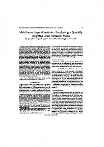
Fig. 1.
279
Flexible manufacturing cell.
Fig. 2. Scheme of the cell and the communication network.
the local and the remote students, since all of them connect to the same Ethernet card of the PLC. The remote laboratory is used in the course Electrical Workshop of Automation. Such a course is part of the Electrical Engineering degree and is optional in the student curriculum. The paper is structured as follows. In Section I, the remote laboratory is introduced. The laboratory setup and all the components concerned are described in Section II. In Section III,
the course with its corresponding sessions is explained. The results are discussed in Section IV, and finally, the conclusions are summarized in Section V. II. LABORATORY SETUP A general scheme of the whole setup is shown in Fig. 2. One can see that no computer working as a server is needed. The
280
Fig. 3.
IEEE TRANSACTIONS ON EDUCATION, VOL. 49, NO. 2, MAY 2006
Stations of the flexible manufacturing cell. (a) Station 1; (b) station 2; (c) station 3; and (d) station 4.
users can connect directly to the PLCs or to the Internet protocol (IP) camera, with the corresponding simplicity and increased ease of maintenance. The system allows the connection of four different users connected simultaneously to the four different PLCs, all of them connected to the same IP camera. A. Flexible Manufacturing Cell The flexible manufacturing cell shown in Fig. 1 is the system to be controlled. It must manufacture different elements depending on the binary codification of the moving base elements. Each element contains at least one cylindrical container and one cover. Depending on the codification, it contains also a plate and a ball. The cell is composed of four different stations performing four different tasks. The different stations are physically interconnected by means of a conveyor belt, moved by an induction motor driven with a frequency converter, so that each base moves at the right speed following the sequence 1-2-3-4-1. In the first station [Fig. 3(a)], an empty container is placed in a moving base. In the second station [Fig. 3(b)], either a plate or a ball is placed depending on the codification. In the third station [Fig. 3(c)], the cover is placed, and finally, in the fourth station [Fig. 3(d)], the produced element is stored in the right position. To perform the different operations, pneumatic actuators, capacitive and inductive sensors, electric motors, and an encoder are employed. B. Control System The cell is controlled with programmable logic controllers (Modicon TSX Micro, supplied by Schneider Electric, Barcelona, Spain). Each station has its own PLC, which must
control the manufacturing sequence and communicate with the others. The PLCs have several input–output cards, including digital inputs and outputs, analog inputs and outputs, and counting modules. The students have to program the PLCs using some of the different languages defined in the IEC61131-3 standard [12] [Structured Text (ST), Instruction List (IL), Ladder Diagram (LD), Function Block Diagram (FBD), and Sequential Function Chart (SFC)]. Since they have to deal with a sequential process, they use SFC (GRAFCET) as the main language, and use the other languages as appropriate. The Guide d’Études des Modes de Marches et d’Arrêts (GEMMA, or run/stop modes guide) is also employed, but it is implemented using SFC. The software employed is PL7 Pro, commercialized by Schneider Electric. C. Communications Architecture The communication between different PLCs and between PLCs and computers is especially significative. An Ethernet card capable of supporting the Modbus and Unite over the Transmission Control Protocol/Internet Protocol (TCP/IP) protocols has been employed to allow such connectivity. Therefore, the PLCs employed are accessible through the Internet, either to be programmed using the software PL7 Pro or to allow the reading and writing of information by Supervisory Control and Data Acquisition (SCADA) systems. An IP camera (see Fig. 4) has been introduced to allow the students working remotely to watch the process in progress. The remote laboratory does not need a computer working as a server. The users can connect directly to the PLCs and program them. The PLCs also have a Web server, where the user can check statistics and general information about the controller.
GOMIS BELLMUNT et al.: A DISTANCE PLC PROGRAMMING COURSE EMPLOYING A REMOTE LAB
281
Fig. 4. IP camera website.
III. COURSE DESCRIPTION Although the course Electrical Workshop of Automation can be completed in any year, most of the students are in the third or fourth year of the degree. Students can choose to do either local or remote exercises. The present work focuses on the second option. In any case, the laboratory exercises are geared toward project-based learning; the practices are not considered as isolated problems to be solved, but as general projects to be developed. The theoretical background is given in a Moodle-based Website.1 This background includes the basics of electrical and pneumatic actuators, drives, position sensors, PLC programming (GRAFCET, GEMMA, ladder language, structured language, etc.), and communications between systems (Ethernet). After ensuring (by means of autoevaluation questionnaires) that they have the required background, the problems are presented, and the students need to develop remotely the control of one of the four different subcells. They will be moved through the different subcells in different exercises until they have finished all of them properly. The students receive the needed software with the corresponding instructions, and they install it in their computer. To supervise the evolution of the cell, they use an IP camera. Although the practical course is organized in eight sessions or exercises, only one general problem is to be solved by the students—the entire automation of the cell. This approach fits into project-based learning methods, where the students have to work with general projects instead of single sessions. After the eight sessions described between Section III-A and Section III-H, the students have to write a report in which the entire project is to be documented. 1http://moodle.org/
A. Session 1: LD Ladder Diagram In the first session, the students learn how to configure the PLC and its input–output modules properly. The students are required to develop simple programs using the ladder diagram language. They learn how to work with the different kinds of variables, inputs, and outputs of the controller. The different types of timers and counters are learned, and some easy exercises are completed using them. B. Session 2: SFC Sequential Function Chart The students learn how to program with SFC and how to structure a sequential program. They use SFC for very easy sequences, such as the cover placement in the moving base (station 3), but they grasp the way of coping with sequential processes. C. Session 3: ST Structured Text The difficulty of programming loops or complex equations is presented and the option of working with a structured text language is shown. The problem of storing the manufactured element in station 4 is stated in order to require the students to develop small programs using indexed variables, float numbers, and complex equations. D. Session 4: GRAFCET Implementation on Station 1 The students begin the automation of the cell. They already have been introduced to the software and the different languages so that they can face this automation problem. In station 1, the base is to be located in the moving base after ensuring that it has the right position (if it has the wrong position, it is rejected). The students are encouraged to work with GRAFCET; nonetheless, they can choose the language they use in every part of the program.
282
IEEE TRANSACTIONS ON EDUCATION, VOL. 49, NO. 2, MAY 2006
E. Session 5: GRAFCET Implementation on Station 2 The students continue with the automation of the second station, where either a plate or a ball is to be introduced in the base depending on the codification. They are encouraged to use the different languages learned so that they will discover the advantages and drawbacks of each of them.
TABLE I SURVEY AND EVALUATION DESCRIPTION
F. Session 6: GRAFCET Implementation on Station 3 The automation of the third station is undertaken. In such a station either a plastic or a metallic cover is to be placed over the base. The students are motivated to try to make the code clear and easy to understand. The documentation of the program and its variables are discussed and carried out using external software (Microsoft Excel). The students are motivated to do the shortest (in size) and the fastest (in execution time) possible program, thereby understanding the size and time limitations of the PLC. G. Session 7: GRAFCET Implementation on Station 4 The fourth station is automated, including the configuration and programming of the incremental encoder employed for the manufactured element storage. The concept of fast inputs and outputs must be understood by the students in order to make the encoder work properly. H. Session 8: GEMMA Implementation on a Chosen Station The students can choose one station to implement the GEMMA guide and to test how it works. In this the last exercise, they are encouraged to use all the skills they have acquired. The final program is not only expected to work, but also has to be compact, clear, robust, and optimum. I. Final Report The students prepare a final report to be submitted to the instructor. They have to include some of the programs they have carried out and some of their conclusions about the entire work. This very important step is the main source for the continuous evaluation assessment of the students. IV. RESULTS EVALUATION The platform has been tested by 25 volunteer students, divided into two different groups: the local group, composed of 14 students and the remote group, composed of 11 students. All the students had the same initial level, since none of them had ever attended a PLC programming course nor programmed a PLC. The students belonging to both groups have been able to implement the programs and make the cell work, but they achieved different complexity levels. Although the course has been valued in general terms very positively, three students enrolled in the remote group have pointed out that the major drawback is the necessity of a good Internet connection to watch the real-time IP camera at an acceptable rate. Two different assessments have been undertaken, resulting in continuous evaluation and final marks. The first one considers the work done during the whole course, mainly shown in the final report submitted to the instructors. The final mark is ob-
tained as the result of averaging the continuous evaluation and final examination marks. All the students, including those who have undertaken the local practices, have been requested to answer (with marks 1–5) an anonymous questionnaire and submit it to the instructors. The final report has been assessed according to the following criteria (each criterion one point). 1) The student has submitted the report and has undertaken it as described in the bases. 2) The documentation included in the program is clear and helps one understand and follow the program. 3) The cell works in the more favorable cases. 4) The student has delved into the GEMMA guide capabilities; hence, he or she considers some of the problems that appear when the operation mode (automatic/manual) is eventually changed. 5) The cell works in all the different scenarios described (emergency stops, sensors failure, etc.). In the final exam, the students have answered a test covering the contents studied in the course and have implemented a program similar to the practices carried out. They have been assessed according to the criteria described above. The survey questions and results and the marks obtained in the continuous and final evaluation are shown in Table I and II. Note that questions R1 and R2 have been answered only by the remote group. Graphical results can be seen in Fig. 5. The comparison of the results between the two groups show no significant differences, neither in the survey answers nor in the qualification marks. Questions Q1, Q2, and Q4 indicate more satisfaction in the local group, while in Q3, Q5, and Q6 the remote group values the course more positively. The remote group continuous evaluation mark is a bit higher, but the final mark is slightly better for the local group. Although some conclusions can be extracted from such results, the overall differences shown seem to follow the different student abilities more than the differences in the teaching methods employed. The authors believe that the drawbacks of distance learning (mainly, the partial perception of the laboratory, the technical requirements, and the more reduced communication between the students and with the instructor) are balanced with the advantages
GOMIS BELLMUNT et al.: A DISTANCE PLC PROGRAMMING COURSE EMPLOYING A REMOTE LAB
283
TABLE II SURVEY AND EVALUATION RESULTS
Fig. 5.
Results of the questionnaire and the continuous and final marks. (a) Result distribution. (b) Survey and evaluation results.
(extra motivation of the students and time and space laboratory constraints removal) so that the final outcome is not significantly different. Forthcoming improvements in information technologies can minimize the drawbacks of distance learning and boost it even further. V. CONCLUSION The present paper introduces a remote laboratory and an automation e-learning-based course to be used in the course Electrical Workshop of Automation. The laboratory setup and the course structure have been presented. The course teaches PLC
programming skills to the students and makes them acquire basic knowledge in the field, allowing them to work with some of the common situations of industry. As seen in the survey, the students have shown a good opinion about the course. Furthermore, the results obtained in the reports are also encouraging. Hence, one can conclude that the experience has been positive and is worth repeating in the following years. Regarding further improvements, the main challenge is the Internet connection dependence of the users. The lack of highspeed Internet creates a technological boundary. With the scope
284
IEEE TRANSACTIONS ON EDUCATION, VOL. 49, NO. 2, MAY 2006
of international cooperation with some developing countries, this issue is becoming very relevant, and some actions have been and are being taken. Among them the use of a Supervisory Control And Data Acquisition (SCADA) system, which does not need a large amount of data to transmit, is appearing as a reliable alternative.
REFERENCES [1] B. Aktan, C. Bohus, L. Crowl, and M. Shor, “Distance learning applied to control engineering laboratories,” IEEE Trans. Educ., vol. 39, no. 3, pp. 320–326, Aug. 1996. [2] C. Enloe, W. Pakula, G. Finney, and R. Haaland, “Teleoperation in the undergraduate physics laboratory—Teaching an old dog new tricks,” IEEE Trans. Educ., vol. 42, no. 3, pp. 174–179, Aug. 1999. [3] M. Casini, D. Prattichizzo, and A. Vicino, “The automatic control telelab,” IEEE Control Syst. Mag., vol. 24, no. 3, pp. 36–44, Jun. 2004. [4] C. Saygin and F. Kahraman, “A Web-based programmable logic controller laboratory for manufacturing engineering education,” Int. J. Adv. Manuf. Technol., vol. 24, pp. 590–598, 2004. [5] C. C. Ko, B. M. Chen, S. H. Chen, V. Ramakrishnan, R. Chen, S. Y. Hu, and Y. Zhuang, “A large-scale Web-based virtual oscilloscope laboratory experiment,” Eng. Sci. Educ. J., pp. 69–76, Apr. 2000. [6] N. Faltin, A. Böhne, J. Tuttas, and B. Wagner, “Distributed team learning in an Internet-assisted laboratory,” presented at the Int. Conf. Engineering Education, Manchester, U.K., Aug. 2002. [7] J. Trevelyan, “Lessons learned from 10 years experience with remote laboratories,” presented at the Int. Conf. Engineering Education Research Progress Through Partnership, Ostrava, Czech Republic, Jun. 27–30, 2004. [8] D. Müller and J. M. Ferreira. (2005) Online labs and the marvel experience. Int. J. Online Eng. [Online], vol (1). Available: http://www.marvel.uni-bremen.de/index.php?id=52 [9] D. Anton, R. Bragos, and P. J. Riu, “Remotely accessible laboratory for instrumentation and sensors,” in Proc. Instrumentation Measurement Technology Conf. (IMTC), Como, Italy, May 2004, pp. 1272–1276. [10] A. Leleve, P. Prevot, C. Subai, D. Noterman, and M. Guillemot, “Toward remote laboratory platforms,” presented at the 7th World Multiconf. Systemics, Cybernetics Informatics (SCI), Orlando, Fl, Jul. 2003. [11] J. Tuttas, K. Ruetters, and B. Wagner, “Telepresent vs. traditional learning environments—A field study,” presented at the Int. Conf. Engineering Education, Valencia, Spain, Jul. 2003. [12] IEC61131-3 Programmable Controllers—Part 3: Programming Languages, 2nd ed. Geneva, Switzerland: IEC International Electrotechnical Commission, 2003.
Oriol Gomis Bellmunt (S’05) was born in Alió, Tarragona, Spain, in 1976. He received the M.Sc. degree in electrical engineering from the School of Industrial Engineering of Barcelona (ETSEIB), Technical University of Catalonia (UPC), Barcelona, Spain, in 2001. He is currently working toward the Ph.D. degree at UPC. In 1999, he joined Engitrol, Barcelona, Spain, as a Project Engineer in the automation and control industry, implementing control and supervision systems in several cement, chemical, paper, and transportation industries. In 2003, he developed part of the Ph.D. dissertation in the DLR (German Aerospace Center), Braunschweig, Germany, supported by a Marie Curie Stipend grant by the European Community under the program Smart Lightweight Structures and Transportation Application. Since 2004, he has been an Associate Professor in the Electrical Engineering Department, UPC. He is also involved in the Center of Technological Innovation in Static Converters and Drives (CITCEA), UPC. His research interests include the fields linked with smart actuators, electric machines, industry automation, and engineering education.
Daniel Montesinos Miracle (S’01) was born in Barcelona, Spain, in 1975. He received the M.Sc. degree in electrical engineering from the School of Industrial Engineering of Barcelona (ETSEIB), Polytechnical University of Catalonia (UPC), Barcelona, Spain, in 2000. He is currently working toward the Ph.D. degree in the field of sensorless motor control at UPC. In 2001, he joined Salicrú Electronics, S.A., Santa Maria de Palautordera, Spain, as a Research and Development Engineer in the field of uninterruptible power supplies (UPSs). Since 2001, he has been involved in the Center of Technological Innovation in Static Converters and Drives (CITCEA), UPC, as a Research Collaborator. He carried out research projects in the field of motor control, static converters and drives, and industry automation. Since 2005, he has been an Associate Professor at the Electrical Engineering Department, UPC. His primary research interests are motor control and converters for power supplies and drives and engineering technology education. Mr. Montesinos Miracle has received a prize from the Spanish Association of Electrotechnics and Electronics (AEE) for his Final Master’s work in 2001.
Samuel Galceran Arellano was born in Lleida, Spain, in 1971. He received the M.Sc. degree in electrical engineering and the Ph.D. degree from the Technical University of Catalonia (UPC), Barcelona, Spain, in 1997 and 2002, respectively. In 1997, he joined the Electrical Engineering Department, UPC, as an Assistant Professor. He developed several projects for industry, and in 2001, he joined the Center of Technological Innovation in Static Converters and Drives (CITCEA), UPC, where he belongs to the CITCEA Directorate staff. His primary research interests are motor control and converters for power supplies and drives.
Andreas Sumper (S’05) was born in Villach, Austria, in 1973. He received the M.Sc. degree in electrical engineering from the Technical University of Graz, Austria, in 2000. He is currently working toward the Ph.D. degree at the Technical University of Catalonia (UPC), Barcelona, Spain. From 2000 to 2001, he was Project Manager in the automation industry. In 2002, he joined the Center of Technological Innovation in Static Converters and Drives (CITCEA), UPC, where he is in charge of research and innovation projects with the local industry in the field of electrical engineering. His research interests are power quality, power system studies, distributed generation, and engineering education.
Antoni Sudriá Andreu (M’95–SM’05) was born in Barcelona, Spain, in 1950. He received the M.Sc. degree in electric and electronics engineering and the Ph.D. degree from the Technical University of Catalonia (UPC), Barcelona, Spain, in 1979 and 2005, respectively. In 1979, he joined the Electronics Engineering Department, UPC, as an Assistant Professor, where he first developed his work in microprocessor applications and after in power electronics. He became a recognized expert in these two areas, and as a consequence, he managed a lot of industry research projects in the fields of switching power supplies, voltage regulators, high-voltage inverters for railway applications, and uninterruptible power supply (UPS) inverters. He taught several subjects covering power electronics, basic electronics, and microprocessors. In 1980, he joined the Research and Development Department of La Maquinista Terrestre y Marítima (MTM), currently Alstom, a very important railway Spanish manufacturer, where he developed static power converters for traction (trains) up to 1-MW vector controlled inverter and several high-voltage static converters for auxiliary services in traction. At the same time, he continued as a part-time Associate Professor in the Electric Engineering Department, UPC, where he became a full-time Associate Professor in 1985. The subjects he teaches focus on electrical machinery and their control, power electronics, industrial automation with programmable logic controllers (PLCs), and railway technologies. He is the author or coauthor of more than 100 publications, including several books in his fields of expertise, such as power electronics, power quality, digital motion control, and industrial automation. He manages a large quantity of industry research projects, and, therefore, in 2001, he founded, with a Government agreement, the Center of Technological Innovation in Static Converters and Drives (CITCEA), UPC (www.citcea.upc.edu), which has two areas of interest—electrical energy and mechatronics—and develops about 10–15 research projects in each area every year. One of CITCEA’s objectives is technology innovation transfer to the industry, and to achieve this goal, CITCEA offers more than 600 hours in courses attended by industry professionals and, for more than four years, the Mechatronics Master’s degree. Since 2001, he has been the Center Director of CITCEA, where he manages more than 30 highly qualified CITCEA engineers.