A Distributed Algorithm for Pattern Formation by Autonomous Robots, with No Agreement on Coordinate Compass Swapnil Ghike1 and K. Mukhopadhyaya2 1
Computer Science and Information Systems Group Birla Institute of Technology and Science, Pilani 333031, India 1
[email protected] 2 Advanced Computing and Microelectronics Unit Indian Statistical Institute, 203 B T Road, Kolkata 700108, India 2
[email protected] Abstract. The problem of coordinating a set of autonomous, mobile robots for cooperatively performing a task has been studied extensively over the past decade. These studies assume a set of autonomous, anonymous, oblivious robots. A task for such robots is to form an arbitrary pattern in the two dimensional plane. This task is fundamental in the sense that if the robots can form any pattern, they can agree on their respective roles in a subsequent, coordinated action. Such tasks that a system of robots can perform depend strongly on their common agreement about their environment. In this paper, we attempt to provide a distributed algorithm for pattern formation in the case of no agreement on coordinate axes. We also discuss the limitations of our algorithm. Key words: Autonomous robots, Pattern Formation, No Compass, Mobile Robots
1
Introduction
Systems of multiple autonomous mobile robots engaged in collective behaviour (also known as robot swarms) have been extensively studied throughout the past two decades. These robots have motorial abilities allowing them to move; they also have sensorial abilities implying that they can sense their environment. They are anonymous - not a single robot can be distinguished from others; cannot communicate explicitly - they have to observe positions of other robots and accordingly decide; they are oblivious - they cannot remember the past computations. Moreover, they perform in completely asynchronous fashion with respect to time lengths of computation cycles, which brings them closest to practical situations. Most studies assume these robots to be simple points for theoretical analysis. This subject is of interest for a variety of reasons. The main advantage of using multiple robot systems is the ability to accomplish tasks that are infeasible for a single robot, powerful as it may be. The use
2
Swapnil Ghike and K. Mukhopadhyaya
of simpler, expendable individual robots results in decreased costs, increased reusability, increased expandability and easy replacement. These systems have immediate applicability in a wide variety of tasks, such as military, search and rescue, mining operations and space missions. There are algorithms for arbitrary pattern formation problem in cases of partial or full agreement on coordinate compass. For the no agreement case, the known research goes only as far as saying that arbitrary pattern formation is not possible. In this paper we have tried to address this particular case by proposing a distributed algorithm which can form a large range of patterns even when there is no agreement on compass.
2
Related Work
There has been a lot of interest generated in the engineering area by the pioneering research activities which include the Swarm Intelligence of Beni et al. [5], Parker [6], Balch and Arkin [7], to cite just a few. There are researches related various other problems like gathering problem by Peleg et al [9], flocking by Prencipe [2]. Two main approaches are common for solving the problem of arbitrary pattern formation. The first approach was employed in the investigations of Suzuki and Yamashita [3] [4], and the second approach is by Prencipe et al. [2] which assumes complete asynchronicity in a single computation cycle. In both these approaches, a computational cycle is defined to consist of four phases: 1. Wait 2. Look 3. Compute 4. Move. The difference between the two approaches is that first approach assumes the computation cycle to be a single step, i.e., it consists of instantaneous actions. In second approach, complete asynchronicity in the cycle allows different phases of the cycle to be of arbitrarily different, but finite time lengths. We believe that complete asynchronicity in the cycle renders the model closer to practical situations. We assume that the robots have infinite visibility in the plane, i.e., their view of environment is not restricted by distance and they are dimensionless points. Thus we follow the CORDA (Coordination and control of a set of robots in a totally distributed and Asynchronous Environment) model of Prencipe, Flocchini et al [8], since we believe that complete asynchronicity allowed by this model is closer to practical situations. We also follow the definition of Arbitrary Pattern Pattern Formation Problem given by Prencipe et al. [8]. They have proved that arbitrary pattern formation is not possible in case of no agreement of coordinate compass. But there is a scope for forming patterns with the exception of only a few types, and this is exactly what we have tried to solve.
3
The Algorithm
Input: An arbitrary pattern P is described as ratios of sides and angles between the sides. There is no agreement on the coordinate system. An initial configuration of point robots in two dimensional plane is given.
Pattern Formation with No Agreement on Coordinate Compass
3
Assumptions: Unit distance is denoted by u, origin by O. EndC is an expression which means: If (destination Is Equal to the point where I currently stand) Then destination:= null; END OF COMPUTATION. Algorithm NoCompass C1,P1 := MinimumEnclosingCircle(InitialConfigurationRobots), Its centre; G := Complete Graph obtained by connecting every point of input pattern with every other point of input pattern; S := Smallest Segment in G out of all possible segments; |S|:= u; (5) Pattern := PlotLocalPattern(); /* Plots the pattern in local coordinate system of robot. Output is a pattern with segment S on local positive X-axis, with smallest of the segments in G adjoining S making acute angle with local positive Y-axis. Their intersection is at local origin.*/ C2, P2 := MinimumEnclosingCircle(Pattern), Its centre; (10) FinalPositions:=FindFinalPositions(C1,C2,P1,P2,Pattern); RO := Robot at origin; NR1 := Robot nearest to O on Positive X-axis at distance > 0; NF1 := Final position nearest to O on Positive X-axis at distance > 0; PPeriphery := Robots on periphery of C1; (15) FPeriphery := Final Positions on periphery of C1; Case I Am * RO: If P1 is in FinalPositions Then destination :=null; EndC. (20) Else destination := Point on Positive X-axis at distance ² >0 ; EndC. * NR1: If (P1 is Not in FinalPositions AND There Is a Robot at P1) Then destination :=null; EndC. Else (25) If (P1 is in FinalPositions AND There Is No Robot at P1) Then destination := P1; EndC. If (P1 is in FinalPositions AND There Is a Robot at P1)) Then If ((I am Not at NF1) AND (30) (∀ Only One Robot ri such that 0 < |O − ri | < (max|O − N R1|, |O − N F 1|+ ² ))
4
Swapnil Ghike and K. Mukhopadhyaya
Then destination := NF1; EndC. Else destination := null; EndC. * One of RPeriphery : If ((P1 is Not in FinalPositions AND There Is a Robot at P1) OR (35) (P1 is in FinalPositions AND There is No robot at P1) OR (∀ More than One Robot ri such that 0 < |O − ri | < (max|O − N R1|, |O − N F 1|+ ²) OR (NR1 Is Not at NF1) OR (∀ Pos In FPeriphery such that No Robot Is at Pos)) Then destination :=null; EndC. (40) Else FR := Robots Not On One Of The FinalPositions; FPT := FinalPositions With No Robots On Them; OBS := Robots On One Of The FinalPositions; MoveToDestination(FR, FPT, OBS, NF1, C1); (45) * Default : If ((P1 is Not in FinalPositions AND There Is a Robot at P1) OR (P1 is in FinalPositions AND There is No robot at P1)) Then destination :=null; EndC. Else (50) If (∀ More than One Robot ri such that 0 < |O − ri | < (max|O − N R1|, |O − N F 1|+ ²)) Then MoveRadiallyOut(O, max|O − N R1|, |O − N F 1|, ²); /* Move radially outward from O to reach distance of ² >0 (55) from circle of radius max|O − N R1|, |O − N F 1| centred at O. */ Else If NR1 Is Not at NF1 Then destination := null; EndC. Else (60) If V Pos In FPeriphery such that No Robot at Pos Then FR :=Robots Not On One Of The FinalPositions; FPY:=Free FinalPositions On Periphery of C1; OBS := Robots On One Of The FinalPositions; (65) MoveToDestination(FR,FPY, OBS,NF1,C1); Else FR:= Robots Not On One Of The FinalPositions; FPT := FinalPositions With No Robots On Them; OBS := Robots On One Of The FinalPositions; (70) MoveToDestination(FR,FPT,OBS,NF1,C1); End NoCompass. The algorithms used in NoCompass can be found in Appendix A.
Pattern Formation with No Agreement on Coordinate Compass
4
5
Steps and Correctness
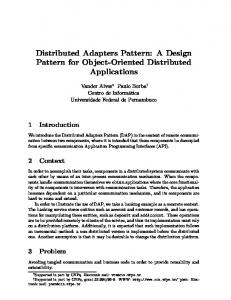
Fig.1 Formation of pattern for a given configuration of robots. Dark circles are free robots, hollow circles are unoccupied final positions, dark circles within hollow circles are final positions occupied by robots.
The minimal enclosing circle of the configuration of robots is denoted by C1 and its centre is origin O. We define the robot nearest to origin to be the robot which is at shortest distance greater than zero from origin; similarly we define final position nearest to origin. We denote these two points by NR1 and NF1 respectively. Circle C’ is centred at O and has radius equal to maximum of distance of NR1 and NF1 from origin. When we mention ², we assume it to be a very small positive number. We shall use the said terminology in proving correctness of the algorithm. 4.1
Steps
The order in which robots form the pattern is : 1. If the origin is not a final position and there is a robot at origin, the robot moves away on the positive X-axis. 2. If origin is a final position and there is no robot at the origin, a robot moves to it. 3. Let d be greater of distances of NR1 and NF1 from origin. Robots at distance less than or equal to d move outwards towards boundary of circle, until they are at a slightly greater distance than d from centre. 4. NR1 moves to NF1. 5. If there are unoccupied final positions on boundary of circle, other robots except those which lie at final positions on boundary of circle move to fill the final positions on the boundary of circle.
6
Swapnil Ghike and K. Mukhopadhyaya
6. Robots which are not at final positions move to occupy the free final positions. Algorithm NoCompass ensures following while forming the pattern: – At a time only one robot moves. – The circle C1 remains intact as an invariant until the pattern is formed. – If origin is a final position, then agreement by robots on XY axes and origin remains invariant after a robot moves to centre of circle, until pattern is formed. – If origin is not a final position, then the agreement by robots on XY axes and origin always remains an invariant until the pattern is formed. Figure 1 illustrates formation of a pattern where steps 2, 4, 5, 6 are followed. In diagram A, NR1 moves towards it since there is a final position at origin. In diagram B, the new NR1 moves to NF1. Thus the agreement on XY axes changes and then it remains invariant until pattern is formed. Diagram C shows that robots fill peripheral final positions without breaking C1 and diagram D shows how the rest of final positions are occupied. Arrows indicate direction of movement of robots. Numbers in increasing order over arrows indicate the order in which robots reach final positions. 4.2
Correctness of Algorithm NoCompass
Theorem 1. All the robots agree on orientation of pattern to be formed in their local coordinate systems. Proof: According to Algorithm NoCompass (lines 1 to 10), every robot r first forms a minimal enclosing circle C1 of initial configuration of robots. It also plots the pattern to be formed in its own local coordinate system. First r forms a Complete Graph G by connecting all points of the input pattern with each other. If there are n points in G, there will be a total of n*(n-1) segments possible by joining these points. Every robot r identifies the smallest segment in this graph G, we call this segment S. Then r plots S on its own local positive X-axis from 0 to 1. Both end points of S form n-2 segments each (which do not include S). Out of these 2*(n-2) segments, r selects smallest segments, let it be called S’. Then r plots S’ in its local coordinate plane such that S’ makes acute angle with local positive Y-axis and arranges the pattern in its local view such that the local origin lies at intersection of S and S’. Ties are broken by (length, angle with local positive Y-axis) pair. Thus, every robot has now the same orientation of local pattern about Y-axis. Also the requirement that S’ makes an acute angle with local positive Y-axis means that all robots agree on orientation of local pattern about X-axis. Finally, agreement on origin to be the Intersection of S and S’ ensures that all robots share a same view of pattern in their local coordinate systems. Then r plots a minimum enclosing circle C2 of the local pattern. Theorem 2. Before beginning movement of robots, all the robots agree on the orientation and scale of pattern to be formed.
Pattern Formation with No Agreement on Coordinate Compass
7
Proof: In Algorithm FindFinalPositions, centre of C2 is shifted to centre of C1 and accordingly pattern points are shifted. Then C2 is compressed or expanded to overlap C1. Depending on the extent of change of diameter of C2, the points of local pattern are also relocated to their new locations. A minimum enclosing circle of a set of points has two or more of those points on its boundary. Thus there are now two or more robots as well as two or more pattern points on boundary of C1. Now every robot agrees on the centre of these circles as the origin. Thus now with an agreement on origin in place, we need to take care that all robots agree on orientation of the pattern about origin. All robots agree on direction of positive X-axis to be the ray from O to NR1. Every robot rotates its local pattern such that pattern point closest to origin lies on this agreed positive X-axis. Now there are two possible directions of positive Y-axis out of which robots must agree on one direction. In both cases, they find out smallest angle M and M’ made by a pattern point on boundary of C1 with the agreed positive X-axis. The direction corresponding to smaller angle out of these two is agreed as positive Y-axis by all robots. Thus all robots agree on XY axes and origin, thus they have same view of pattern to be formed in physical 2-dimensional plane. The two angles M and M’ can turn out to be equal. This tie can be resolved as follows:- NR1 moves slightly towards its local positive X-axis such that it stays nearest to the centre. Thus the tie resulting out of symmetry can be broken. Until this symmetry is broken, no other robot should be allowed to move. However we have not included this mechanism in our algorithm in this paper. Possibility of tie among robots while selecting the nearest robot has not been resolved. Theorem 3. Starting from the initial configuration I0, the robots form a configuration I1 in finite time (i.e. in finite number of cycles) such that NR1 is at NF1. Proof: There can be four independent cases: 1. If the origin is not a final position and there is a robot at origin, the robot moves away on the positive X-axis. (lines 18 to 21) 2. If the origin is a final position and has a robot, robot stays there. (lines 18 to 21) 3. If origin is a final position and has no robot, NR1 will move there. (lines 22 to 27) 4. Origin is not a final position and there is no robot at the centre. In this case, let d be maximum of distance final position nearest to centre of C1 and distance of the robot nearest to centre. Robots at distance less than or equal to d move outwards towards boundary of circle, until they are at a slightly greater distance than d from centre. (lines 46 to 56) Refer proof of Theorem 4. Then NR1 moves to NF1 (line 28 to 33).Until these robots reach their destinations one by one, no other robot moves (lines 35 to 40, 45 to 50). Thus the configuration I1 is formed. Since for forming I1, finite distances are covered by robots in straight line fashion, I1 is formed from I0 in finite time.
8
Swapnil Ghike and K. Mukhopadhyaya
Theorem 4. Algorithm MoveRadiallyOut moves robots at distance shorter than |O−N R1| and |O−N F 1| away towards boundary of C1, while avoiding collisions. Proof: Algorithm MoveRadiallyOut selects a single robot based on its polar coordinates and moves it away toward boundary of C1. While doing it avoids collisions by not selecting destinations as the points on circle centred at O of radius of rad + ² which already have a robot (lines 5 to 11). The algorithm also ensures that robots further from O are moved first (lines 1 to 5), hence a robot has no need to take care of collisions before reaching distance rad + ² from O. Theorem 5. Algorithm MoveToDestination always lets the robots reach their destinations in finite time without disturbing the notion of positive X-axis, while avoiding collisions. Proof: MoveToDestination ensures that robots in FR move to final positions in FT one by one without getting closer to O than NR1 standing at NF1. This algorithm selects a pair of free robot R and unoccupied final position T such that the angle made by them at O is least (line 1). If the line R-T does not intersect the circle C’ centred at O of radius NF1 + ², then R reaches T in finite time. If the line R-T intersects C’, then R travels on the tangents to C’ such that path to T is shortest (lines 17 to 22).
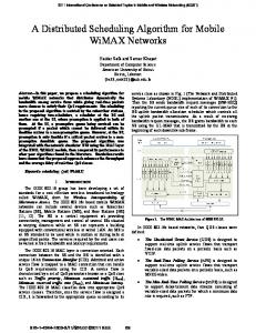
Figure 2. In spite of their oblivious nature, MoveToDestination ensures that robots reach their target points in finite number of cycles.
In figure 2, outer circle is C1 and inner circle is C’. R should ideally reach point X and then point T as given in figure 2.A. But as seen in figure 2.B, if R stops somewhere at a point M on segment AX since it has already travelled maximum permissible distance in a single cycle, then in the next computation cycle R will compute the destination to be X’ instead of X. This may happen because of the oblivious nature of robots according to CORDA model. Though this may happen multiple times, and R may keep on computing new intersections Xs of new tangents, still at some definite point of time R is bound to reach one of the Xs within finite number of cycles since it must travel a finite positive amount of distance in every cycle. After reaching a intersection point X, R will reach T in finite time in straight line fashion (lines 25 to 30). The robots which are between C1 and C’ do not move if they are on final positions. So the set of OBS OB
Pattern Formation with No Agreement on Coordinate Compass
9
remains does not change as R tries to reach T. Thus R avoids OBS by travelling to a point P, which lies just by the side of obstacle and not on or within circle C’, such that there is no obstacle on segment P-T. Thus in any case, R will reach T in finite time while avoiding collisions. Also any robot in FR never gets closer to O than NR1. Hence the notion of positive X-axis is not disturbed. Theorem 6. From configuration I1, the robots form a configuration I2 in finite time such that NR1 is at NF1 and final positions on boundary of C1 are occupied. Proof: Algorithm NoCompass (lines 45 to 50) suggests that robots on boundary of C1 don’t move unless all the final positions on boundary are occupied. This is important to maintain C1 as invariant. So only the robots strictly within boundary of C1 and not the nearest ones to O can move. One of these robots moves to final positions on boundary according to Algorithm MoveToDestination. After this, NoCompass (lines 60 to 66) forces another robot to reach a point on boundary of C1. Thus I2 is formed in finite time. Theorem 7. From configuration I2, the robots form a configuration I3 which is same as the pattern to be formed. Proof: Once final positions on boundary of C1 are occupied, free robots use Algorithm MoveToDestination to reach the unoccupied final positions. At the same time, robots already at their final positions will not move. Thus from proof of Theorem 5, we can say that I3 is formed in finite time. Theorem 8. Starting from configuration I0 until the pattern is formed, agreement on origin remains an invariant. Proof: From Theorem 6, we see that unless all the final positions on boundary of C1 are occupied, no robot on boundary of C1 moves. Hence C1 remains an invariant, which implies its centre - Origin remains an invariant. Theorem 9. If origin is not a final position, then starting from configuration I0 the agreement by robots on XY axes always remains an invariant until the pattern is formed. Proof: The agreement on X-axis can get disturbed if notion of robot nearest to origin gets disturbed because of one these resons: 1. NR1 travels away from origin so that it no longer remains nearest to origin 2. Another robot comes closer to origin than NR1. As seen in Theorem 3, NR1 does not move until other robots have moved sufficiently away from origin. Theorems 5,6,7 indicate that this robot does not move again after reaching its destination. Thus first case does not occur. Second case has also been taken care of as seen in proofs of Theorems 5 and 6. Hence X-axis is agreed upon by all robots and maintained as an invariant. From proof of Theorem 2, we can see that direction and orientation of Y-axis remains invariant since the locations of final positions are dependent on origin and X-axis. Since origin and X-axis are an invariant, hence agreement on Y-axis is also invariant.
10
Swapnil Ghike and K. Mukhopadhyaya
Theorem 10. If origin is a final position, then the agreement by robots on XY axes remains invariant after a robot moves to centre of circle, until pattern is formed. Proof: The agreement on X-axis can get disturbed if origin is one of the final positions, since NR1 should move to it. But once the final position at origin is occupied, robots agree on a new X-axis and there is no way to disturb this new agreement (Theorem 8). Thus there is a new agreement on Y-axis as well and it remains an invariant until pattern is formed (theorem 9). Note that agreement on origin is never disturbed whether origin is a final position or not. Theorem 11. NoCompass ensures that only one robot moves at a given time. Proof: Referring to steps of NoCompass and said proofs, we see that at a time only one robot moves: Step 1 and step 2 (Theorem 3), Step 3 (Theorems 3 and 4), Step 4(Theorem 3), Step 5(Theorems 5 and 6), Step 6(Theorems 5 and 7).
5
Conclusion
The arbitrary pattern formation problem has been successfully solved by researchers for the cases of partial and full agreement on coordinate compass. But not much has been algorithmically stated about the no agreement case, beyond theoretically proving that arbitrary pattern formation is not possible in case of no agreement. We have proposed an algorithm that can form a large range of patterns, hence it can be used in the most practical scenario where robots may not share any sense of orientation at all. The limitations of our algorithm are: – A possible tie in selecting the robot nearest to origin is not resolved. – If there are not sufficient robots to occupy free final positions on boundary of C1, then the pattern cannot be formed. Maintaining C1 as an invariant is the crucial premise to successful formation of pattern. We are working toward removing these limitations. The first case may not occur in most of the practical cases since exact equality of distances in a practical pattern formation is rare, or can be avoided with a small deviation from ideal measures. Our main task is to improve the algorithm to remove second limitation, by being able to identify the free robots on boundary of C1 which can be moved without breaking C1 itself. If this is achieved, it will imply that Algorithm NoCompass will be able to practically form almost every pattern of robots.
6
References
1. P. Flocchini, G. Prencipe, N. Santoro, P. Widmayer: Hard tasks for weak robots: The role of common knowledge in pattern formation by autonomous mobile robots, in: Proc. 10th International Symposium on Algorithm and Computation, ISAAC 99, (1999) 93102. 2. G. Prencipe: Distributed coordination of a set of autonomous mobile robots, Ph.D Thesis, University of Pisa (2002)
Pattern Formation with No Agreement on Coordinate Compass
11
3. I. Suzuki, M. Yamashita: Distributed anonymous mobile robots - formation and agreement problems, in: Proc. 3rd Colloqium on Structural Information and Communication Complexity, SIROCCO 96 (1996) 313330 4. I. Suzuki, M. Yamashita: Distributed anonymous mobile robots: Formation of geometric patterns, SIAM Journal on Computing 28 (4) (1999) 13471363. 5. G. Beni, S. Hackwood: Coherent swarm motion under distributed control, in: Proc. 1st. Int. Symp. on Distributed Robotic Systems, DARS92 (1992) 3952 6. L.E. Parker: Adaptive action selection for cooperative agent teams, in: Proc. 2nd Int. Conf. on Simulation of Adaptive Behavior, MIT Press (1992) 442450 7. T. Balch, R.C. Arkin: Motor schema-based formation control for multiagent robot teams, in: Proc. 1st International Conference on Multiagent Systems, ICMAS95 (1995) 1016. 8. P. Flocchini, G. Prencipe, N. Santoro, P. Widmayor: Arbitrary pattern formation by asynchronous, anonymous, oblivious robots, in: Theoretical Computer Science 407 (2008) 412447 9. N. Agmon, D. Peleg: Fault-tolerant gathering algorithms for autonomous mobile robots, SIAM Journal on Computing 36 (2006) 5682 10. P. Flocchini, G. Prencipe, N. Santoro, P. Widmayer: Gathering of asynchronous robots with limited visibility, Theoretical Computer Science 337 (13) (2005) 147168.
7
Appendix A
Algorithm MoveRadiallyOut(O, rad, ²) C := Circle of radius rad centred at O; C’ := Circle of radius rad+ ² centred at O; If There Is a robot ri other than Me within C’ such that (|O − ri|, Angle(P ositiveX − axis, O − ri)) > (|O − r|, Angle(P ositiveX − axis, O − r)) Then destination :=null; EndC. (5) Else p := Point on C’ such that there is no robot at p; If There is an obstacle at p Then destination := Point on C’ just by the side of p; Else destination :=p; EndC. (10) End MoveRadiallyOut. Algorithm MoveToDestination(FR, FT, OB, NF1,C1) (r , p) := MinimumAngle(FR, FT); /* It choose pair (r,p) such that Angle(Or, Op) = minAngle(Or’, Op’) r’ ² FR, p’ ² FT
Ties are broken by (radial distance, anticlockwise angle) pair */ C := Circle of radius |O − N F 1|+ ² centred at O; If I Am Not r (5) Then destination:= null; EndC. Else /*I Am r */ If Line passing through r and p Does Not Intersect circle C
12
Swapnil Ghike and K. Mukhopadhyaya
Then If No Obstacle Is on the Line passing through r and p (10) Then destination:= p; EndC. Else Safe := (Circular area of C1 - Circular area of C); d: = Point strictly inside Safe Not occupied by any Obstacle, and such that No Obstacle Is on segment [d-p]; destination:= d; EndC. (16) Else tr1, tr2 := Tangents from r to C; tp1, tp2 := Tangents from p to C; /* If there is only tangent for r to C, then tr1=tr2. Similarly for p.*/ xij := Points of intersection of tri, tpj ; (21) D := xij corresponding to mintri,trji=1,2 and j=1,2 ; If No Obstacle Is on the Line passing through r and D Then destination:= D; EndC. Else (25) Safe := (Circular area of C1 - Circular area of C); d: = Point strictly inside Safe Not occupied by any Obstacle, and such that No Obstacle Is on segment [d-D]; destination:= d; EndC. End MoveToDestination. (30) Algorithm FindFinalPositions(C1,C2,P1,P2,Pattern) ShiftCentre(); /*Shifts P2 to P1. Accordingly shifts all Pattern points.*/ Pattern1 = SuperImpose(); /*Compresses or expands C2 to overlap C1. */ O := P1; R1 := Robot nearest to O at distance > 0; (5) Positive X-axis := Ray OR1; RotatePattern(Pattern1); /* Rotates given pattern such that Pattern point nearest to O lies on positive X-axis.*/ D1,D2 := Two possible directions of Positive Y-axis; F1,F2 := Two possible choices of Pattern points; (10) Periphery1: = Pattern points on periphery of C1 in case of D1; Periphery2: = Pattern points on periphery of C1 in case of D2; m1 := MinAngle(Positive X-axis, Periphery1); m2 := MinAngle(Positive X-axis, Periphery2); /* It chooses p from Periphery1 / Periphery2, such that (15) Angle(Positive X-axis,Op) :=minAngle(Positive X-axis,Op’)< 180o where p’ ² Periphery1/Periphery2 and returns Angle(Positive X-axis,Op)*/ If m1 < m2 Then Positive Y-axis := Ray OD1; FinalPositions := F1; Else Positive Y-axis := Ray OD2; FinalPositions := F2; (20) AntiClockWise := Direction from Positive X-axis to Positive Y-axis without crossing Negative Y-axis; End FindFinalPositions.