A Distributed Architecture for Data Mining and Integration Malcolm P. Atkinson
Jano I. van Hemert
Liangxiu Han
National e-Science Centre School of Informatics University of Edinburgh, UK
National e-Science Centre School of Informatics University of Edinburgh, UK
National e-Science Centre School of Informatics University of Edinburgh ,UK
[email protected] [email protected] [email protected] Ally Hume Chee Sun Liew EPCC University of Edinburgh, UK
[email protected]
National e-Science Centre School of Informatics University of Edinburgh, UK
[email protected]
ABSTRACT
1.
This paper presents the rationale for a new architecture to support a significant increase in the scale of data integration and data mining. It proposes the composition into one framework of (1) data mining and (2) data access and integration. We name the combined activity “DMI”. It supports enactment of DMI processes across heterogeneous and distributed data resources and data mining services. It posits that a useful division can be made between the facilities established to support the definition of DMI processes and the computational infrastructure provided to enact DMI processes. Communication between those two divisions is restricted to requests submitted to gateway services in a canonical DMI language. Larger-scale processes are enabled by incremental refinement of DMI-process definitions often by recomposition of lower-level definitions. Autonomous evolution of data resources and services is supported by types and descriptions which will support detection of inconsistencies and semi-automatic insertion of adaptations. These architectural ideas are being evaluated in a feasibility study that involves an application scenario and representatives of the community.
We report the rationale for a new architecture, DMI architecture, for combined data integration and data mining under development in the ADMIRE project1 . The principal innovations are: (1) a de-coupling of the enactment technology from the tools used to prepare DMI processes, which in turn enables (2) multiple independent DMI enactment services, some of which may be tightly coupled with curated data collections, and (3) the enactment of each DMI process by distributing it over these services, c.f. distributed queries. The DMI architecture is intended to enable society to make better use of the rapidly expanding wealth of data. The number of sources of data is increasing, while, at the same time, the diversity, complexity and scale of these data resources are also growing dramatically. This cornucopia of data offers much potential; a combinatorial explosion of opportunities for knowledge discovery, improved decisions and better policies. Today, most of these opportunities are not realised because composing data from multiple sources and extracting information is too difficult. The proposed DMI architecture must make all of the stages of DMI process development and enactment as identified in [14] easier and more economic. This data-rich environment with a growing commitment to the effective exploitation of data requires an architecture that must simultaneously address a number of sources of scale and complexity. The following list is indicative: • The scale and complexity of each data source grows. The DMI architecture addresses this with data-flow technology to reduce data handling and to move data reduction and transformation operations closer to data sources. These data transformations can be updated to prevent changes in the forms of data provided by a data resource from propagating to other parts of a DMI workflow unnecessarily. • The number and variety of independent data sources increases. As warehousing and virtualisation become infeasible at the envisaged scale, which we address by proposing dynamic composition of processes. • The computational complexity of extracting information grows as a result of the above and of increasingly sophisticated application requirements. The DMI architecture ad-
Categories and Subject Descriptors C.1.4 [Parallel Architectures]: Distributed architectures
General Terms Algorithms, Design, Languages
Keywords Data mining; Data integration; Distributed computing; Dataaware Distributed Computing; Service-oriented architectures
Permission to make digital or hard copies of all or part of this work for personal or classroom use is granted without fee provided that copies are not made or distributed for profit or commercial advantage and that copies bear this notice and the full citation on the first page. To copy otherwise, to republish, to post on servers or to redistribute to lists, requires prior specific permission and/or a fee. DADC’09, June 9–10, 2009, Munich, Germany. Copyright 2009 ACM 978-1-60558-589-5/09/06 ...$5.00.
1
INTRODUCTION
EU FP7 ICT 215024 www.admire-project.eu
dresses this by enabling the work of data-aware distributed computing (DADC) engineers and by supporting the incremental definition and revision of libraries and patterns. • The number of application domains using DMI grows, becomes more diverse and engages more users. The DMI architecture addresses this by recognising communities of users, by supporting them with their own environments and by delivering packaged production versions of DMI processes. • The number of experts involved in developing new DMI processes and supporting their application grows. The DMI architecture addresses this by separating support for DMI experts from that for DADC engineers and applicationdomain users. Support for communities with aligned DMI interests is achieved by enabling sharing between DMIdevelopers’ workbenches via a common registry for their community. • The number of providers of data and DMI services grows. The DMI architecture separates the organisation of environments for DMI-process development from the complexities of DMI-service provision by interposing DMI gateways using a canonical language. • The growing sophistication of information extraction from large bodies of data requires ever more complex and refined workflows. The DMI architecture addresses this by structuring collections of components into libraries that correspond to a conceptual structure captured in DMI ontologies and by supporting the incremental refinement of libraries and the DMI processes that use them. This encourages greater contemporaneous effort by supporting concurrent independent development by three separate categories of experts working both for providers and users. • The providers of data and services autonomously change their offered services and schema at a rate which defies manual adaptation when many data resources are in use. The DMI architecture proposes to exploit type systems, semantic description, community effort and light-weight composition to semi-automatically adapt to change and to pool the intelligence of human interventions. Definitions are in Table 1. The principal elements of the architecture are presented in Section 2. Section 3 introduces the canonical language used to send requests to DMI gateways. The evaluation of the DMI architecture using prototypes and test cases is described in Section 4. Related work is summarised in Section 5 and Section 6 concludes with an assessment of progress and the plans for further work. More detailed information about the architecture and the work underway in the ADMIRE project to evaluate it can be found in [5].
2.
DMI ARCHITECTURE
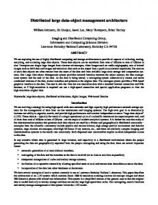
Figure 1 shows how the complexities of matching the diversity of user requirements at the tools level can be separated from the complexity of the enactment level, accommodating the diversity of data resources and services, by interposing the single canonical domain of discourse represented by the DMI language (see Section 3). Our hypothesis is that, by enforcing this logical decoupling, both the tools development and the platform engineering will proceed rapidly and independently. Of course, this depends on the quality of the abstract machine and the language operating at the gateway. Developing that quality is a research goal.
component
a computational item used in a DMI, i.e. data collections, data resources, functions, PE, PE instances & types. connection a pipe streaming data between PE. CRISP-DM six phases of data mining [14]. data collection a coherent collection of data, e.g. a file, a set of files, a relational table, a set of tables, an XML document, etc. data resource a service that provides data and may accept data, e.g. a file service or a DBMS. DADC engineer a person who builds distributed systems that dynamically adapt to the data they handle. DMI experts specialists in developing DMI process. domain experts specialists in applying DMI in their domain. DMI gateway a service that processes DMI requests. DMI portal an interface for submitting canned DMI requests. DMI process a sequence of computational steps to a DMI goal. enactment a computation implementing a DMI process. library a collection of PE, functions and types. pattern a recurring structure within DMI processes. processing element an algorithm for a step in DMI (abbr: PE). PE instance a PE plus its processing state. registry holds descriptions of all the possible DMI components. repository holds definitions and implementations of all of the DMI components that are generated within the DMI architecture. session a dynamically created service providing access to parts of the state of an enactment. streaming passing values incrementally along a connection. type a formal description of a class of values.
Table 1: Definitions used in this paper
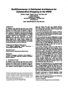
We propose supporting user interaction with DMI systems through two mechanisms: • DMI workbenches that support a coherent set of tools designed to support a particular category of DMI-process developers. DMI workbenches may take many forms to support particular developer styles and application-developer requirements. • DMI portals that permit application-domain experts to use repeatedly and conveniently DMI processes that have been developed and packaged at the above workbenches. On each occasion that such processes are enacted, users will specify parameters, trigger the submission, observe progress and collect results through carefully prepared user interfaces. The design and provision of DMI workbenches and portals will be reported elsewhere. To allow providers of DMI services to amortise and smooth their costs over many communities of users and to allow selection of DMI services from multiple providers, the DMI architecture provides a manyto-many relationship between workbenches (and portals they have set up) and the DMI gateways, as is shown in Figure 2. A community of developers will use a number of workbenches, e.g. A, B & C, will all use one registry 1, which holds descriptions of the DMI components that they are developing or have obtained from the gateways they are using, .e.g, a and b. Some of these descriptions will refer to representations of implementations in a repository N. A gateway has its own registry which describes all of the resources, services and components it is able to work with. Requests to a gateway can interrogate this information, can update it
User and application diversity
Iterative DMI process development Tool level
Gateway interface one model
Accommodating Many application domains Many tool sets Many process representations Many working practices
B workbench
A workbench
b Gateway 1
a Gateway
DMI canonical representation and abstract machine
Mapping optimisation and enactment
Composing or hiding Many autonomous resources & services Multiple enactment mechanisms Multiple platform implementations
Repository
System diversity and complexity
Gateway
2 registry
registry N
c Enactment level
C workbench
3
4 registry
registry
Figure 2: Relationships between workbenches, gateways, registries and repositories
Figure 1: Separating DMI levels of diversity and can cause DMI processes that use the gateway’s capabilities to be enacted. A gateway may present services that are obtained by delegating work to other gateways; shown as a delegating to c in Figure 2. Each gateway has its own registry so that its services can evolve independently. We envisage a large, distributed population of DMI gateways with a variety of owners and purposes, and with varying policies on the adoption of new versions. Hence a registry is associated with each gateway. It is both undesirable and infeasible to postulate a universe of gateways that evolve in unison. Workbench C may be connected to both a and b so that it can draw on different services provided by these, or to deliver its definitions of DMI components and processes to both a and c, or to mediate the transfer of descriptions between a and c. The ADMIRE architecture develops from service-oriented architectures and imposes further discipline shaped by familiar service-oriented architectures [20] and distributed computing [27] principles, that are then interpreted in terms of the workloads of DMI. DMI Gateway. A DMI gateway hides internal complexity so that it may be re-engineered later. It polices the acceptance of requests to conform with resource limitations, load levels, security enforcement, etc. Delegation hiding. Part or all of a request may be delegated to other DMI gateways, without the requester being aware of the delegation. Delegation should not impose unnecessary data transfers or control messages. Monitoring and status data must be mediated via aggregators that reverse the delegation mapping. Recursive composition. DMI components may be composed to define a DMI process. Such compositions may be used as DMI components. Data-flow composition. The DMI activities are composed by connecting data sources with data consumers. Data sources may be a specified data extraction from a data resource, a third-party transfer or an output from a DMI component. Data consumers include update operations on data resources, third-party transfers or an input to a DMI component. Normally, the order of enactment and the opportunities for parallelism are inferred from the dependencies in these data flows.
Typed composition. The DMI system uses a multi-layer type system to validate the composition of components in all DMI-process definitions, particularly their use of recursive and data-flow compositions. Abstracted data flow. Logically, a data flow is a pipe carrying a sequence of values, a data stream, from its source to its consumer, with buffering to cope with different production and consumption rates. This has the same logic whatever the scale and type of the data transfer. The implementation may use any granularity and pass data by reference or by copy. Data substitutability. Any data flow, i.e. the sequence of values passing along a data stream, may be saved for diagnosis or re-use. Sampling support. Random, initial, terminal and periodic sampling should select a proportion of data during data exploration and DMI process development. For example, Szalay stated that data should be explored with 1/10000 of the data and then with 1/100 before full analysis [9]. Provenance support. The DMI system must support mechanisms for collecting provenance information. DADC patterns. Frequently used DMI-process design patterns should be recognised, exploited by DMI experts and efficiently implemented; Examples include: • pipelines • distributed map-reduce • distributed tree-integration of replicated or partitioned data collections • parallel all-meets-all computation (e.g., all-pairs) • multi-site visit and collect Semantic and type description. DMI data collections, data resources and components should be well described in terms of their semantics and types to allow validation of the correctness of compositions of DMI activities and use of data. These descriptions will track differences between versions of components and equivalence between components to support optimisation and semiautomatic adaptation. DMI Gateways accept requests in one uniform language, which we call the DMI Language (DMIL). The next section introduces this language.
3.
DMI LANGUAGE
The DMI language (DMIL) provides a notation for all DMI requests to a gateway. It encodes the following: • Requests for information about the services, data resources, data collections, defined components (processing elements (PE), functions and named types) and libraries supported by the gateway. • Definition, redefinition and withdrawal of any of the above, i.e. the capabilities of a gateway can be dynamically tailored. • Submission of requests to enact a specified data mining and integration process. The descriptions of DMI processes are compositions of existing PE that already perform tasks, such as: querying a data resource, transforming each tuple in a sequence, merging two input streams, removing anomalies, normalising, classifying, transforming a result stream to superimpose results on Googlemap, etc. New composite PE can be defined by composing other PE and registered for future use. Registered components can be collected together to form a library that supports a particular data integration, data mining or domain-specific class of processing steps. Such a library can be installed on any gateway that supports the components on which it was built. A reinstall operation allows a new version of a library to supersede a previous version. The processing of a DMI request involves: 1. Decide, on the basis of attached credentials, resource availability and so on, whether the request is one which this gateway is prepared to run. If the enactment can go ahead, send the requester an acceptance acknowledgement and create a reference to the session service that will support monitoring [8]. 2. Validate the request to verify: (a) it is a valid DMIL sentence, e.g. that all the inputs and outputs of PE are defined and their types match, (b) that physical components exist or can be created that can perform as requested, and (c) that the gateway’s descriptions of those components are compatible with the annotation in the request. 3. Organise the computation by: (a) performing high-level pattern expansion (evaluation of DMIL functions) and planning (high-level optimisation), producing DMI processes to be run within the regime of this gateway and coupled DMI processes to be submitted to other gateways. (b) submiting the delegated processes setting up intergateway data streams, (c) optimising the local DMI processing elements, mapping abstract component. to physical components, taking account of data properties, locality, resource requirements and performance. 4. Initiate the enactment, and replace any processes that are not accepted by another gateway to which they were delegated. Furthermore, if the request contained any register, install, reinstall or withdraw statements, transactionally update the registry accordingly [4]. 5. Coordinate, monitor and supervise the enactments, maintaining integrated status information so that it can then be interrogated by the requester. Deal with issues that arise during enactment, such as failures by dynamically rearranging the enactment. 6. Terminate the enactment, preserve data still to be collected and tidy up using resource-lifetime management [30].
/* import components */ use dmi.rdb.SQLQuery; use dmi.samplers.ListRandomSample; use dmi.image.ImageRescale; .. . use dmi.classifiers.nFoldValidation; use dmi.classifiers.LDAClassifier; /* set up and identify instances of the PE */ SQLQuery sqlQuery = new SQLQuery; ListRandomSample listSample = new ListRandomSample; TupleProjection tupleProj = new TupleProjection; GetFile getFile = new GetFile; ImageRescale imageRescale = new ImageRescale; MedianFilter medianFilter = new MedianFilter; WaveletDecomp wavelet = new WaveletDecomp; TupleMerge tupleMerge = new TupleMerge; ViaStatus deliver = new ViaStatus; String query = “SELECT fileName, . . . FROM EURExpress.images, . . . WHERE . . . ”; /* the literal “query” gets connected to sqlQuery’s input “expression”*/ |- query -| => expression->sqlQuery; /* sqlQuery’s output “data” gets connected to listSample’s input “dataIn” */ sqlQuery->data => dataIn->listSample; |- 0.01 -| => fraction->listSample; Connection c1; listSample->dataOut => c1; c1 => filename->getFile; c1 => data->tupleProj; |- [“date”, “assay#”, . . . ] -| => columnIds->tupleProj; getFile->data => dataIn->imageRescale; imageRescale->dataOut => dataIn->medianFilter; |- repeat enough h 300, 200 i -| => size->medianFilter; medianFilter->dataOut => dataIn->wavelet; wavelet->dataOut => dataIn[0]->tupleMerge; tupleProj->result => dataIn[1]->tupleMerge; Validation val = nFoldValidation (10, LDAClassifier); tupleMerge->dataOut => data->val; val->results => data->deliver; Figure 3: An example of DMIL that corresponds with the process in Figure 6 The DMIL is primarily used to define graphs and functions that generate these graphs dynamically. The nodes of graphs are processing elements (PE) that perform functions such as extracting data from databases and files, transforming data and performing data-mining algorithms. The directed arcs, called connections, denote a data flow from a specified output of one PE to specified inputs of one or more PE. A literal data stream notation in DMIL denotes a sequence of values to be delivered to a connection or specified input. Parameters to functions can specify other functions, PE, PE instances, data resources, data collections, controls for generating literal data streams, sampling rates, repetition and parallelisation targets and so on. The functions simplify the abstract machine by serving purposes perceived as different by DMI users, DMI developers, DADC engineers and interaction tools, e.g. they represent: • composite PE, built by connecting other PE, where they hide internal information and prevent ambiguity over naming multiple PE instances;
• a packaged DMI-process definition that can be parameterised and activated through a portal (a deployed DMI process in CRISP-DM jargon [14]); • an encoding of a pattern, such as: repetition, parallilisation, all-meets-all, etc.; and • an encoding of an optimisation strategy. DMIL supports a two-level type system: structural types and domain types. The structural types define the base types and structures for the graph production. These are the same in every application context and structural type equivalence must be satisfied for these types for every DMIL operation. The domain types represent the types used in data mining and those specific to application domains, e.g. the result of a classification algorithm and a 3D fMRI brain image respectively. It is infeasible to hypothecate a single universe of domain types spanning all applications. Instead we assume that there will be a common universe of “basic” types that are available in all domains, a universe of data-integration and data-mining types that support their standards and independent extensions (that may overlap) for each application domain. Structural type equivalence is therefore infeasible in this context and so a nominative type system is used [28]. Ontologies describing the domain types will define acceptable type inclusion. These semantically defined domain types are used to verify that types supplied to an input of a PE are compatible with requirements on that input. This is predominantly based on the descriptions of PE held in registries, which define the set of named inputs and outputs of the PE and the domain types each input accepts. The domain types of each output are described, sometimes in terms of the types supplied to the inputs. By tracing the flow through the graph it is possible to propagate the information known about types and to verify compatibility. In some cases very little can be inferred about an output, e.g. when reading from an arbitrary file. In these cases, the developer has to annotate the connection with the type the data represents. Frequently, the PE is agnostic about components of a value, e.g. fields in a tuple it doesn’t process, in which case use is made of type any in the description. The example of a DMIL request in Figure 3 encodes part of the workflow that expands to the OGSA-DAI shown in Figure 6, which is explained in Section 4. The mapping from DMIL to the diagram is straightforward and consists of systematically importing the relevant components from the relevant library, instantiating them as many times as is needed and then connecting them via their outputs. The literals illustrate our sequence notation. In this example the pattern for n-fold validation has been encoded as the function nFoldValidation. When this is called, with the number of validations and a classification builder as its parameters, it generates an evaluation graph equivalent to the lower part of Figure 6, except that the figure for reasons of clarity shows only one validation, whereas the DMIL below would generate 10 instances of that graph if it chose maximal parallelism.
4.
FEASIBILITY STUDY
We are assessing the feasibility of the DMI architecture by iterating over: 1. building prototypes of the architecture; 2. mapping test DMI processes from the case study scenarios into DMIL;
3. submitting these as DMI requests and observing enactment performance; and 4. analysing the effectiveness of the architecture in separating concerns, delivering functionality, providing change management and accommodating change. OGSA-DAI [3] already implements data streaming graphs interconnecting its PE, termed “activities”, and was an inspiration for the DMI architecture. Therefore, the initial prototype, which is being used to explore data streaming for DMI, maps DMI requests to sets of OGSA-DAI requests. Each OGSA-DAI request represents a subgraph of the DMI request that will be run on one OGSA-DAI service. These are coupled together, using OGSA-DAI’s inter-process data streaming. All of the activities in one OGSA-DAI request are started simultaneously and execute in a pipelined manner as data arrives at their inputs. Within an OGSA-DAI request, data is passed between activities as references to Java objects. These are serialised for inter-process data streaming. This leads to efficient processing of arbitrarily large data with a small memory footprint.
4.1
An example test DMI process
The EURExpress-II project provides one of the use cases from which we draw DMI processes to evaluate our architecture. It aims to build a transcriptome-wide atlas for the developing mouse embryo using RNA in situ hybridisation experiments. To date it has collected over 500,000 captured images (∼ 4TB) of these experiments, which are then annotated by human curators. The annotation consists of tagging each image with terms from a set of 1,500 anatomical components. Tagging an image with a term means a particular gene is expressed in the corresponding anatomical component. So far, 80% of images have been manually curated. Our chosen test DMI process automatically performs annotation by first creating a classifier for each term and then classifying the remaining 20% of images in terms of anatomical terms, where each image may map the expression of multiple genes. The high-level DMI process is essentially a pattern recognition task. The aim is to produce multiple classifiers, where each classifier recognises for each image whether it shows gene expression in one anatomical component. As shown in Figure 4, it has three phases: training, testing and deployment. These can be further divided into sub-processes. For instance, for training the pattern recognition, the subprocesses include image processing, feature generation, feature selection/extraction and classifier construction. The testing phase reuses and repeats the first three sub-processes and adds an evaluation step. The deployment phase contains only the apply classifier process. We describe in more detail the processing steps. Image integration: combines the manual annotations with corresponding images. Image processing: applies median filtering to reduce image noise and re-scales images to a standard size producing standardised images represented by 2D arrays. Feature generation: uses wavelet transformation to generate features, which consist of matrices of wavelet coefficients; these are stored for re-use. The number of features generated using wavelet transform is large, e.g. an image of 300 × 200 pixels will generate 60,000 features. Feature selection/extraction: reduces the feature sets by selecting significant features and applying dimensional-
Testing phase
Manual Annotations
Image integration
Image processing
Training phase
Image processing
Feature generation
Images
Feature generation
Deployment phase
Feature selection/ extraction
Feature selection/ extraction
Prediction evaluation
Classifier construction
Figure 4: EURExpress-II abstract DMI process
Apply classifier
Automatic annotations
ity reduction to obtain representative feature vectors. Here we use FisherRatio analysis and independentcomponent analysis, respectively. Classifier construction: trains a classifier to associate each image with a particular anatomical term. A classifier takes the features of an image as input and outputs for the anatomical component one of the following: not detected, possibly detected, weakly detected, moderately detected or strongly detected. The classifier algorithm is linear-discriminant analysis. Prediction evaluation: takes the classifier from the training phase and applies it to a set of testing data to calculate its predictive power. Apply classifier: takes the best classifiers and uses these to automatically annotate images that have not yet undergone curation.
4.2
Mapping to a detailed DMI process
Applying data-mining techniques to construct and evaluate a classifier from a set of tuples containing feature values and the desired classification output is considered a standard data-mining pattern. An OGSA-DAI workflow that captures this pattern is shown in Figure 5. The specification of which data set to mine is expressed using an SQL query that extracts the annotation data from a database. It is assumed that the query returns a set of tuples where each tuple has m fields, the first m − 1 fields are feature values and the m-th field is the desired classification output. Another common pattern is to randomly sub-sample the data for rapid experimentation. This reduced data set can now be cleaned or pre-processed in whatever manner is appropriate for the domain. This domain-specific pre-processing stage is shown as an abstract PE in the workflow diagram. These abstract PEs will be replaced with concrete PEs, or even sub-workflows of PEs in a concrete implementation of the pattern. After pre-processing, the data is randomly split into training and testing sets. The training data is passed to another abstract PE in which both training-specific and domainspecific processing can be carried out. After this, the data is passed to a PE that constructs and outputs a classifier. Meanwhile, in the testing sub-workflow, the tuples of the test data set are projected into tuples that contain only the
Figure 5: Abstract OGSA-DAI workflow showing a common data mining pattern feature values and tuples that contain only the desired classification outputs. The tuples that contain the feature values are passed to an abstract PE that again allows domainspecific processing of the tuples. The training tuples are then passed to the Classify PE that also takes as input the classifier built in the training phase and outputs the classification output of each test tuple. This output is then passed to the evaluation PE that compares these outputs with the desired classification output for these tuples and outputs the classification score. The workflow shown in Figure 5 is a kind of pattern the ADMIRE architecture allows us to express as a DMIL function. With a library of these functions that are understood by a gateway we can produce OGSA-DAI workflows. Clients can focus on providing the domain-specific functionality to populate the abstract PEs in the workflow. For the EURExpress-II use case the concrete workflow containing the domain-specific functionality is shown in Figure 6. Although this is a highly domain-specific workflow it can be written in DMIL in terms of reusable functions that implement the various parts. Here, the common domain-specific pre-processing abstract PE has been replaced with a subworkflow that carries out the various image processing operations. The training-specific processing abstract PE has been replaced with a sub-workflow to score the relevance of each feature, select the n best features and then project the tuple to contain only these features and also the desired classification result. Note also that in the final workflow a concrete decision was made about which classification algorithm to use. The work-
flow explicitly specifies the BuildLDAClassifier PE as the classification PE. The architecture will allow DMI-process developers to omit the selection of a specific algorithm, where a registry will be used to locate an instantiation of an implementation of an algorithm to handle a particular abstract task.
4.3
Figure 6: OGSA-DAI workflow for EURExpress-II
A data streaming philosophy
The architecture is designed using a pipeline streaming philosophy. This approach works especially well when the PEs can process small amounts of data at a time and do not require to store the whole data set in memory at one time. If we consider a PE that must process a stream of tuples then the PEs generally fall into one of three categories: one-in, one-out PEs that process a tuple at a time and produces a corresponding tuple before reading the next one. These PEs are the most desirable in a pipeline streaming model. single-pass, k-in, one-out PEs that read all k tuples before producing a single result value. If the PE implements a single pass algorithm then it reads each tuple only once and does not need to maintain all the tuples in memory. These PEs are less desirable in a pipeline streaming model as they hold up the pipeline but as they often have a low memory footprint they can still operate well in a pipeline streaming context. multi-access, k-in, one-out PEs that read all k tuples before producing a single result value. Additionally these PEs implement algorithms that require multiple accesses to each tuple and hence require that the data be held in memory or repeatedly re-read from disk. These PEs are the least desirable in a pipeline streaming context because they hold up the pipeline and can place large memory requirements on the system. In the workflow shown in Figure 6 most PEs can be categorised as one-in, one-out. A few are single-pass, k-in, one out, i.e. FisherRatio, TopN and Evaluate. The only activity that is multi-access, k-in, kout is BuildLDAClassifier. This offers encouragement that many of the operations required in a data mining scenario fit well into a pipeline streaming model. The workflow shown in Figure 6 has scope for parallel execution, which is even greater if n-fold cross validation is used. In n-fold validation the data is split into n pairs of training and testing sets and most of the workflow would essentially be repeated n times. The ADMIRE architecture is designed to take advantage of parallel processing where it is available but to hide most complexities from end-users. The ADMIRE gateway is able to compile a DMIL request such that it can be executed in parallel on multiple execution engines if these engines are available and the resulting execution is more optimal. Planning such parallelisation requires the DMIL compiler and optimiser to have an extensive amount of performance data and descriptions for each PE. In some places the workflow requires the use of a pipe with an unlimited buffer. These buffers have been explicitly inserted into the workflow as PEs. Ideally users should not be concerned about where such buffers are required. Once again the DMIL will allow the users to ignore such issues and the DMIL compiler will automatically insert these buffers when they are required. Detecting where these unlimited buffers must be inserted requires details about each PE’s input, output and the order in which they are read from and written to.
5.
RELATED WORK
Significant research effort has been invested in the development of distributed data mining and data access and integration systems. All of the effort so far has concentrated on one aspect, either data mining or data access and integration. The outcomes in terms of architecture designs for distributed data mining can be categorised into three-tier, cluster-based, grid-based and cloud-based infrastructures. We give a brief overview of these below. Three-tier client-server: Kensington [15] is an example of this architecture. The client provides interactive visual programming of data-mining tasks, and three-dimensional visualisation of data and analytical models. The application server handles user login and authentication and provides services for: user-object management, enactment, mining component management, database access and data storage. The third-tier server provides high-performance data mining services located on high-end computing facilities that include parallel systems. Discovery net [2] extends the Kensington architecture to make use of grid computing. Cluster-based: Papyrus [7] is an architecture that enables data mining over distributed data sources. It aims to find optimal mining strategies to run on meta-clusters or superclusters. Each node of a cluster decides whether data should be processed locally or sent to another node for processing. Alternatively, a hybrid approach is supported where data is processed to produce an intermediate result that is then sent to another node for further processing. Grid-based: DataMiningGrid [31] is developed using the Globus toolkit. It is compliant with open technology and standards, most notable OASIS-approved standards such as WSRF and the data mining standard CRISP-DM. Its creators claim the system shows high-performance, and is scalable and flexible. Its ease of use was evaluated against a wide range of representative modern data mining systems. Knowledge grid [12] uses basic grid services such as communication, authentication, information, and resource management to build parallel and distributed knowledge discovery tools and services. The architecture is composed of two layers. The Core K-Grid layer implements basic services for the definition, composition and execution of a distributed knowledge discovery applications over the Grid. Its main goals are the management of metadata that describes the features of data sources, third-party, data-mining tools and algorithms. It also coordinates the execution of an application by trying to meet resource requirements. The high level K-Grid layer comprises services to compose, validate, and execute a parallel and distributed knowledge computation. This layer also offers services to store and analyse results. GridMiner [11] is an infrastructure for distributed data mining and data integration in Grid environments. The architecture consists of a service factory for creating and managing services; a service registry for registering services; a data-mining service that provides a set of data mining and data analysis algorithms; a pre-processing service for data cleaning; a presentation service for visualisation of results and an orchestration service for handling the computation. The DAME [6] has proposed a grid-enabled advanced neuralnetwork-based model for searching distributed large data sets within the distributed aircraft maintenance environment. This framework was to enhance diagonosis and prognosis of airoengine problems via using remote Grid services, tools
and human experts. The iRODS [29] is a rule based data management architecture. It is a grid middleware that provides extensibility and customizability for the execution of workflows through user-defined and administrator-defined rules. These rules have been programmed as a set of microservices, which can be composed together for different tasks based on the requirements. These rules may deal with data placement, controlling access, data federation, data in ingestion, etc. Cloud-based: Grossman et al. [22] have developed a cloudbased infrastructure for data mining on large distributed datasets. The approach moves the processing near to the data. In contrast, most grid-based systems transfer data to processes prior to processing, which incurs a performance penalty where bandwidth is limited. The architecture consists of the Sector storage cloud and the Sphere compute cloud. It uses Sector to provide long-term persistent storage to large datasets, which are managed as distributed indexed files. A streaming model was developed where Sphere splits the input files, called Sphere Streams, into data segments and then Sector’s slave nodes process the segments in parallel. The output of each process is returned to the client, written to local disks, or sent to different so-called “bucket” files. Neither Sector nor Sphere provides support for data semantics. It is up to the user to decide how to interpret data. In order for Sphere to split files, index files that explain the record structure need to be provided. A framework [16] that uses MapReduce [18]for data processing on several well-known machine learning algorithms has been proposed, which allows these machine learning tasks to run in parallel on multicore computers. Similarly, an allpair production system [26] exists for data intensive applications such as data mining. The work provides users with a high-level abstraction. It runs on top of a conventional batch submission system and exploits the local storage connected to each CPU. Other cloud-based infrastructures for data-intensive applications include BigTable [13], Google File System (GFS) [21], and Hadoop [10] that couple data and computing resources to accelerate data-intensive applications. The most prominent commercial solution for data access and integration to federated databases is IBM’s Websphere Information Integrator. In the open source space, OGSADAI [23] is a service-based approach that enables access to heterogeneous data resources by providing a homogeneous service interface. Furthermore, it provides a powerful set of data transformations, data integration operations and data delivery options. OGSA-DAI can execute data integration workflows. Alternatively, it supports data federation through its extension OGSA-DQP [1]. A multi-tier distributed data integration architecture [33] has been developed to support enterprise data manipulation. The system provides a logical layer to map a unified logical data model to reconstruct data from independent to dependent sources, which can integrate and aggregate enterprise data that resides in multiple relational databases. The system also provide a tool set to manage and use on-line ad hoc queries and decision support. Additionally, semantic data integration has been incorporated into existing distributed data integration architectures. For instance, OGSA-DAI-RDF [24] has extended OGSADAI access to RDF storage systems such as Jena [25]. SOGSA [17] is a reference architecture for semantic grid, which
extends OGSA defining a lightweight mechanism to allow the use of semantics and provides associated knowledge services to support a wide spectrum of service capabilities. For the past decades, a wide range of workflow management systems have been established to support the construction and management of workflow. For instance, Taverna is a tool for the composition and enactment of bioinformatic workflows and Pegasus is suitable for managing any complex scientific workflow. Some workflow management systems e.g. Kepler provide graphical tools for workflow composition while others require user to construct workflow from text editor using particular workflow languages e.g. BPEL or representation e.g. directed acyclic graph used in DAGMan Condor. Deelman et. al. [19] provides an overview of workflow system features and capabilities with examples taken from existing workflow systems and a taxonomy that characterises and classifies various approaches for building and executing workflows proposes is discussed in [32].
6.
CONCLUSIONS & FURTHER WORK
In this paper, we highlight the problem of the increase in complexity, diversity and scale of data. We introduce a separation of concerns between data mining and integration (DMI) process development and the mapping, optimisation and enactment of these processes. We postulate this separation of concerns will allow handling separately the user and application diversity and the system diversity and complexity issues simultaneously. We introduce an architecture, which as a principal element defines gateways as the point where these two concerns meet. To allow uniformity and inter-gateway communication, each gateway will accept DMI requests in DMIL, a language that allows requests for information about services, components and libraries; definition, redefinition and withdrawal of the prior; and submission of DMI requests. To validate our hypothesis of separation of concerns, we perform a feasibility study that comprises building prototypes of the architecture; mapping DMI processes from case studies into DMIL, submitting these as DMI requests to the architecture, observing enactment performance, and analysing the effectiveness of the architecture in separating concerns in terms of delivering functionality, providing change management and accommodating change. Here we report our findings on the first prototype of the architecture, which is developed using OGSA-DAI. Our first use case involves a DMI scenario in the context of developmental biology where the objective is to predict in which anatomical components gene expression exhibits given images that capture the results of high-throughput in-situ hybridisation experiments. We identify several properties of the resulting DMI processes after mapping them from DMIL, which we argue are common in DMI requests. We explain how these properties can be exploited for optimising DMI processes. Through further use cases we expect to identify more of properties that provide opportunities for optimisation.
Acknowledgements The EU Framework Programme 7 FP7-ICT-215024 funding of the ADMIRE project is key to bringing the partners together and to undertaking the research. The UK Engineering and Physical Sciences Research Council’s sup-
port of the OGSA-DAI, OMII-UK, DIALOGUE projects and the e-Science Institute set up the meetings that led to the ADMIRE community forming and brought the OGSADAI technology to the project.
7.
REFERENCES
[1] Alpdemir, M. N., Mukherjee, A., Paton, N., P.Watson, Fernandes, A. A., Gounaris, A., and Smith, J. Service-based distributed querying on the grid. In Proceedings of the First International Conference on Service Oriented Computing (15-18 December 2003), Springer, pp. 467–482. [2] AlSairafi, S., Emmanouil, F.-S., Ghanem, M., Giannadakis, N., Guo, Y., Kalaitzopoulos, D., Osmond, M., Rowe, A., Syed, J., and Wendel, P. The Design of Discovery Net: Towards Open Grid Services for Knowledge Discovery. Int. Journal of High Performance Computing Applications 17, 3 (2003), 297–315. [3] Antonioletti, M., and Atkinson, M. The Design and Implementation of Grid Database Services in OGSA-DAI. Concurrency and Computation: Practice and Experience 17 (February 2005). [4] Atkinson, M., Brezany, P., Corcho, O., Elsayed, I., van Hemert, J., Janciak, I., Pilana, S., and W¨ ohrer, A. Advanced Data Mining and Integration Research for Europe: Defining Registry Requirements. Tech. rep., ADMIRE, 2009. [5] Atkinson, M., Brezany, P., Corcho, O., Han, L., ´ , L., Hume, A., Janciak, van Hemert, J., Hluchy I., Krause, A., and Snelling, D. ADMIRE White Paper: Motivation, Strategy, Overview and Impact. Tech. Rep. version 0.9, ADMIRE, EPCC, University of Edinburgh, January 2009. [6] Austin, J., Davis, R., Fletcher, M., Jackson, T., Jessop, M., Liang, B., and Pasley, A. Dame: searching large data sets within a grid-enabled engineering application. In Proceedings of the IEEE—Special Issue on Grid Computing (2005), vol. 93(3), IEEE Computer Scociety, pp. 496–509. [7] Bailey, S., Grossman, R., Sivakumar, H., and Turinsky, A. Papyrus: A system for data mining over local and wide area clusters and super-clusters. In Proceedings of the 1999 ACM/IEEE conference on Supercomputing (CDROM) (1999), ACM New York, NY, USA. [8] Banks, T. Web Services Resource Framework: Primer v1.2. Tech. rep., OASIS, May 2006. [9] Barga, R. S., Fay, D., Guo, D., Newhouse, S., Simmhan, Y. L., and Szalay, A. S. Efficient scheduling of scientific workflows in a high performance computing cluster. In CLADE (2008), Y. Kim and X. Li, Eds., ACM, pp. 63–68. [10] Borthaku, D. The hadoop distributed file system: Architecture and design. retrieved from lucene.apache.org/hadoop, 2007., 2007. [11] Brezany, P., Hofer, J., Tjoa, A. M., and W¨ ohrer, A. Gridminer: An infrastructure for data mining on computational grids. In The APAC Conference and Exhibition on Advanced Computing, Grid Applications and eResearch (2003).
[12] Cannataroa, M., Taliaa, D., and Trunfioa, P. Distributed datamining on the grid. In Future Generation Computer Systems 18, 8 (2002), 1101–1112. [13] Chang, F., Dean, J., Ghemawat, S., Hsieh, W. C., Burrows, D. A. W. M., Chandra, T., Fikes, A., and Gruber, R. E. Bigtable: A distributed storage system for structured data. In USENIX OSDI (2004). [14] Chapman, P., Clinton, J., Kerber, R., Khabaza, T., Reinartz, T., Shearer, C., and Wirth, R. The CRISP-DM reference model. Tech. rep., The CRISP-DM Consortium, August 2000. [15] Chattratichat, J., Darlington, J., Guo, Y., Hedvall, S., K¨ oler, M., and Syed, J. An architecture for distributed enterprise data mining. In Lecture Notes In Computer Science (1999), vol. 1593, 7th International Conference on High-Performance Computing and Networking. [16] Chu, C., Kim, S. K., Lin, Y., Yu, Y., Bradski, G., Ng, A. Y., and Olukotun, K. Mapreduce for machine learning on multicore. In In Proceedings of Neural Information Processing Systems Conference (NIPS) (2007), B. Sch¨ olkopf, J. Platt, and T. Hofmann, Eds., pp. 281–288. [17] Corcho, O., Alper, P., Kotsiopoulos, I., Missier, P., Bechhofer, S., and Goble, C. An overview of s-ogsa: a reference semantic grid architecture. Journal of Web Semantics 4, 2 (2006), 102–115. [18] Dean, J., and Ghemawat, S. Mapreduce: Simplified data processing on large clusters. In USENIX OSDI 2004 (2004). [19] Deelman, E., Gannon, D., Shields, M., and Taylor, I. Workflows and e-science: An overview of workflow system features and capabilities. Future Generation Computer Systems 25, 5 (2009), 528–540. [20] Erl, T. SOA Design Patterns. Prentice Hall, December 2008. [21] Ghemawat, S., Gobioff, H., and Leung, S.-T. The google file system. In ACM SOSP 2003 (2003), pp. 29–43.
[22] Grossman, R., and Gu, Y. Data mining using high performance clouds: Experimental studies using sector and sphere. In Proceedings of The 14th ACM SIGKDD International Conference on Knowledge Discovery and Data Mining, ACM (2008). [23] Karasavvas, K., Atkinson, M., and Hume, A. Redesigned and new activities. specification, OGSA-DAI Project, University of Edinburgh, 2007. [24] Kojima, I. Design and implementation of ogsa-dai-rd. In GGF 16 Semantic Grid Workshop (2006). [25] McBride, B. Jena: a semantic web toolkit. IEEE Internet Computing 6, 6 (2002), 55–59. [26] Moretti, C., Bulosan, J., Thain, D., and Flynn, P. All-Pairs: An Abstraction for Data-Intensive Cloud Computing. In International Parallel and Distributed Processing Symposium (April, 2008). [27] Mullender, S. Distributed Systems, second ed. Addison-Wesley, 1993. [28] Pierce, B. C. Types and Programming Languages. MIT Press, 2002. [29] Rajasekar, A., Wan, M., Moore, R., and Schroeder, W. A prototype rule-based distributed data management system. In HPDC workshop on Next Generation Distributed Data Management (2006), IEEE Computer Scociety. [30] Srinivasan, L., and Banks, T. Web Services Resource Lifetime 1.2 (WS-ResourceLifetime) OASIS Standard. Tech. rep., OASIS, April 2006. [31] Stankovski, V., Swain, M., Ktavtsov, V., Niessen, T., Wegner, D., Kindermann, J., and Dubitzky, W. Grid-enabling data mining applications with DataMiningGrid: An architectural perspective. Future Generation Computer Systems 24, 4 (2008), 259–279. [32] Yu, J., and Buyya, R. A taxonomy of scientific workflow systems for grid computing. SIGMOD Rec. 34, 3 (2005), 44–49. [33] Zhou, H., Duan, Q., and Liang, Z. A multiple-tier distributed data integration architecture. In Proceedings of the Seventh World Conference on Integrated Design and Process Technology (IDPT) (2003).