Supporting Video Adaptation .... processing and transmission burden away from dedicated .... the entire system; receivers query the server to receive camera.
A Distributed Camera Network Architecture Supporting Video Adaptation Razib Iqbal, Saurabh Ratti, Shervin Shirmohammadi Distributed and Collaborative Virtual Environments Research Laboratory (DISCOVER Lab) School of Information Technology and Engineering, University of Ottawa, Canada [riqbal | sratti | shervin]@discover.uottawa.ca Abstract — Sparked by the desire to secure human presence in high risk areas, this paper proposes a distributed camera network architecture. This architecture is intended as a robust platform for video surveillance systems. In addition, the proposed system has the ability to collect/capture video streams from cameras at a point-of-interest and deliver a consolidated version of the video to a receiver. To achieve this, video sources are able to discover nodes, adapt content, and transmit adapted video streams to a receiver. Our framework takes into account different issues related to the decentralized Peer-to-Peer paradigm such as peers’ unreliability, as well as pragmatic aspects like receivers’ heterogeneity. Adaptation ensures that video quality is proportional to bandwidth availability as well as the receiving devices’ resources. Simulation is used to manifest that the framework is robust, reliable and suitable for multiparticipant real-time collaboration and real-life deployment. Keywords- Camera Networks; Surveillance; Lookup; Video Adaptation; Smart Camera.
I.
Distributed
INTRODUCTION
Modern video surveillance systems can be seen to be in their third stage of evolution. In the very first stage, researchers focused on simple closed-circuit television based systems, where a central control center had human operators viewing live feeds. In the subsequent stage, we have seen research enthusiasm in automated motion detection, facial recognition, object tracking, and event notification by the video surveillance system. While these previous iterations were targeted for local surveillance, the current stage of evolution focuses on systems that are spatially distributed in large environments (e.g. campuses and cities). The cameras in these distributed systems are preferred to be fully automated smart cameras with learning capabilities. Recent international incidents, precipitating a focus on domestic security issues, illustrate the need for a distributed camera network architecture with decentralized lookup and video adaptation for heterogeneous nodes 1 . In emergency situations, such as the unfortunate Mumbai incident [1], emergency services’ response is often thwarted due to imprecise situational knowledge. In this paper, therefore, our focus lies in the discovery of nodes and the ensuing communication between them in a massively distributed multi1
‘node’ refers to cameras and ‘receiver’ refers to any (handheld) device capable of rendering rich-media
camera environment, taking into consideration scalability and fault tolerance. This is of tremendous security and health importance in case of fire, hostage situations, natural disasters, or other types of emergencies. In such scenarios, a distributed architecture is more survivable and can even operate partially in case of severe physical damage to the environment. If security cameras, or sensor nodes, with wireless transmission facilities are deployed in the environment, these may act as access points for emergency official’s handheld device. When the official comes within connection range of these cameras, the device connects to the camera overlay, allowing video streams to be requested from a location or location range. This helps the official to see immediate and remote corridors, rooms, and corners without the need of a functioning centralized architecture. Once a link between node and receiver is established, network and device heterogeneity must be taken into account for live video broadcasting or streaming. This motivates us to investigate and propose a distributed, scalable and fault tolerant platform based on the decentralized “Peer-toPeer (P2P) content delivery” concept for video surveillance systems. We apply a Distributed Hash Table (DHT) for provisioning overlay network-based lookup services among nodes to serve heterogeneous mobile receivers. In this regard, we apply the Hilbert space filling curve in order to map node locations from the three-dimensional (as height is also important for use in multi-storied buildings) real world into a one dimensional DHT-identity (DHT-ID) space in the best locality preserving way. With the advancement of multimedia capable devices, live video streams and rich media are now easily accessible in any handheld device supporting the concept of Universal Multimedia Access (UMA). As emergency services tend not to be an amalgamated entity, they can operate on distinct technical systems. Thus different services may use a range of rich media devices that meets their specific needs and yet still interact with the surveillance system. With regards to this, it is undoubtedly practical to adapt the content to match the playback environment. To meet the demand of UMA, we therefore ensure adaptive and flexible real time content delivery that accommodates receiver dynamics. We also emphasize on the fact that next generation surveillance cameras could be equipped with H.264 (the most advanced video codec at the moment) and metadata generation capability, which will eventually facilitate the compressed domain adaption of H.264
videos. This adaptation approach shifts the expensive video processing and transmission burden away from dedicated servers to receivers and participating nodes. II.
LITERATURE REVIEW
Existing research on video surveillance tends to focus on analyzing captured data (e.g. motion detection [2]) or indexing video data [3]; here however, our focus is two-fold. First, we apply application layer overlay to discover and stream from nodes at a point-of-interest (POI) in a P2P camera network. Secondly, we incorporate device variation by computing the right combination of frame rate, resolution and bandwidth to serve a specific request. The proposed architecture applies a distributed routing overlay to accomplish location lookup of nodes. Location aware routing overlays based on Voronoi partitioning such as [4] exist, but have the drawbacks of requiring nodes to be aware of others’ exact position and requiring more computationally expensive calculations. Conversely, DHT networks have been studied closely in recent years and have proven to provide computationally inexpensive routing. Pastry [5] in particular is a DHT network that has led to various multicast, data sharing and other overlay networks based on its design. However, due to its use of random DHT-ID assignment, its design lacks inherent location awareness. We apply the Hilbert space filling curve to generate unique and locality sensitive DHT-IDs for use in the camera network. On the other hand, for real time adaptation of video, in the literature, there are prominent works entailing layer encoding [6], multiple description coding (MDC) [7] and network coding [8] techniques for efficient transmission of video over a distributed network. These techniques have their own limitations, due to which they are not suitable for real-time video surveillance systems. In layer encoding, only a limited number of layers can be produced for each video and thus end nodes might get less quality than what they can handle. Furthermore, except for the base layer, none of the other layers are individually decodable, making the video more susceptible to network loss. In MDC, while each layer is individually viewable, it is difficult and not feasible, especially for a large population of receivers, to consider all the adaptation possibilities and generate a separate layer/description for each of them. In network coding, if a coded block is missing or corrupted, then that segment cannot be decoded and the decoder must wait for retransmission of that block. Another problem, in addition to those above and common to all techniques, is that few devices are capable of decoding layer encoded, MDC coded or network coded video streams. Due to these shortcomings, we emphasize usage of the real-time H.264 video adaptation system [9], which is briefly discussed and expanded on in Section 3. III.
BACKGROUND
A. Distributed Routing Overlays and Pastry To construct a survivable camera network, a P2P overlay should have the ability to form a network that is maintained
and dynamically adapted when some cameras become unavailable, all without a server. These routing overlays are a network of nodes which are virtually or logically linked through the paths existing in an underlying network. DHTs are a type of application layer overlay that operate on the same principle as the hash-table data structure. In DHTs, the nodes are addressed by a unique single dimensional DHT-ID. A lookup on a DHT-ID means routing a message through the overlay to the addressed node. In its design, Pastry [5] routes messages by choosing intermediate nodes whose DHT-IDs are numerically closer to the destination. If that specific end node is not active in the overlay, the routing algorithm converges by delivering the message to the active node whose DHT-ID numerically closest to the destination. In addition to this, each Pastry node keeps track of its active neighboring nodes. These properties motivate the use of Pastry as the basis for a distributed, fault-tolerant architecture, which in turn can be used to support a decentralized and distributed camera network. Now, distributed cameras exist not in one-dimensional, but in three-dimensional space with x, y, and z coordinates. For example, in a building with multiple floors, a person being tracked can not only move in the x-y plane, but can also switch floors and move up and down between stories. Therefore, a mechanism is required to map those 3D coordinates to conventional single dimensional IDs in a way that preserves locality. For this purpose, we propose to use the Hilbert space filling curve (HC).
(a)
(b)
(c)
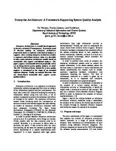
Figure 1. 2D Hilbert curve of the (a) 1 order (b) 2 order (c) 3rd order st
nd
B. Hilbert Space Filling Curve (HC) HC is a geometric fractal composed of base units called cups which can be used for mapping the environment into a single dimensional ID space that can then be used for DHT routing between the nodes. Fig. 1 shows an example of a mapping progression from a two dimensional square to a one dimensional line. In Fig. 1(a), a first order curve composed of a single cup is shown, which progresses to second and third order curves composed of multiple cups as shown in Fig. 1(b) and 1(c) respectively. For each square, the two dimensional points shown in it are mapped sequentially into one dimensional IDs (0, 1, 2, etc., as shown). It can be seen that the subsequent orders of the curve have greater complexity, but also provide a more granular mapping. Space filling curves are constructed in a manner that they pass close to every point in the space they fill. This is particularly useful for distributed camera surveillance applications, as described in section IV. The single
dimensional space is the indexing scheme applied to the curve’s vertices. Given coordinates in the space filled by the curve, the index number of the vertex that is closest to that point is calculated when mapping to the single dimensional space. While there do exist many types of space filling curves, the HC has been proven to have the best locality preserving properties [10]. This means that the mapping of two points in space to the HC will yield indices that approximate the spatial relationship that existed in multiple dimensions. C. MPEG-21 gBSD and H.264 Video As mentioned previously, adapting the video to match the available bandwidth and/or capabilities of the receiver is another important consideration, especially in emergency situations where resources might not be functioning at optimum levels. We propose to perform this adaptation in the compressed-domain. With standard metadata support, complex video processing operations in the compressed domain is straightforward. If the syntax and semantics of the coded sequence are known beforehand, then the cascaded decodingadaptation-(re) encoding steps can be avoided and adaptation can be performed significantly faster [9]. The MPEG-21 generic Bitstream Syntax Description (gBSD) is essentially a metadata definition of the media, written in XML. The MPEG21 gBSD ensures codec independence which means that any MPEG-21 compliant host can adapt videos instantaneously. The H.264 video adaptation system in [9] utilizes MPEG-21 gBSD to help overcome the ordinary adaptation procedure (e.g. cascaded decoding and encoding scheme), saving substantial time for live video adaptation. Certainly, metadata (i.e. gBSD) delivery leads to an additional overhead, but the size of the gBSD is negligible compared to the size of the encoded video. For the video codec itself, we use H.264/AVC, which is the latest video coding and compression standard expected to dominate the field of video codecs due to its advanced compression technique, improved perceptual quality, network friendliness and versatility. The reasons behind choosing H.264 for our framework are its multiple reference pictures for motion compensation and flexible slice sizes. These two features allow us to perform temporal and spatial adaptation in the compressed domain. Moreover, newly commercialized singlechip H.264 encoders and decoders support high quality, high bitrate H.264 video streams (within a LAN, or Enterprise network) to low-resolution, low bit rate video streams over the Internet. IV.
ARCHITECTURE AND DESIGN
A. System Overview As it is not our intention to address all the intricacies involved with the design of a video surveillance system, we take HawkEye [11] as a simple base model, on which our system could be applied. In brief, the features of the HawkEye surveillance system are as follows: cameras employ reference image based event detection; a central server is used to manage the entire system; receivers query the server to receive camera images and for subscribing to event notifications.
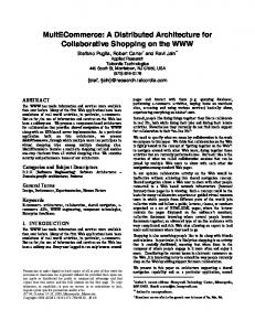
As the HawkEye server has a single point of failure, the entire system is brought down should the server become inaccessible. In addition to this, in a massively distributed camera environment, it is important to efficiently detect a camera at a specific POI. This motivates us to directly allow connections to cameras for lookups and video stream retrieval. In the adapted HawkEye system, both the cameras and the server are connected to a DHT overlay through a wired backbone and having their unique DHT-IDs. The central server maintains its list of active cameras denoted by their DHT-IDs. Fig. 2 illustrates the conceptual relationship between the components of the system. Location lookup is done through the overlay, as highlighted in blue, and the requested video stream is sent directly through the underlying network, as highlighted in red.
Figure 2. System diagram illustrating relationship between the underlying backbone network (green layer), nodes (cameras), overlay (gray layer), wireless receiver (netbook), location lookup (blue) and video streaming (red)
Why DHT?: A DHT is used to accomplish the server’s role of node lookup, but in a distributed fashion and without a central server. The kernel of information that each camera stores to accomplish this is much less than the aggregation stored by the server. Given an emergency situation where the central server and a number of cameras can become disabled, the DHT overlay allows receivers to discover active nodes anywhere nearest to a POI. These receivers can be wirelessly connected to an active camera, using it as an access point to the network and the system. B. Camera considerations 1) Camera Requirements: The availability of IP-security cameras enables us to deploy video surveillance systems in a wide area at a reasonable cost. These cameras, however, also require some processing capabilities as they participate in the overlay network and carry out video adaptation in real time. As illustated in Fig. 2, each camera can communicate locally (wirelessly) with a receiver and globally (wired and/or wireless access to a backbone) to each other within the system. If the camera deployment scheme results in sufficient camera density (i.e. local visibility ranges overlap), then failure of the backbone does not completely disable the system. In this paper, for evaluation purposes, we employ web cameras with low-end (mobile) laptop computers carrying out necessary transmission and adaptation operations.
2) Deployment: Each camera (node) requires preinitialization before its deployment can be completed. The first set of knowledge includes environment size, HC order, and location coordinates. Environment size refers to the range of possible coordinates a camera may be located at. Location coordinates are specified by the user based on building schematics or area specific coordinate systems. Appendix A discusses the methodology for selecting the HC order. In order for a new node to join the overlay, it requires a second piece of knowledge, which is a bootstrap peer for initialization of its routing table; this is required for selforganization of the overlay. Each node must therefore be aware of another node that is connected to the backbone network and part of the overlay. The first node deployed will not be aware of a bootstrap peer and thus starts a new overlay. Any subsequent node will be made aware of its bootstrap by temporarily introducing it to a deployed node over a wireless link. A deployed node, on receiving a bootstrap information request from the new node, will provide its backbone network address (such as IP address and port) over the temporary wireless link. After this information is received, the new node can be plugged into the backbone network and then contact its bootstrap peer to join the overlay. C. Communication Architecture The system communication paradigm is fully distributed to provide fault tolerance. This ensures that no single point of failure can fully cripple the system in an emergency situation. 1) Location lookup: Applying the Hilbert curve for node DHT-ID assignment has the advantage of achieving location lookup. A user can query for a node by specifying the location they wish to stream data from. Mapping the location coordinates to the HC yields the node DHT-ID of the nearest camera at that location. The node DHT-ID is the address of that camera in the overlay, which is used to send out the query. An added benefit is that the coordinates requested by the operator need not be exact in order to reach a node near the specified location. This is due to the fact that DHT-based routing protocols always converge. So a message addressed to a nonexistent node will be delivered to an existing node with the numerically closest DHT-ID, which implies the physically nearest camera.
Figure 3. Range query about a specified central location
2) Range Peer Discovery: Another scenario to consider is the discovery of multiple nodes within a specified range, as illsutrated in Fig. 3. A two step process is applied in order to
achieve this. The first step involves computation of all DHTIDs within the given range. Lawder et al. [14] proposes a range query algorithm for database applications, which we apply here. Once the set DHT-IDs within a spatial range are found, that set is divided into groups of contiguous DHT-IDs. The first DHT-ID in each group is queried through the overlay with a request to provide information on which nodes exist within that group. This task is simplified as every node in the overlay maintains a list of other nodes close to itself in the DHT-ID space. 3) Mobility and Handoff: When the receiver device first enters the environment, it establishes a network link with the system by connecting wirelessly to the first node it discovers. The node acts as the receiver’s proxy to the overlay, as the reciever communicates its requests for location lookups and range peer discovery to the node. Since Wi-Fi networks do not have the continuous handoff capabilities like that of cellular networks, the reciever must continue to discover and wirelessly connect to nodes as it traverses the environment. The decision to connect to a new node is made when the signal strength of the new outweighs the old. When a new wireless connection is made, the reciever must manage handoff of its data streams from the old node connection to the new. D. Video Adaptation In this architecture, a device may request adaptation of the stream or a node may decide to adapt the transmitting stream to meet the bandwidth constraints. Once a proxy node (blue camera in Fig. 2) requests a stream from another node at POI (red camera in Fig. 2), it is sent directly through the underlying network. Each of the nodes can encode video using H.264 codec, which is a realistic assumption these days. While encoding, the node also generates the corresponding metadata of the encoded video in the form of MPEG-21 gBSD. gBSD contains information (e.g. starting byte and length of each frame, slice size, and macroblock information etc.) pertaining to the encoded bitstream. The use of gBSD provides codec independence, and as a result, intermediary nodes or receivers can perform adaptation operations in a fast and format ignorant way. To adapt a video stream, first the gBSD is transformed according to the device or bandwidth requirement, after which adapted bitstream is generated using the transformed gBSD. End user’s preference or device requirement, collected using the MPEG-21 Usage Environment Description (UED) tool, is the input to the transformation decision-making mechanism. This allows the video to be adapted on the fly, and not just for a predefined and limited list of supported devices. To generate the transformed gBSD, some tools (e.g. XSLT [15]) require complete XML description to be loaded first. Therefore, in each node, live video streams are processed as small clips (e.g. 1-second clip at 20frames per second). To accommodate peer mobility and bandwidth fluctuation, a new adaptation rate can be applied to the next video clip. For temporal adaptation, the multiple reference frame feature of H.264 video is exploited. In gBSD, frame importance level is set based on the following – 1. Reference frame, 2. Motion in the frame, 3. Frame size. The start of each
For spatial adaptation, the video frame slices are encoded in fixed size and in a self-contained manner. The offsets of the slices in the encoded frames are also written in the gBSD during the encoding process. The macroblocks within a selfcontained slice will not refer to any macroblock belonging to other slices. This will result in fewer choices for prediction for the macroblocks along the edge of the slice for cropping a frame to achieve a target resolution. Similar to frame rate adaptation, spatial adaptation is performed by discarding some portions of the encoded frames to achieve the target resolution. To extract the desired region from the compressed video, offsets of the slices are first parsed from the gBSD. Once the slices have been extracted, the video/frame headers are updated accordingly by setting size of the region. E. Adaptation Decision Making The video adaptation process is computationally intensive, as shown in Section 5, and the computing power available in the nodes is a limited resource. Therefore, if a node is adapting and streaming video for a given target quality, the node will be able to fulfill requests from other receivers desiring the same output stream (given available wireless communication resources). However, a request for a video stream of different quality from what is currently being generated would overload the node. While this issue can be resolved with the addition of hardware to increase computing power, this is not a costscalable solution. Addition of intelligent decision making partially alleviates this system bottleneck. If a node receives a single request for a target output, that node can simply capture video at that frame rate. If a second request is made to the node, the higher video requirement of the two requests is selected as the frame rate video is captured at; the lower target request is fulfilled through adaptation of the captured video. V.
EVALUATION
In this section, we present the performance of our proposed scheme. The experimental results include both the aspects of our scheme covering video adaptation and overlay. For overlay, our results are collected over a simulated network. A. Network Overlay Analysis By adapting the Pastry design to incorporate location sensitive DHT-IDs, we are able to achieve location lookup in the distributed system. The impact of this regarding overlay performance must be taken into account. Assuming a network consisting of N nodes, in the worst case, the expected number of forwarding hops to deliver a messages to a random DHT-ID is log (in our simulation, we set the configuration
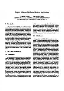
parameter b to its default value of 4). Upon a node failure, the messages. network is restored by the exchange of log For our experimentation, we consider an environment of a quarter sq. km, with average building height of 20 meters, with a random distribution of 2500 cameras. This environment was simulated with the open source FreePastry [17] implementation, with and without the addition of the HC based DHT-IDs. A HC of the 5th order was used for DHT-ID generation, and it was chosen according to the reasoning discussed in Appendix A. 0.5 Original Pastry Adapted Pastry
0.45 0.4 0.35
Probability
frame in the compressed bitstream, the length of each encoded frame and the Network Abstraction Layer (NAL) units are written in the gBSD. The encoded bitstream is adapted for different frame rates by discarding fames based on the frame importance level. Frames used as a reference frame, or with high motion, have the higher priority than other frames. Otherwise, frames with low priority or equal priority are dropped randomly based on the total size of the discarded frames to achieve a low bit rate.
0.3 0.25 0.2 0.15 0.1 0.05 0
1
2
3
4 5 Hop Count
6
7
8
Figure 4. Probability Distribution Function of Hop Count
It can be seen from Fig. 4 that the adapted overlay, in addition to providing built-in location lookup, out performs the original overlay implementation in scenarios where cameras in immediate surroundings need to be accessed with minimum latency. This is particularly very important when emergency officials need to access the video stream from nearby cameras. Therefore, we can conclude that a modified Pastry design fulfills our requirements for an efficient lookup mechanism. B. Real time adaptation performance To generate gBSD, we have enhanced the ITU-T H.264 video reference software implementation [16] with gBSD generation functionality. In the H.264 encoder configuration, we set the following parameters - Profile: Main, Period of Iframes: 9, Quantization parameter: 28, search range: 8, number of reference frames: 8. Considering the fact that nodes will be equipped with low processing power, we have used Logitech Quickcam connected to Pentium-III laptops to evaluate the adaptation performance. For bit rate calculations, a frame size of 5 kilobytes (KB) is assumed, regardless of the motion in the video. TABLE I.
GBSD-BASED LIVE TEMPORAL ADAPTATION PERFORMANCE
Machine Specification
Captured Video
Pentium III 700 Mhz 256MB RAM
CIF (352 × 288) 20 fps
Target Video Requirement 1 - 5 fps 6 - 10 fps 11 - 15 fps 16 – 19 fps
Adaptation Time (ms) 160 190 235 280
Table I presents the average time to adapt 1-second video clips for temporal adaptation. The target video requirements vary from 1 to 19 frames per second (fps) in aggregated steps. The adaptation time increases as the frame rate increase; this is due to the fact that the adaptation engine must compute a greater number of inter-frame dependencies in the adapted video. Table II presents the average time to adapt the CIF resolution video clips to QCIF and SQCIF resolutions. Spatial adaptation of the video data requires greater adaptation time due to the greater effort required to analyze macroblocks within the compressed frames. Again, the adaptation time required is dependent on the quality of the output video. To skip spatial adaptation, a node may capture frames in a pre-determined resolution. TABLE II.
source and adapts video for other receivers that connect to it. We are now investigating the soft hand-off issue using ordinary transmission protocols for wireless LANs, and mapping a wide physical area into the application architecture for the ease of querying and discovering a node at a distant point-of-interest, as well as real-time compressed-domain video authentication. REFERENCES [1]
BBC News, “Mumbai rocked by deadly attacks”, November 2008. [Online]. Available: http://news.bbc.co.uk/2/hi/south_asia/7751160.stm [Last Accessed: June 23, 2009]
[2]
Z. Zhang, S. Kurtev, “Independent motion detection directly from compressed surveillance video”, in Proceedings of ACM International Workshop on Video Surveillance, 2003.
[3]
E. Keogh et al., “A Novel Technique for Indexing Video Surveillance Data”, in Proceedings of ACM International Workshop on Video Surveillance, 2003.
[4]
S.Y. Hu, J. F. Chen and T. H. Chen, "VON: A Scalable Peer-to-Peer Network for Virtual Environments," IEEE Network, vol. 20, no. 4, Jul./Aug. 2006, pp. 22-31.
[5]
A. Rowstron and P. Druschel, "Pastry: Scalable, distributed object location and routing for large-scale peer-to-peer systems". IFIP/ACM International Conference on Distributed Systems Platforms (Middleware), Heidelberg, Germany, pages 329-350, November, 2001.
[6]
R. Rejaie, A. Ortega, “PALS: Peer-to-Peer Adaptive Layered Streaming”, in Proceedings of ACM Workshop on Network and Operating System Support for Digital Audio and Video, pp. 153 – 161, 2003.
[7]
X. Xiaofeng et al. “A peer-to-peer video-on-demand system using multiple description coding and server diversity", in Proceedings of IEEE International Conference on Image Processing, pp. 1759-1762, 2004.
[8]
C. Feng, B. Li, "On Large-Scale Peer-to-Peer Streaming Systems with Network Coding", in Proceedings of ACM Multimedia, pp. 269-278, 2008.
[9]
R. Iqbal, S. Shirmohammadi, A. El Saddik, and J. Zhao, “Compressed Domain Video Processing for Adaptation, Encryption, and Authentication”, IEEE MultiMedia, 2008.
GBSD-BASED LIVE SPATIAL ADAPTATION PERFORMANCE
Machine Specification
Captured Video
Pentium III 700 Mhz 256MB RAM
CIF (352 × 288) 20 fps
Target Video Requirement QCIF (176 × 144) SQCIF (128 × 96)
Adaptation Time (ms) 370 275
From the table data, we can claim that the adaptation time is quite acceptable considering the fact that the processing is performed in the compressed domain and in a live fashion. On average, for each adaptation operation CPU usage varies from 45% - 55%. The factors that influence the CPU usage during the adaptation are the level of detail of the gBSD and motion in the frame. If we consider temporal adaptation only then the size of the gBSD is only 2-5% of the encoded bitstream. VI.
DISCUSSION
Due to initial negotiation between receiver and proxy node, and complex video encoding operations, video streams experience a one to two second startup delay. The delay experienced by the user between the live capture and its viewing is the aggregate of the real-time adaptation delay, network transmission delay, and time for receiver side rendering. Additionally, one may ask how the camera location coordinates can be obtained automatically. While the Global Positioning System (GPS) is a candidate, it is ineffective for 3D positioning and requires a clear line of sight to the orbiting satellites for optimal results. Other issues related to video surveillance and security services are assumed to be part of the deployed system and outside the scope of this research due to their existing implementations. Examples of these include authentication of receivers to the distributed system, receiver profile sharing among nodes, as well as collation, aggregation, and indexing of video data in a repository. VII. CONCLUSION In this paper, we proposed a distributed camera network architecture supporting video adaptation. This architecture is fully distributed and it is able to operate partially in case of node or underlying infrastructure failures. It is a lightweight design where core operations are simple to implement and easy to deploy. The system also supports the concept of adaptive P2P streaming where a receiving node may become the stream
[10] M. Knoll, T. Weis, “Optimizing Locality for Self-organizing ContextBased Systems”, Springer LNCS, vol. 4124, pp. 62—73, 2006. [11] M. Farrell et al, “Rapidly Deployable Distributed Video Surveillance System for Resource Constrained Applications”, in Proceedings of IEEE Systems and Information Engineering Design Symposium, 2007. [12] T. Bially, “Space-Filling Curves: Their Generation and Their Application to Bandwidth Reduction”, IEEE Transactions on Information Theory, IT-15(6):658-664, 1969. [13] A.R. Butz, “Alternative Algorithm for Hilbert's Space-Filling Curve”, IEEE Transactions on Computers, Vol. 20, Issue 4, 1971. [14] J. Lawder, “The Application of Space-Filling Curves to the Storage and Retrieval of Multi-dimensional Data”, Ph.D. Thesis, Birkbeck College, University of London, 1999. [15] J. Clark, “XSL Transformations (XSLT)”, November 1999. [Online]. Available: http://www.w3.org/TR/xslt [Last Accessed: June 23, 2009]. [16] [Online]. Available: http://wftp3.itu.int/av-arch/jvtsite/reference_software/ [Last Accessed: June 23, 2009] [17] “FreePastry”. [Online]. Available: http://freepastry.org/FreePastry [Last Accessed: June 23, 2009]
APPENDIX A The first and most fundamental factor in choosing an appropriate curve order is the number of nodes that the system will include. As vertex indices from the curve become DHT-
IDs, the number of vertices acts as the upper limit of the potential number of nodes the system can accommodate. Thus, the curve order chosen must produce a sufficient number of vertices. (1)
2
Equation 1 states V, the number of vertices in the curve, is determined by a curve order k and number of dimensions M. /
2
(2)
Equation 2 states the minimum value of the curve order required to have a sufficient amount of vertices to accommodate N, the number of potential nodes to participate in the system. In real world application scenarios, the number of dimensions spanned by the curve would likely be no more than three. Two dimensions may be used in scenarios when floors on a building each have their own communication architecture. The second factor in choosing an appropriate curve order is having the vertex density of the curve be on par with the distribution of the nodes in the environment. If nodes are clustered in the environment, a higher order curve may be necessary as the traditional Hilbert curve's vertex coordinates are evenly distributed in each of its dimensions.
/ 2
(3)
1
Equation 3 states delta, the distance between vertices in a dimension given a curve order k and the distance the dimension spans d. This analysis assumes that the HC is constructed such that it spans the entirety of all dimensions. /
1 /
2
(4)
Equation 4 states the minimum curve order such that the smallest distance between nodes in a single dimension is greater than the distance between vertices in the curve. max
,
(5)
In order to ensure that requirements from both factors are satisfied, the maximum of the calculated minimum curve orders should be chosen, as stated in Equation 5. This curve order satisfies the above requirements, but higher values may be selected for the system. Higher order curves provides a greater number of vertices for use as DHTIDs, but their use must be balanced against the complexity increase they incur, especially in resource limited scenarios. Care must be taken that the maximum DHT-ID value can be represented by the data types implemented used by the calculation systems without overflows occurring.