Computer Communications 26 (2003) 1782–1791 www.elsevier.com/locate/comcom
A distributed simulator for network resource management investigation Josep L. Marzo*, Pere Vila`, Lluı´s Fa`brega, Daniel Massaguer Institut d’Informa`tica i Aplicacions (IIiA), Universitat de Girona, Lluis Santalo´ Av., 17071 Girona, Spain
Abstract Network resource management deals with protocols and networks capable of performing a reservation of the available resources in order to guarantee a certain Quality of Service (QoS). Examples of these technologies are Asynchronous Transfer Mode (ATM) and Multi-Protocol Label Switching (MPLS), which are usually used in core networks. An important objective of network providers is to obtain the maximum profit from their resources; hence there is a need for an efficient resource management. Investigation in this field is difficult, mainly because network research laboratories do not have a large core network where they can investigate their approaches and algorithms. This paper presents a simple but flexible distributed simulator that supports a wide range of different experiments. It is based on an event-oriented simulation at a connection level (no packet or cell granularity). The distributed simulator is oriented to the simulation of large core networks and support different routing and admission control algorithms. The simulator must also support the development of different resource management architectures: centralised, distributed, hybrid, based on artificial intelligence techniques, etc. The paper also presents the scenario where this simulator can be used, mainly in the context of Traffic Engineering, i.e. dynamic bandwidth management and fast restoration mechanisms. Examples of different management applications and experiments performed using the simulator are presented. q 2003 Elsevier B.V. All rights reserved. Keywords: Distributed simulation; Client/server network management and control; Multi-Protocol Label Switching; Asynchronous Transfer Mode
1. Introduction Although the technology of the present-day networks offers users increasing transmission capacity, the fact is that the increase in the amount of data to be transmitted is higher than the network capacity. This is due to the high increase in the number of new users and the appearance of new services (multimedia and interactive resource-consuming services). Therefore, it is clearly necessary to use network resources efficiently. Large telecommunication companies have been using powerful network management tools, usually based on standards, which provide network statistics and analysis tools to help human network managers in decision-making. These centralised decision-making could suffer a scalability problem when excessive network monitoring traffic arises. Moreover, these tools are designed to perform manual * Corresponding author. Tel.: þ 34-972-418497; fax: þ 34-972-418098. E-mail addresses:
[email protected] (J.L. Marzo),
[email protected] (P. Vila`),
[email protected] (L. Fa`brega),
[email protected] (D. Massaguer). 0140-3664/03/$ - see front matter q 2003 Elsevier B.V. All rights reserved. doi:10.1016/S0140-3664(03)00051-3
network management or, at the most, to carry out some actions at pre-set hours of the day. By using certain network management technologies the network adapts itself automatically under different levels of load in a dynamic way. Generally network management encompasses a broad range of tasks that are summarised in the so-called FCAPS (Fault, Configuration, Accounting, Performance, and Security) management areas. The field of resource management deals mainly with Performance and Fault management, and more specifically with dynamic bandwidth management and fault protection mechanisms [1,2]. This paper presents a distributed simulator to investigate network resource management. Simulation is a crucial tool in the investigation and evaluation of different mechanisms or techniques to perform this resource management. The investigation is focused on automatic tools, several of which are partially or totally distributed. The simulator itself is also distributed in order to facilitate the development and testing of these mechanisms. Section 2 presents the background and the environment where these resource management techniques can be
J.L. Marzo et al. / Computer Communications 26 (2003) 1782–1791
applied and details the main idea to perform this management, i.e. the logical network. It also introduces two network technologies that have mechanisms to establish and manage a logical network. Section 3 focuses on what are the specific actions that must be carried out by network resource management (i.e. fault protection and dynamic bandwidth management) and that the distributed simulator must support. Section 4 presents some related work, gives references to other simulation tools and points out the main differences with our proposal. Section 5 details the simulator design and its main characteristics. Section 6 presents several simulation scenarios for the evaluation of the simulator behaviour, using different management applications that we have developed. Finally, Section 7 presents the conclusions and future work.
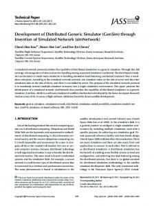
2. Background There are several types of network technologies that are able to dynamically manage their resources. This capability allows the design and implementation of automatic mechanisms to manage network resources. Usually the main resource that must be managed is the bandwidth; this requires the network technology to have some kind of hierarchical reservation mechanism, i.e. the ability to establish a logical network layer over the physical network. Then, the user connections are established through the paths of this logical network. The concept of a logical network (or a logical topology) is presented in Fig. 1. The logical paths can be seen as pre-reservations of bandwidth between different nodes in order to facilitate the establishment of user connections or flows. The logical network can be dynamically changed and this implies that the network resources can be adapted to the traffic demand to obtain the maximum performance (and profit) from the available physical resources. The logical network can also be used to implement protection mechanisms, i.e. some of the logical paths can be established not to be used as working paths for the traffic demand but as a backup or protection paths in case of failure. These mechanisms can be included in Traffic Engineering (TE) and they are detailed in Section 3. The following
Fig. 1. Example of a logical network established with the logical paths a, b, c, etc.
1783
subsections briefly describe two network technologies that make use of these hierarchical reservation mechanisms: MPLS and ATM. An example of an environment where to apply these mechanisms is presented in Ref. [3]. 2.1. Multi-protocol label switching (MPLS) MPLS is a network architecture that enables management mechanisms for the core network belonging to a network provider, usually in an Internet environment. MPLS groups user flows into aggregates and allows the allocation of a certain capacity to each aggregate [4,5]. The routers belonging to an MPLS domain are called Label Switched Routers (LSR). When a data packet comes into an MPLS domain through an ingress LSR, the packet is classified into a specific Forwarding Equivalent Class (FEC), which groups the packets with certain common properties (protocol, size, origin, destination, etc.). The packets inside an MPLS domain go through preestablished paths called Label Switched Paths (LSP). The set of LSPs constitutes the logical network and it is established using a signalling protocol called Label Distribution Protocol (LDP) [6]. An example of an MPLS domain is depicted in Fig. 2. 2.2. Asynchronous transfer mode (ATM) ATM networks are designed to support a wide range of services of diverse characteristics [7,8]. They have two layers of hierarchy: Virtual Path (VP) and Virtual Channel (VC). Users can establish and release connections, i.e. VCs, through pre-established VPs. The VP layer is used to simplify the establishment of new connections and it also constitutes a logical network. This allows the network to carry out dynamic management of this logical topology and enables its adaptation to improve network resource utilisation [9,10]. 2.3. Logical paths This paper focuses on the idea of logical or virtual network, i.e. a dynamically configurable network (see
Fig. 2. Example of an MPLS domain and its operation.
1784
J.L. Marzo et al. / Computer Communications 26 (2003) 1782–1791
Fig. 1). Connections or flows are established through this set of VPs in ATM, or LSPs in MPLS. In this paper we use both terms VP and LSP in specific examples, or the generic term Logical Path (LP) to refer to any kind of logical path regardless of the network technology.
3. Network resource management experimentation This section presents the main mechanisms performed by the network resource management. Usually these mechanisms act on a periodical basis, e.g. every hour. There are also restoration techniques that must re-route the links affected by a failure as fast as possible. Therefore, there are also temporal considerations since some mechanisms act in a short term, others in a mid-term and others in a long term. This time scale idea is depicted in Fig. 3. The three main resource management functions supported by our distributed simulator are dynamic bandwidth management, fault protection and spare capacity planning. These functions are briefly described in Sections 3.1– 3.3.
Fig. 4. Bandwidth management.
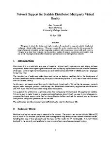
3.1. Dynamic bandwidth management Bandwidth management attempts to manage the capacities assigned to the different logical paths. Parts of the network can become under-utilised, and other parts congested. When this occurs, some connections are rejected which could be accepted if the traffic loads were better balanced.
One of the main objectives of bandwidth management is to minimise Call Blocking Probability (CBP), i.e. the probability that an offered call is rejected due to insufficient capacity being available for the allocation of the new call. Two actions are usually performed for the bandwidth management system: bandwidth re-allocation and logical path re-routing [9,10]. There are four typical cases, which are shown in Fig. 4. (a) If there is enough spare bandwidth in the link, then the congested LP is expanded using this bandwidth. (b) If there is not enough spare bandwidth and other LPs going through the same link are under-utilised, it is possible to transfer resources from one LP to the other. If (a) and (b) fail, then a re-routing is needed: (c) If the congested LP finds another path with enough resources then it can be re-routed. Otherwise, (d) other LPs may be re-routed through other links in order to free enough capacity to expand the congested LP. 3.2. Fault protection
Fig. 3. Network resource management operations.
The ultimate goal of the protection mechanisms is that customers do not notice failures. To achieve this fast restoration, pre-planned schemes based on backup paths are used [11,12]. However, there are several types of backup schemes (see Fig. 5), each one better than the others in particular situations. For this reason, and in order to minimise the required resources for the backup paths, many proposals make use of several of these schemes at the same time in an hybrid approach [13]. This adds yet more complexity to the management system.
J.L. Marzo et al. / Computer Communications 26 (2003) 1782–1791
1785
The distributed simulator allows researchers to implement different resource management techniques regardless of whether they are centralised and/or distributed algorithms. The simulator even allows the development of non-automatic resource management tools, i.e. manual utilities to manage the resources of the simulated network.
4. Related work
Fig. 5. Different backup mechanisms. (a) Global. (b) Local. (c) Reverse. (d) Hybrid-schemes.
3.3. Spare capacity planning Network providers want high revenues. Since bandwidth is an expensive resource, the objective is to minimize the bandwidth reserved for restoration procedures [14]. In other words, a good spare-capacity planning is essential. The main goal of hybrid restoration mechanisms is to save up spare capacity. It is necessary to establish the desired network protection level, i.e. protect the network against one simultaneous link or node failure. In such a scenario, there is the technique of sharing bandwidth between different backup paths (see Fig. 6). 3.4. Interrelation of these techniques Most of the above resource management techniques can be applied to different kinds of network technologies that have resource management mechanisms like the ones detailed in the previous section. These techniques are usually implemented using distributed and/or centralised algorithms, and sometimes a proposed system implements several of these techniques at the same time. All these techniques modify the logical path network, so they are very interrelated. For this reason there are several proposed methods that try to deal with all these techniques simultaneously, but this usually implies a high degree of complexity. To cope with this complexity there are many proposals for network resource management based on Distributed Artificial Intelligence (DAI) techniques, i.e. multi-agent systems (MAS). Examples of distributed techniques are [15,16], and examples of DAI based techniques are [17,18].
There is a significant number of network simulators. Most of them are general purpose network simulators that include hundreds of modules. These modules allow the users to simulate complex networks using different technologies (wireless, LANs, satellite, etc). Usually these simulators also have large libraries with models of real network equipment, implemented protocols, and other. They also give to the user the ability to develop its own modules or even to modify the original ones. This huge flexibility along with the number of modules and libraries make long and difficult their learning for beginners. These are typically event oriented simulators at a packet level. Examples of this type of simulators are OPNET1 and NS-22. Both simulators where selected in the TEQUILA project3. NS-2 was selected to test aspects of TE algorithms in the context intra-domain environments and OPNET was selected to test inter-domain aspects. In Ref. [19] the fluid simulation is compared to the packet-level simulation. In the fluid simulation paradigm, network traffic is modelled in terms of continuous fluid flow, rather than discrete packet instances. Our proposal is more similar to the fluid simulation paradigm than to the packetlevel simulation. This represents a higher level of abstraction. The simulation tool presented in this paper is also more oriented to help developing new management tools. In this sense it is similar to tools like MIMIC4 and ALPINE5. The first one is based on the simulation of SNMP Agents and it is also oriented to the development and testing of network management applications. ALPINE is based on the placement of the networking stack outside the operating system kernel in order to help the developing and modification of protocols. In this case it is not a simulator because it makes use of the real network.
5. Simulator design and implementation The distributed simulator design is based on a client/server model. A previous version can be found in 1 2 3
Fig. 6. Spare Capacity optimization by sharing the bandwidth between backup paths.
4 5
OPNET URL: http://www.opnet.com NS-2 URL: http://www.isi.edu/nsnam/ns TEQUILA URL: http://www.ist-tequila.org MIMIC URL: http://www.gambitcomm.com ALPINE URL: http://alpine.cs.washington.edu
1786
J.L. Marzo et al. / Computer Communications 26 (2003) 1782–1791
Ref. [20]. The server process is called Node Emulator (NE) and its main function is the emulation of a working network node. This NE process offers a high functionality to its clients, which can be of two different types. The first type of client process is the Traffic Event Generator (TEG), that can be attached to an NE and acts as a pool of users asking connections or flows to a destination node. The TEG and NE sets of processes constitute the distributed simulator where resource management investigation is performed. The second type of client processes is the network resource management algorithms. TEG and management client processes, access to the server (NE) functionality through its Application Programming Interface (API). This API offers a set of functions to perform the node management, and allow the checking and modification of the node internal status. The API also has several TEG-oriented functions, which are detailed later. Performing a network simulation with a certain number of nodes implies the use of the same number of NE server processes, which can be in the same or in different computers. This is due to the use these processes make of the TCP/IP socket interface. Both the NE and TEG processes are implemented in Cþ þ and can be executed in a Sun workstation under Sun Solaris OS, as well as in a PC under Linux OS. Network resource management algorithms also have to be implemented as client processes. Thus it is possible to implement a centralised resource management algorithm or a distributed one, as it is shown in Fig. 7. Generally there is no communication among NE processes unless a specific routing protocol is implemented. The default routing protocol takes into account the direct path only. However, the default routing and admission control protocols can be changed through the modification of the NE source code. These changes are relatively easy to do due to the modular object oriented simulator design, and its clear documentation.
The TEG processes are able to send events to the NE processes. The defined events include ‘connection-demand’ and ‘connection-release’, to establish new connections or flows and to release existing ones, respectively. The generation of these events follows a parameterized distribution, e.g. a negative exponential distribution, thus the traffic load is independently configurable for every node. Moreover it is possible to attach more than one TEG process to the same NE. There are three additional types of events which can be generated by the TEG process. The first one is called ‘Instantaneous-BW’ and for every established connection or flow, during its life span, the TEG process can generate this type of events to inform the NE of the real bandwidth used in that connection or flow. This type of events can also follow several different parameterised distributions. The second and third events are the ‘Link-failed-notice’ and the ‘Link-restored-notice’, and they are used to inform an NE process to mark a physical link as failed or as a working link again. This is used to simulate link failures on the physical network. There is also a mechanism in the NE processes to send an alarm notification to the network resource management processes in case a link is marked as a failed link. The different TEG processes are independent and all of them can be configured with different parameters. The TEG processes are not only used for the connection/flow distribution and connection/flow duration, but also to generate the different quality of service requested on each connection/flow and the selection of the destination node. These characteristics can also be set to configure, for example, a TEG to generate only one type of connection/flow with one specific destination node. The simulated physical network is static and cannot change during the simulation. Moreover, all the NE processes read the physical network structure from the same configuration file. It is possible to set up an initial logical path network in the same common configuration file.
Fig. 7. Distribution of client and server processes. (A) Centralised management case. (B) Distributed management case.
J.L. Marzo et al. / Computer Communications 26 (2003) 1782–1791
If there is no kind of network resource management, the logical path network also remains static. The network resource management algorithms are not part of the simulation platform; they can be developed in any language on any platform and can be executed on the same or different computers from where the simulation processes are being executed. As it can be deduced, if the network resource management is implemented as a distributed algorithm, the communication among the management processes can use mechanisms or technologies different from the TCP/IP socket interface, e.g. CORBA6 or Java RMI7, allowing the implementation of many different types of management applications. Every NE process generates a log file with all the functions and parameters that have been requested by the TEG(s) processes and/or the management process attached to it. From the analysis of this set of log files it is possible to extract the results and even to reproduce the complete simulation. These log files are based on formatted text and they can also be directly loaded into spreadsheet programs or statistic packets. An important characteristic is the simulator scalability in terms of the number of nodes that can be simulated. The simulation processes can be distributed in several computers and moreover they are executed in parallel. The main constrain is the client – server communication, but the use of an isolated network (e.g. 100 Mbps Ethernet) allows the achievement of a relatively high performance. For instance, if the TEG clients are strategically placed in the same computers than the NE processes they are attached to, and then there is no communication between the computers (with the default CAC and routing configuration). In this case, the only process communication comes from the network management algorithm being tested or developed. Therefore, in such case the scalability do not depend on the simulator but on the management system.
6. Simulation examples
1787
Fig. 8. Four-node network with the established LSPs.
tested. This distributed algorithm monitors the LSPs on every node. More specifically, there is a management process that monitors the LSPs that begin on a given node and calculate the CBP, i.e. the probability of a flow being rejected in the ingress LSR, for every LSP. If a certain CBP threshold is achieved, then the dynamic management process on that node asks the other involved nodes for bandwidth re-allocation, or if it is not possible, for LSP rerouting. The necessary information is sent to other nodes by means of a developed application protocol. In this specific example the dynamic management and the monitoring processes were implemented using Java and interacted with the simulated nodes using their API (a Java package implementing an easy-to-use communication interface between an NE process and a Java application was also developed). The structure is presented in Fig. 9. The distributed algorithm tested bases the decision of performing a logical network reconfiguration using only information that the node has locally. Moreover, no management process performs a reconfiguration of the whole logical network; each management process at each node only manages the resources on that node. Of course,
This section presents simple scenarios to show how the simulator works and the different type of applications that can be performed using it. In some cases they are just demonstration examples, and in other cases they are part of our ongoing research. 6.1. Dynamic bandwidth management This section describes a dynamic bandwidth management experiment in an MPLS domain. The scenario presents a simple four-node network, where several LSPs are established as is shown in Fig. 8. In this example, a distributed algorithm based only on local information is 6 7
CORBA URL: http://www.corba.org Java URL: http://java.sun.com
Fig. 9. The different processes involved in the simulation example and the communication between them. On every Management process there are several threads each one monitoring an LSP.
1788
J.L. Marzo et al. / Computer Communications 26 (2003) 1782–1791
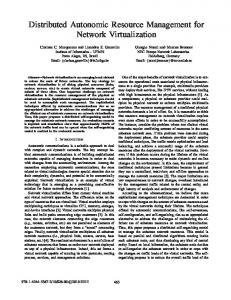
Fig. 10. LSP network changes due to the bandwidth management mechanisms.
once the decision is made, the management process on that node must co-ordinate the changes with the rest of the affected nodes. Fig. 10 shows the three different network situations in the course of the simulation. The main idea of this example experiment is that the flow demand from node 1 to node 2, which makes use of the LSP1, constantly increases. This means that an LSP reconfiguration will be required to adapt the logical network topology to the new demand. First of all, the management processes try to expand the bandwidth assigned to an LSP without changing the logical network topology. This can be achieved using free bandwidth from the link and/or reducing the bandwidth of other LSPs that are not full. In this particular experiment this action is performed for the first time when a CBP of 70% is reached on LSP1. After that, more flows can be accepted in LSP1, but as the user demand keeps increasing, once again a CBP of 70% for LSP1 is reached. In this case there is no more free bandwidth in link 1, and the management process decides to change the LSP2 and re-route it through node 4 instead of through node 2. Therefore, free bandwidth is released in link 1 and LSP1 capacity can be expanded to the maximum capacity of the link.
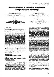
This simple experiment shows how the management process at node 1 adapts the logical network in order to accept more flows from node 1 to node 2. Doing this dynamic resource management means that a better network performance is achieved, i.e. the same resources are better utilised. Without this resource management, in a static logical network scenario, more flows would have been rejected. Fig. 11 also displays a graph including the LSP1 load, i.e. number of connections (left y-axis), and the LSP1 CBP (right y-axis) versus time. Note that the demanded flows are homogeneous (2 Mbps each) so before the first change, LSP1 can accept a maximum of 6 connections (LSP1 ¼ 12 Mbps). Between the first and second change, LSP1 can accept 9 connections (LSP1 ¼ 18 Mbps) and after the second change it can accept 15 connections (LSP1 ¼ 30 Mbps). The LSP1 bandwidth changes are made when the CBP reaches 70% in this particular experiment. 6.2. Evaluating a function to detect congestion The experiments presented here were carried out in order to evaluate different mechanisms for the identification of
Fig. 11. Load and CBP versus time for the LSP 1.
J.L. Marzo et al. / Computer Communications 26 (2003) 1782–1791
congested logical paths. An interesting problem is how to find out if an LP is congested. Each node has a monitoring agent (or M-Agent), that periodically performs a monitoring function over a single logical path (a time interval of 10 s for these experiments) and it decides whether the LP is congested or not. If the LP is considered to be congested, then the M-Agent triggers the mechanism for increasing the bandwidth of the LP by taking spare resources from the link. If this is not possible, the system tries to allocate unused resources that are already assigned to other LPs (using a pre-emptive policy). In the proposed scenario the management system do not utilize the LP re-routing functions for reasons of clarity and only the bandwidth re-allocation is used. In this case the management system was build as a distributed system based on a MAS. We also use Java for the management system, and the communication among the agents was through RMI as in the previous example. The triggering mechanism is called ‘Trigger Function’ and we have evaluated three different functions: (a) Rejected-5: If the 5 last consecutive connection or flow requests for a given LP are rejected, the LP is congested. (b) CBP-70: The CBP is calculated using the last 30 connection or flow requests. If the CBP is greater or equal to 70%, the LP is congested. (c) Load-90: If the load of the LP is greater or equal to 90% of its capacity, then it is congested. The simulated network for the experiments had 4 nodes and a similar configuration that the previous example. Each physical link had 100 Mbps of capacity. There were 10 unidirectional LPs with an initially assigned capacity of 15 Mbps. All LPs had the same offered traffic load (specified in Table 1). Using negative exponential distributions for the interarrival time and duration, the mean load for each LP is 100 Mbps, hence all links tend to be congested. The amount of bandwidth by which to increase an LP every time the Trigger function detects congestion was fixed to 2 Mbps. The simulation time was 1 h in each case and the general behavior, shown in Fig. 12, was as follows: In the case of a single LP per link, this LP
1789
Fig. 12. Capacities assigned to LPs beginning in node 1 (LPs 1, 2, and 3), using the Trigger function Reject-5 and every change of bandwidth is of 2 Mbps.
increased its bandwidth up to near the maximum level of the link (LP 3 in Fig. 12). In the case of two LPs per link they increased their bandwidth until they reached half of the link capacity and then they competed for bandwidth (LPs 1 and 2 in Fig. 12). The results comparing the three trigger functions show significant differences. It is possible to find more details in [21], where this specific experiment was presented. 6.3. Using a centralised monitoring application In this case we developed a centralized management application, in order to test the possibilities of the simulated network. This management application polls periodically all the nodes in the network asking for their complete data. Thus, this application allows visualizing the load of every link and every LP in the network. Moreover, this application also allows the modification of the logical network manually, i.e. establish and release LPs and change their capacities. This application was built using the ATM terminology as a graphical utility. Fig. 13 shows a window capture
Table 1 Traffic offered for each LP Traffic class Assigned bandwidth Mean interarrival Mean duration(s) time(s) 1 2 3 4 5
64 Kbps 2 Mbps 2 Mbps 4 Mbps 10 Mbps
2 10 20 30 100
60 120 300 120 300
Fig. 13. Window capture showing the managed physical network and a monitoring window for one link.
1790
J.L. Marzo et al. / Computer Communications 26 (2003) 1782–1791
The faults are not simultaneous and the first to occur is the link 6 – 7 (not the 7 –6). Node 6 detects the fault (NE 6 sends the alarm to the management application) and sends alarm messages to every edge node that has an LP going through link 6– 7 (all this happens at the management application level). Then the edge links send messages along the backup LPs to capture the required bandwidth and switch the established connections from the original LPs to the backup ones. When the fault is corrected, and the link 6– 7 is working again, there is a similar mechanism that moves back the connections to the original LPs.
7. Conclusions and future work Fig. 14. Simulated network. Only the 5 edge nodes (1– 5) had an associated TEG process.
displaying the physical network topology and monitoring a physical link. Again this centralized management application was build using Java and it maintains open communication sockets with all the nodes of the simulated network. Fig. 14 shows the simulated network for this experiment, which had 9 nodes and 16 physical links. 6.4. Implementation of a pre-planned restoration mechanism This example shows a simple experiment where we have implemented a pre-planned restoration mechanism. This mechanism detects the fault alarms generated by the nodes, and switches the established connections from the affected LPs to their corresponding backup LP. This example was also utilised to perform the simulation distributing the processes into three different computers. Fig. 15 presents the simulated network. There are 30 nodes (10 on each computer) of whom 10 represent edge nodes. There are 50 established LPs connecting every edge node from the left side (A – E) to all the nodes on the right side (F– J) and vice versa. There are also 50 backup LPs protecting the working ones, which utilise a global scheme. The original size of the backup LPs is zero.
This study has presented a distributed simulation platform able to perform a wide range of experiments related to network resource management. There is a large amount of network simulation platforms, but the one this paper presents has demonstrate its versatility and scalability while maintaining its simplicity and ease of use. This simulator tool is designed to test and develop network resource management applications. The initial objective of designing a very flexible and configurable platform, while at the same time maintaining its modularity, was also achieved by the use of client/server architecture. At present, the simulation processes have been fully tested and are operative, and we plan to use it for a lot of experiments related to the research being carried out in our group. We are now developing several other network resource management mechanisms to be tested using the distributed simulator. These algorithms allow us to find possible bugs and also introduce new functionality in the simulator. As a future work on the distributed simulator itself there are three defined lines to follow. First of all we plan to develop a visual tool to make the network topology definition easier and automate the generation of the configuration files and the distribution of the simulation processes over several machines and the starting of a simulation. Second, we plan the development of an automatic tool to process the log files generated for every node. This tool could perform the merge of the several log files and generate statistics and extract complex results. Finally these log files could also be used to perform a debug task of network management mechanisms and even debug the simulator itself. This last point is a long-term idea but we think it could be interesting to transform a simulation tool into a debugging tool for network management algorithms.
Acknowledgements
Fig. 15. Simulated network for the restoration test. Every line represents two unidirectional links, one in each direction.
This work was partially supported by the Spanish Research Council (CICYT) under contract TEL-99-0976. The authors would like to thank the members of the BCDS group (University of Girona) for their useful comments.
J.L. Marzo et al. / Computer Communications 26 (2003) 1782–1791
References [1] D.J. Sidor, TMN standards: satisfying today’s needs while preparing for tomorrow, IEEE Communications Magazine March (1998). [2] W. Stallings, SNMP and SNMPv2: the infrastructure for network management, IEEE Communications Magazine March (1998). [3] J.L. Marzo, P. Maryni, P. Vila`, Towards QoS in IP-based core networks. A survey on performance management, MPLS case, Proceedings of International Symposium on Performance Evaluation of Computer and Telecommunication Systems, SPECTS’2001, Orlando, Florida (USA) July (2001). [4] G. Armitage, MPLS: the magic behind the myths, IEEE Communications Magazine January (2000). [5] X. Xiao, A. Hannan, B. Bailey, L.M. Ni, Traffic engineering with MPLS in the Internet, IEEE Network Magazine March (2000). [6] L. Andersson, P. Doolan, N. Feldman, A. Fredette, B. Thomas, LDP Specification, RFC 3036, www.ietf.org. [7] J.-Y. Le Boudec, The asynchronous transfer mode: a tutorial, Computer Networks and ISDN Systems 24 (4) (1992). [8] E.D. Sykas, K.M. Vlakos, M.J. Hillyard, Overview of ATM networks: functions and procedures, Computer Communications 14 (10) (1991). [9] V.J. Friesen, J.J. Harms, J.W. Wong, Resource management with virtual paths in ATM networks, IEEE Network 10 (5) (1996). [10] K.-I. Sato, S. Ohta, I. Tokizawa, Broad-band ATM network architecture based on virtual paths, IEEE Transactions on Communications 38 (8) (1990). [11] R. Kawamura, H. Ohta, Architectures for ATM network survivability and their field deployment, IEEE Communications Magazine (1999). [12] T. Yahara, R. Kawamura, Virtual path self-healing scheme based on multi-reliability ATM network concept, IEEE GLOBECOM’97 November (1997).
1791
[13] E. Calle, T. Jove´, P. Vila`, J.L. Marzo, A dynamic multilevel MPLS protection domain, Third International Workshop on Design of Reliable Communication Networks, DRCN, Budapest (Hungary) (2001). [14] Y. Xiong, L.G. Mason, Restoration strategies and spare capacity requirements in self-healing ATM networks, IEEE/ACM Transactions on networking 7 (1) (1999). [15] S.-O. Larsson, A. Arvidsson, A study of a distributed approach for VPC network management, IEEE GLOBECOM’97 Global Telecommunications Conference—Phoenix (USA) November (1997). [16] S.-O. Larsson, A. Arvidsson, in: P. Key, D. Smith (Eds.), An adaptive local method for VPC capacity management, ITC 16, Elsevier, Amsterdam, 1999. [17] Z. Luo, J. Bigham, L.G. Cuthbert, A.L.G. Hayzelden, Traffic control and resource management using a multi-agent system, Fifth International Conference on Broadband Communications, Hong Kong (China) November (1999). [18] J.L. Marzo, P. Vila`, R. Fabregat, ATM network management based on a distributed artificial intelligence architecture, Fourth International Conference on Autonomous Agents, AGENTS’2000, Barcelona, (Spain) June (2000). [19] B. Liu, D.R. Figueiredo, Y. Guo, J. Kurose, D. Towsley, A study of networks simulation efficiency: fluid simulation vs. packet-level simulation, Proceedings of INFOCOM, Anchorage, Alaska, USA April (2001). [20] J.L. Marzo, P. Vila`, L. Fa`brega, D. Massaguer, An ATM distributed simulator for network management research, Proceedings of 34th Annual Simulation Symposium, ASS’2001, Seattle, Washington (USA) April (2001) 185– 192. IEEE Computer. [21] P. Vila`, J.L. Marzo, E. Calle, Dynamic bandwidth management as part of an integrated network management system based on distributed agents, IEEE GLOBECOM, Taipei (Taiwan) November (2002).