Routing (FPR) and Hop-by-Hop Routing (HHR) in the inter- and intra domain path selection. Extensive simulations show that the proposed approach have.
A DOMAIN-BASED RESOURCE RESERVATION PROTOCOL FOR OPTICAL BURST SWITCHING NETWORKS Basem Shihada1 and Pin-Han Ho1,2 School of Computer Science, University of Waterloo, ON, Canada1 Department of Electrical and Computer Engineering, University of Waterloo, ON, Canada2 email: {bshihada,pinhan}@bbcr.uwaterloo.ca
ABSTRACT The future optical Internet based on the Optical Burst Switching (OBS) technology is expected to provision ultra-dynamic bandwidth for multi-custom applications. Data bursts with variable lengths are delivered in the underlying optical layer based on an asynchronous operation mode. Under the framework of OBS routing and signaling, a novel protocol called Domain-based Resource Reservation Protocol (DRRP) is proposed. The proposed scheme partitions the OBS core network into multiple domains, each maintaining its local resource availability and routing information. A compromise is initiated between the throughput and the delay due to nodal processing by jointly considering Fixed Path Routing (FPR) and Hop-by-Hop Routing (HHR) in the inter- and intra domain path selection. Extensive simulations show that the proposed approach have improved the overall network throughput and reduced the average blocking probability thus reduces the retransmission delay. KEY WORDS Optical Burst Switching, Domain, Blocking Probability, Nodal Processing Time, and QoS.
1. Introduction The IP/WDM networks based on Optical Burst Switching (OBS) [1-3] have been subject to extensive research in the past years. The OBS technology takes the best of Wavelength Routing Networks (WRN) and Optical Packet Switching Networks (OPS), in which a data burst is formed at the network ingress node by assembling multiple incoming packets with the same destination and similar QoS requirements. To transfer the burst to the destination, a corresponding control packet that keeps both the burst length and the arrival time is created at the ingress node, and is sent prior to the launching of the data burst. Since the data burst cuts through each intermediate node while the control packet is intrinsically slower due to the hop-by-hop processing delay, we need to define the corresponding offset time between the launching of a burst and the corresponding control packet [1,2]. The calculation of the offset time depends on the upper bound on the number of hops, which, in turn, is determined by the pre-defined routing scheme [4].
The implementation of OBS has distinguished a number of new challenges. First, link resource utilization may be low due to the statistical multiplexing property of burst arrival, various types and different burst lengths of each burst in a highly dynamic manner. In such a network environment, the development of routing schemes and signalling mechanisms determines the efficiency and control complexity, where the class of service (CoS) and the guarantee of quality of service (QoS) must be achieved. In the design of a suitable routing scheme for specific purposes, the requirements on high adaptability and throughput usually can be met at the expense of lengthy nodal processing, which is added to the average delay. In addition, a scalability problem may be incurred when traffic load is high and the core nodes are heavily loaded. Various burst routing mechanisms have been reported to support various QoS in OBS networks [5,6]. Most of the reported studies took the approach of Fixed Path Routing (FPR), where a fixed route for each sourcedestination (S-D) pair is predefined. A control packet for the corresponding data burst of an S-D pair is sent through the predefined route to reserve switching fabrics for a period of time during which the data burst traverses through shortly later. Although FPR is simple and fast, it is static in nature and does not have any mechanism to avoid immediate blocking. As a result, the burst drop rate could be intolerably high if the traffic load is heavy, which may subsequently cause very long average delay and delay jitter. Hop-by-Hop routing (HHR) has been adopted in the conventional IP networks for forwarding IP datagrams. In OBS networks, HHR can be used such that intelligence is addressed in each network node, where a control packet is forwarded to the next hop by using the fast table lookup algorithm [2,6] under the Multi-protocol label switching protocol (MPLS) framework. Since the routing table at each node can be reconfigured from time to time to reflect the availability and congestion of its adjacent links/nodes, it can be used as a way to maintain some network states related to the minimum number of hops or shortest distance according to a specific vector, and the output port availability. Thus, we can expect that HHR can be simply modified to be used in OBS networks, where schemes can be developed for avoiding immediate blocking with high adaptation. Under the framework of HHR, alternate next-
hop nodes are defined in each node corresponding to a specific S-D pair . It is notable that the HHR-based schemes may cause long nodal processing time, and bursts may follow longer paths, which increases the average end-to-end delay. It is clear that both FPR- and HHR-based approaches have their disadvantages that may deter the applicability of the schemes to ensure quality of service (QoS). In this paper, a novel control and signalling protocol, called Domain-based Resource Reservation Protocol (DRRP) is proposed. The propose scheme combines the advantages of the above routing approaches, such that it lowers the nodal processing time as well as maintains lower blocking rate. The proposed scheme aims to partition the network into groups called domains. Each domain consists of several OBS core switches. Control packets are routed between domains using HHR approach. Routing within the domain follows the FPR approach. We will show that the proposed scheme can initiate a compromise between FPR- and HHR-based schemes in terms of scalability, resultant throughput, and average end-to-end delay.
2. Domain-Based Resource Protocol (DRRP)
Reservation
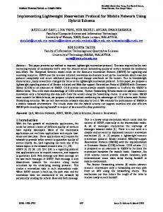
2.1 Network Architecture With DRRP, the network is partitioned into multiple domains, each consists of domain edge nodes (DE) and domain core nodes (DC) as shown in Fig. 1. DE deals with the control packets traversing through the domain. DC performs the data burst cut-through. As a burst is being launched, the source node simply selects a series of domains instead of individual nodes, while the path segment and wavelength through each domain are locally determined by the corresponding DE node.
Fig. 1. The Partitioning of the Network
Preliminarily, we first define group of adjacent switches as domains. For example, in Fig. 1, the network is divided into four domains, D1, D2, D3, and D4. Each domain consists of four DE switches. The ingress OBS node can select either D2-D4 or D3-D4 to deliver a data burst assuming the source node existed in D1 and destination node in D4. Each DE switch maintains full knowledge of the physical topology and dynamic link-state of its domain, including the detailed information about the channel availability of each link within the domain in the coming a few milliseconds. Thus, each DE can perform path selection for the arriving control packets in the domain with a much higher success probability than that by using FPR. This implies that it is not necessary for the source nodes to maintain full knowledge of the network topology. Thus, the proposed domain-based scheme is expected to result in dramatic reduction in signalling efforts due to the local routing update mechanism. As a control packet arrives at a DE, it first assigned labels which specify the arrival time of the corresponding data burst and the next domain, and then the control packet is forwarded to another DE access to the next domain. Once the DE receives the time and space labels, a local label assignment can be initiated by the DE to perform resource reservation along the path segment where the arrival time of the data burst is explicitly given. Note that the total nodal processing time and arrival time of the data burst for each intermediate nodes in the domain are determined at the DE. Here, the total nodal processing time is represented by the Domain Processing Time (DPT), which is specific to a DE-pair of a domain, and is updated when the path segment defined for the DEpair is changed. 2.2 DRRP Routing Assume the existence of a network topology similar to the one shown in Fig. 2. Every domain is treated as an autonomous system with its own intra-domain routing scheme. We define two types of routing paths, inter- and intra-domain paths. DE switches maintains an internal and external routing tables as well as a link reservation table (LRT). LRT is necessary to keep track of the link reservation status happening within in the domain. Since link channels are reserved based on computed domain offset time and burst cut-through time, the reservation time can be considered as a set of time slots δ reserved from time tx to ty. Table I illustrates the LRT at the switch. Upon allocating domains and their associated DE switches, every switch that corresponds to a domain is named based on the domain id Did and the switch id Sid. For example, DE and DC switches are named DE-Did-Sid, DC-Did-Sid respectively. Every DE switch exchanges the link state information with its associated DE nodes which belongs to the same domain. A Cost parameter is defined to reflect the path setup processing time and the link optical signal properties such as, maximum bandwidth, error rate, signal-to-noise ratio, and wavelength spacing. Every possible intra-domain path is examined to
determine its setup cost. The upper bound cost value is considered to be the DPT and stored in each DE switch. DC switches maintains their own routing information within their own domain by exchanging the routing information along its adjacent switches within the domain. DE switches maintains their routing information by exchanging link state information between both their domain switches and their adjacent domains DE switches. Ingress OBS routers maintain a full knowledge of the domains existed in the network by exchanging the routing information with DEs attached to the domains located in the network. Fig. 2 exemplifies the DRRP, where three domains are defined. The source node S maintains a routing table partially shown in Table II. To maintain the routing table at a source node, each domain disseminates information about the DE-pairs and the corresponding DPT of the domain as partially shown in Table III. DE maintains the shortest and possibly the second shortest paths existed in the domain Table IV illustrates the DE internal routing table. While a data burst is being assembled at source S, an inter-domain control packet is launched associated with the burst offset time and the burst length to DE-1-C. Recall, offset time is calculated based on the amount of time necessary to setup the domains along the path as illustrated in Section III. Once the control packet arrives to DE-1-C switch, the switch first examines the resource availability at the time when the data burst arrives. If the required resources are available, a special intra-domain control packet is created informing all the switches along the intra-domain path of the required reservation.
TABLE I Link Reservation Table for DE-1-C Reserve from Reserve to Number of slots
Link ID
δ DE-1-C to DC-1-G DC-1-G to DC-1-K
T0 T1 T3 …
T1 T2 T4 ….
13 6 9 …
TABLE II Routing Table for Node S Edge Pair Cost Processing Time 1C-1E C1 T1 1C-1H C2 T2 1C-1J C3 T3 3B-3E C4 T4 4F-4C C5 T5
Domain D1
D3 D4
TABLE III External Routing Table for DE-1-C Switch Domain Edge Pair Cost Processing Time D1 1C-1E C1 T1 1C-2H C7 T7 1C-2J C8 T8 D2 1C-2E C9 T9 D3 1C-3B C10 T10 D4 1C-4H C11 T11
Domai n D1
TABLE IV Internal Routing Table for DE-1-C Switch st nd Pair 1 Shortest 2 Shortest Path Path 1C-1E 1G,1F {1B,IF},{`B,1A} 1C-1H {1G} {1D},{1B,1F,1G},{1G,1K, 1L} 1C-1J {1G,1K} {1B,1F} ..... …. ….
Data burst cuts-through the arranged path by the domain. Because of the pre-defined data burst arrival time and the burst length, every switch LRT is automatically self update once the burst cut-through time is over. Table III and IV illustrates the external and internal routing tables for DE-1-C switch. Fig. 3 illustrates the time diagram for resource reservation along S-D specified in Fig. 2.
S
1C
1G 1K
1J
3B
Domain Processi ng
Fig. 2. The Routing Path from S to D
This intra-domain knowledge guarantees the resource availability for the incoming data burst. Upon the successful completion of this stage, the inter-domain control packet information is stored at the DE switch and then re-routed to the next DE, which is DE-2-B switch.
Time
Data Burst
Local Label Assignment in Domain 1
Local Label Assignment in Domain 3
Fig. 3. DRRP Time Diagram
3F 3G
3H
4E
4F
4G
4K
D
During the network operation, links are subject to congestion or operation failure. In such a situation, either an intra- or inter-domain path fails to operate. If an intradomain path fails, an alternative path e.g. second shortest path within the domain is selected. However, this operation results in high link-state signalling and LRT updates among all domain switches. Upon the link recovery, the path is back to normal routing and reservations. In case of inter-domain path failure, every OBS ingress router and adjacent DE switches updates their routing tables to avoid routing through the filed link. An alternative domains or DEs are considered for further routing. Maintaining updated LRT information at each switch is critical to the success of DRRP. Therefore, to quickly overcome any error in reservation updates and to increase the network adaptability, Fiber Optic Delay Lines (FDLs) can be deployed at the DE nodes. Proper engineering of FDL lengths and buffering time are critical to overall domain resource assignment and the LRT.
retransmission or loss of data integrity. However, having a too large offset time simply increases the end-to-end delay. How to compromise the two folds becomes a challenge, and will be left as our future study. 3.2 DRRP Domain Edge Node Admission Control DRRP aims to reduce the burst dropping probability by admitting incoming control packets if only a path can be setup within the domain. In case the domain internal paths and their channels are already occupied, the DE node reroutes the incoming control packets to other domain. This process increases the probability of the burst to be routed to the destination. Fig. 4 illustrates the flowchart of DE admission control procedure.
3. DRRP Analysis 3.1 DRRP Characteristics Emerging high processing and high bandwidth applications such as grid applications, which operate from hundreds to thousands of nodes, have emphasized the fact that current OBS network control and signalling cannot keep up with the requested demands. For example, grid applications can be functionally categorized as high bandwidth, multi-class, and multi-granularity traffic. Due to the mentioned application nature, more adaptable OBS routing and signalling schemes should emerge. DRRP has the ability to perform fast routing, early and accurately resource availability detection, decrease the overall network nodal processing time and increase the link utilization. The granted advantages enhance the overall network adaptability to such application demands. It is adaptable to large network sizes that include hundreds of nodes. DRRP can also serve as a basis of the effort in achieving inter-domain OBS network routing that supports multi-domain applications. Two types of nodal processing times are defined in DRRP, including domain edge node processing time tde and domain core node processing time tdc. To define the offset time for each data burst, we need to consider the both types of processing time. Assume the number of intermediate domains and number of core nodes of all the intermediate domains are d and c, respectively. An extra time delay tδ is added to ensure the completion of cutthrough routing within a domain. The total processing time tp for establishing a connection for an S-D pair is: tp = 2d tde + c tdc + tδ It is important to note that the offset time should not be smaller than tp such that early burst arrival can be avoided, which may lead to long delay due to
Fig. 4. Flowchart for DE Control
Upon the arrival of the control packet at the DE switch, the DE first checks its intra-domain routing table to see if there is any path able to be established within the domain. If yes, the DE selects the shortest one to forward the control packet which performs resource reservation along the path. If no path is available along the domain, a blocking is announced for the control packet.
4. Performance Evaluation Simulation was conducted to compare FPR, HHR, and DRRP on 8×6 mesh network as shown in Fig. 1, where Just-Enough-Time (JET) with delay reservation (DR) was implemented [2,8]. Network links were selected to be of the same length (100 KM) running at transmission rate of 2.488 Gb/s (OC-48) each with 1 fiber and 3 wavelength channels. The average burst length was of 100 MB. No wavelength converter and O/E/O conversion through a path are available. The packet arrival λ follows a Poisson distribution, while the burst size follows an exponential distribution. Since one link may service µ
DEs perform routing and are subject to extra nodal processing time, the nodal process time is much shorter. 7 JET-FPR
Packet Blocking
6
DRRP
4 3 2
0 0
0.2
0.4
0.6
0.8
1
1.2
1.4
Normalized Load
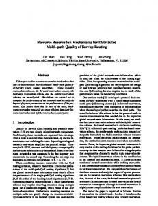
Fig. 6. JET-FPR, JET-HHR, DRRP Packet Blocking Rate
Fig. 6 shows the impact of using DRRP on the burst dropping rate. It clearly shows that the DRRP scheme yields a very low blocking rate compared with the other two schemes. FPR suffers from the highest blocking rate since it does not provide the flexibility of routing the control packets to avoid immediate blocking. HHR, on the other hand, can reduce the blocking rate at the expense of taking longer paths and higher nodal processing time. 0.8 0.7 0.6 0.5 0.4 0.3 0.2
JET-FPR
0.1
JET-HHR DRRP
0 0
0.2
0.4
0.6
0.8
1
1.2
1.4
1.2
1.4
Normalized Load
Fig. 7. JET-FPR, JET-HHR, DRRP Link Utilization 8.E-05 Retransmission Delay
0.2 Nodal Processing
JET-HHR
5
1
Link Utilization
more than one packet at the time, normalized load ρ was used. ⎛λ⎞ 1 ρ = ⎜⎜ ⎟⎟ ⎝ µ ⎠ Li where Li is the ratio between the number of connection requests to the average bandwidth requirement for each connection. To simplify the simulation, the domain partitioning and DEs assignment follows the arrangement shown in Fig. 1. In the simulation, HHR is implemented by selecting the shortest path between each S-D pair, which is defined in the routing table of each core node following the distance vector protocol. If the requested resource at the next hop is unavailable, the neighbor that follows any other shortest path is selected as the next hop (if there is any). If the second attempt failed to obtain a path, the control packet is simply dropped. On the other hand, FPR based on explicit routing where the source node determines the whole path before the connection request arrives. The unavailability of the requested resource at any intermediate node results in a burst dropping [7-9]. For DRRP, the routing within a domain is performed based on FPR with a pre-defined route connecting each DE-pair, while the domain selection is performed at the source node according to the disseminated link-state by each DE. The failure of finding any path within a domain results in blocking of the control packet. Figs. 5 to 8 demonstrate the performance in terms of nodal processing time, packet blocking, link utilization, and the delay caused by retransmission for FPR, HHR, and DRRP. The nodal processing time without and with a look-up-table process is set to be 3µs and 4µs, respectively. Burst dropping can occur at any node in the case of FPR or HHR, and it only occurs at DEs for DRRP since DEs knows if any wavelength channel during the specific time slot can be located for the coming data burst.
0.15 0.1 JET-FPR
0.05
JET-HHR DRRP
0 0
0.2
0.4
0.6
0.8
1
1.2
1.4
Normalized Load
JET-FPR
7.E-05
JET-HHR
6.E-05
DRRP
5.E-05 4.E-05 3.E-05 2.E-05 1.E-05 0.E+00 0
0.2
0.4
0.6
0.8
1
Normalized Load
Fig. 5. JET-FPR, JET-HHR, DRRP Nodal Processing Time
Once a burst is dropped, retransmission will be initiated immediately until the burst is successfully transmitted. Fig. 5 shows the average nodal processing time improvement due to the deployment of the DRRP scheme. The results indicate that HHR requires the most processing time since the routing decision is made at each node along the path. However, with DRRP, since only
Fig. 8. JET-FPR, JET-HHR, DRRP Average Retransmission Delay
Fig. 7 shows the link utilization for the three routing schemes. Compared with the other schemes, DRRP marginally increases the overall link utilization. Fig. 8 shows the resultant average delay if a burst is retransmitted whenever the burst is dropped. It is notable that the retransmission delay is proportionally related to the blocking rate, and FPR results in the highest blocking
rate. Therefore, it is under our expectation that FPR results in the highest retransmission delay. On the other hand, DRRP has the lowest dropping rate thus leading to the lowest retransmission delay. It is worth noting that the average delay is determined not only by the nodal processing time but also by the number of retransmissions due to burst dropping. The above simulation results have shown that DRRP OBS signalling achieves the lower packet dropping rate, average retransmission delay, and better processing overhead. It improves the routing fairness by combining the advantages of FPR and HHR.
5. Conclusion This paper has introduced a novel resource reservation and routing protocol for OBS networks, called DomainBased Resource Reservation Protocol (DRRP). The framework of DRRP is characterized by a graceful compromise between the FPR and HHR, in which the network is partitioned into multiple domains each with domain edges (DEs) handling resource reservation within a domain and inter-/intra-domain link-state exchanges for maintaining necessary routing tables. It is observed from extensive simulation results that the proposed scheme yields merits over conventional FPR OBS in terms of dynamicity, adaptability, efficiency, and traffic engineering capabilities under the given network environment and assumptions. Compared with HHR, DRRP provides better scalability and reduced control overhead in the network environment of distributed control.
6. Acknowledgements The authors would like to thank Majid Ghaderi for his discussions and illustration in various sections of conducting the simulation.
References: [1] Y Chen, C. Qiao, & X. Yu, Optical burst switching: a new area in optical networking research. IEEE Network, 18(3), 2004, 16-23. [2] C. Qiao, & M. Yoo, Optical burst switching (OBS), a new paradigm for an optical internet, Journal of High Speed Networks, 8(1), 1999, 69-84.. [3] Y. Xoing, M. Vandenhoute, & C. Cankaya, Control architecture in optical burst-switched WDM networks, IEEE Journal on Selected Areas in Communications, 18(10), 2000,1838-185. [4] M. Yoo, & C. Qiao, Just-Enough-Time (JET): A high speed protocol for bursty traffic in optical networks, Proc. IEEE/LEOS Technology for Global Information Infrastructure, Montreal, QC, 1997, 26-27. [5] C. Qiao, Labeled optical burst switching for IP-overWDM integration, IEEE Communication Magazine, 38(9), 2000, 104-14.
[6] Y. Lee, & B. Mukherjee, Traffic engineering in nextgeneration optical networks, IEEE Communications Surveys and Tutorials, 6(3), 2004, 16-33. [7] A. Kaheel, H. Alnuweiri, & F. Gebali, Analytical evaluation of blocking probability in optical burst switching networks, Proc. IEEE International Conference on Communication, France, 2004, 15481553. [8] K. Dolzer, C. Gauger, J. Spth, & S. Bodamer, Evaluation of reservation mechanisms for optical burst switching, International Journal of Electronics and Communications, 55(1), 2001, 18–25. [9] H. Vu, & M. Zukerman, Blocking probability for priority classes in optical burst switching networks, IEEE Communications Letters, 6(5), 2000, 214–216.