gantry-type machine with multiple assembly heads. ... most popular on the shop floor, but the complexity of ...... 2001 he was a Visiting Professor at Caltech.
192
International Journal of Control, Park Automation, and Systems, vol. 5, no. 2, pp. 192-199, April 2007 Tae-Hyoung and Nam Kim
A Dynamic Programming Approach to PCB Assembly Optimization for Surface Mounters Tae-Hyoung Park and Nam Kim Abstract: This paper proposes a new printed circuit board (PCB) assembly planning method for multi-head surface mounters. We present an integer programming formulation for the optimization problem, and propose a heuristic method to solve the large NP-complete problem within a reasonable time. A dynamic programming technique is then applied to the feeder arrangement optimization and placement sequence optimization to reduce the overall assembly time. Comparative simulation results are finally presented to verify the usefulness of the proposed method. Keywords: Dynamic programming, optimization, PCB assembly, surface mounters.
1. INTRODUCTION An important process in electronics manufacturing is the printed circuit board (PCB) assembly. The assembly of PCBs is a complex task involving the placement of hundreds of electronic components of different shapes and sizes at specific locations on the board. Efficient production of PCBs by automating and optimizing the planning process is essential in reducing product cost and thereby increasing competitiveness [1]. Surface mount technology (SMT) has replaced the older through-hole technology in many applications because it can dramatically increase component densities per board. Surface mounters are employed in the SMT process line to perform a sequence of component placements. Surface mounters can be divided into two types: turret type and gantry type. Turret-type machines have a moving feeder carrier, a moving X-Y table carrying the PCB, and a rotating turret with multiple assembly heads. Gantry-type machines have multiple stationary feeders, a stationary table, and a moving X-Y gantry with assembly head. A Multi-head surface mounter is a gantry-type machine with multiple assembly heads. Most surface mounters in industrial SMT lines belong to this category, such as the Yamaha YV-64/88/100, __________ Manuscript received January 6, 2006; revised October 22, 2006; accepted November 28, 2006. Recommended by Editorial Board member Young Il Lee under the direction of Editor Jae Weon Choi. This work was supported by the Regional Research Centers Program of the Ministry of Education & Hunan Resource Development in Korea. Tae-Hyoung Park and Nam Kim is with the School of Electrical and Computer Engineering, Chungbuk National University, Cheongju, Chungbuk 361-763, Korea (e-mails: {taehpark, namkim}@chungbuk.ac.kr).
Juki KE-750/760, Samsung CP-40/50 and Evest ECM-2000. This paper focuses on these multi-head surface mounters. The proper arrangement of component feeders in surface mounters and the placement sequence of components on the PCB are factors that can greatly effect the production cycle time of each machine and the overall system [2]. Many heuristics have been developed for improving productivity, but they are highly dependent upon the machine type applied. Crama et al. [2], Sohn et al. [3], and Ellis et al. [4] proposed heuristics based on a local search technique for a turret-type machine. Ball et al. [5], Kumar et al. [6], and Park et al. [7] developed PCB assembly planning algorithms applicable to gantry-type machines having a single head. Tirpak et al. [8] developed an optimization algorithm for gantry-type machines with resolver heads using a simulated annealing method. Leu et al. [9] proposed genetic algorithms for both turret-type and gantry-type machines. So far, quite a few studies have been conducted on multi-head surface mounters. These machines are most popular on the shop floor, but the complexity of multiple heads makes the optimization problem difficult to solve. Lee et al. [10] attempted to use a hierarchical optimization method for PCB assembly planning. Lee et al. [11] employed a genetic algorithm to obtain the feeder arrangement and placement sequence concurrently. This paper proposes new heuristics for the PCB assembly planning of multihead surface mounters. Section 2 defines the PCB assembly problem; section 3 formulates the problem mathematically; section 4 presents the developed optimization algorithm; and section 5 shows the simulation results.
A Dynamic Programming Approach to PCB Assembly Optimization for Surface Mounters
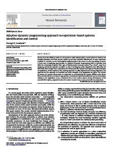
2. THE PCB ASSEMBLY PROBLEM A typical multi-head surface mounter is shown in Fig. 1. The gantry moves horizontally in the ydirection, and the heads move along the gantry in the x-direction. These x and y movements can occur concurrently. The nozzle on the head can move in the vertical z-direction to perform pickups and placements. It can also rotate around the vertical axis in order to properly align the components. Components to be assembled are supplied by feeders located at the pickup slots of stationary feeder lanes. Fig. 2 illustrates the assembly sequence of one cycle of a 3-head machine. The overall sequence consists of backward, pickup, forward, and place motions. The backward motion starts from the last placement location of the last cycle and ends at the first pickup location. In the pickup motion, each head picks up a component from its feeder in the sequence of the head number. The forward motion starts from the last pickup location and ends at the first placement location. Finally, in the place motion, each head places a component at the designated location of the PCB. We assume that the machine does not need additional nozzle changing time or vision inspection time, such as in the case of the YV-100 and the ECM-
193
2000. Also we assume that each head can pickup any component. The overall assembly time of a given PCB depends on two decision variables: (i) feeder arrangement - the assignment of the pickup slot locations, and (ii) placement sequence -the cycle and head in which the components are placed. The problem is to find the optimal feeder arrangement and placement sequence to minimize the overall assembly time.
3. PROBLEM FORMULATION To formulate the problem mathematically, we define the following sets:
C = {1," , nC }; set of components, E = {1," , nE }; set of component types, H = {1," , nH }; set of heads,
L = {1,", nL }; set of pickup slots, I = {1,", nI }; set of cycles, n where nI = C . Define τ : C → E as a type of nH function to identify components with component types, then Ce = {c τ (c) = e, ∀c ∈ C}
is the set of components that belong to the component type e ∈ E. Let zle ∈ {0,1} be the feeder arrangement variable
with the interpretation that zle = 1 if and only if pickup slot l contains the component type e. Also, let xihc ∈ {0,1} be the placement sequence variable
Fig. 1. A multi-head surface mounter (top view).
with the interpretation that xihc = 1 if and only if component c is placed by head h in cycle i. Then, the time elements required to perform a cycle i are represented as follows: Tibw =
Ti pu =
∑ ∑ ∑ t (nH , c1,1, l ) x(i −1)nH c1 xi1c2 zlτ (c2 ) , (1)
c1∈C c2∈C l∈L
nH −1
∑ ∑ ∑ ∑ ∑ t (h, l1, h + 1, l2 ),
h =1 c1∈C c2∈C l1∈L l2∈L
(2)
⋅ xihc1 zl1τ (c1 ) xi ( h +1)c2 zl2τ (c2 ) Ti fw = Ti pl = Fig. 2. Assembly sequence for one cycle of 3-heads surface mounter.
∑ ∑ ∑ t (nH , l ,1, c1 ) xilc1 xinH c2 zlτ (c2 ) ,
(3)
c1∈C c2∈C l∈L
nH −1
∑ ∑ ∑ t (h, c1 , h + 1, c2 ) xihc1 xi(h+1)c2 ,
(4)
h =1 c1∈C c2∈C
where Tibw , Ti pu , Ti fw , and Ti pl are the backward,
194
Tae-Hyoung Park and Nam Kim
pickup, forward and placement times of cycle i, respectively. t (h1 , loc1 , h2 , loc2 ) denotes the horizontal moving time from location loc1 of head h1 to location loc2 of head h2 . Actually, both the pickup time and the placement time should involve the vertical moving time and delay time of the z-axis. We assume; however, that all the time elements are not affected by changing feeder arrangement or placement sequence. The problem is to find the optimal values of
[ zle ] nL ×nE
where egh ∈ E is the component type that is picked up and placed by the head h ∈ H in a component group g. The same component group can appear in several cycles. Let ρ g be the number of cycles for a component group g, then
∑ ρ g = nI .
minimize∑ (Tibw + Ti pu + Ti fw + Ti pl )
(5)
∑ zle = 1, ∀e ∈ E ,
(6)
∑ zle ≤ 1, ∀l ∈ L,
(7)
i∈I
l∈L
e∈E
∑ ∑ xihc =1, ∀c ∈ C ,
(8)
∑ xihc ≤ 1, ∀(i, h) ∈ I × H .
(9)
i∈I h∈H
c∈C
Constraint (6) requires that each component type must be assigned to exactly one pickup slot, which implies that all components of the same type are picked from the same pickup locations. Constraint (7) requires that each pickup slot must contain at most one component type. Constraint (8) requires that each component must be mounted exactly once. Constraint (9) requires that each head can pickup and place at most one component in a cycle.
(10)
g∈G
n ×n ×n
and [ xihc ] I H C so that the overall cycle-time is minimized. Thus the optimization problem can be formulated as:
s.t.
e1g ," , egnH ,
The decision variables of the feeder arrangement problem are component group data egh and ρ g for all
g ∈G
and h ∈ H , and feeder arrangement
variables [ zle ] nL ×nE . These variables have a great effect on pickup, backward and forward time. For a component group g , we can represent the time elements as: Tˆgbw = ∑ t (nH , egnH ,1, l ) z Tˆgpu =
le1g
l∈L nH −1
,
(11)
∑ ∑ ∑ t (h, l1, h + 1, l2 ) zl1egh zl2egh+1 , (12)
h =1 l1∈L l2∈L
Tˆgfw = ∑ t (nH ,1, l , e1g ) z l∈L
legnH
(13)
.
Tˆgbw is the estimated backward time between the last
placement location and the first pickup location, where the last placement location is estimated by the center position of all components in C nH . Tˆgfw is eg
the estimated forward time between the last pickup location and the first placement location, where the
4. OPTIMIZATION ALGORITHM The problem formulated is a nonlinear integerprogramming problem with highly-coupled decision variables. To reduce its computational complexity, we decouple the variables and divide the problem into two sub-problems: feeder arrangement problem and placement sequence problem, which can yield a near optimal solution. 4.1. Feeder arrangement algorithm In a multi-head machine, the gantry transfers together several components from the feeder lane to the board. We define the component group as the set of component types transferred together along the gantry. Let G = {1," , nG } be the set of component groups, then the component group g ∈ G is defined as:
Fig. 3. Estimated time for feeder arrangement algorithm.
A Dynamic Programming Approach to PCB Assembly Optimization for Surface Mounters
first placement location is estimated by the center position of all components in C 1 . Tˆgpu is the actual eg
pickup time that is the same as (2). Fig. 3 illustrates definitions of (11)-(13). Now we have the criterion for the feeder arrangement problem as: minimize ∑ (Tˆgbw + Tˆgpu + Tˆgfw ) ρ g ,
(14)
g∈G
S4.2. Select two elements veh of the allocation matrix and toggle their values, then go to S1.2. As mentioned in S3.2, we use a DP search in order to get the feeder arrangement for a given component group. From (14), we obtain the following relation: min ∑ (Tˆgbw + Tˆgpu + Tˆgfw ) ρ g
(16)
g∈G
∑ ρ g ⋅ min(Tˆgbw + Tˆgpu + Tˆgfw ).
≤
(17)
g∈G
where the constraints in (6) and (7) should be satisfied. The feeder arrangement problem can be considered as an NP-complete problem. In NP-complete problems, it is often difficult to get the optimal solution within a reasonable time, thus a heuristic approach is developed in this research. The proposed feeder arrangement algorithm is as follows. Step 1: Component Allocation S1.1. Construct an allocation matrix [veh ] nE ×nH , where veh ∈ {0,1} is equal to 1 if and only if component type e is assigned to head h. S1.2. Construct an allocation-number matrix [ weh ] nE ×nH , where weh ∈ {0,1," ,| Ce |} is the number of component type e assigned to head h. So weh is greater than 0 if and only if veh = 1. The decision criterion is to equalize the total number of components for each head. Step 2: Component Grouping S2.1. Set the group index g = 1. S2.2. For each head h, select a component type e such that weh is maximized. We denote it as egh , and construct the component group < e1g ," , egnH
> . The ρ g is then obtained by
ρ g = min w h . h∈H
195
eg h
The component groups are pre-determined in S2.1S2.2. Hence the optimization problem of (17) is to arrange feeders for each component group. In order to reduce the difference between (16) and (17), we arrange feeders in the order of ρ g as S3.1. The object function in (17) can be rewritten as: Tˆgbw + Tˆgpu + Tˆgfw
= ∑ t (nH , egnH ,1, l ) z
le1g
l∈L
+"+
eg h
any non-zero weh is found, then increment g and go to S2.2. Step 3: Feeder Arrangement S3.1. Sort all component groups in descending order by ρ g . S3.2. For each component group, apply a dynamic programming (DP) search to find its feeder arrangement. Step 4: Improvement S4.1. Calculate the time in (14), if it is greater than the old time then stop and output the final results.
∑ t (1, l1 , 2, l2 ) zl1e1g zl2eg2
l1∈L l2∈L
∑ ∑ t (nH − 1, l1 , nH , l2 ) zl1egnH −1 zl2egnH
l1∈L l2∈L
+ ∑ t (nH , l ,1, e1g ) z l∈L
legnH
≡ J 0,1 + J1,2 + " + J nH −1,nH + J nH ,nH +1 ≡ J 0,nH +1 ,
where J i , j is the incremental cost between stages i and j. From the principle of optimality [12], the following recursive equations can generate the optimal solution: J n*H ,nH +1 = min J nH ,nH +1 ,
(18)
J n*H −1,nH = min{J nH −1,nH + J n*H ,nH +1 },
(19)
#
(15)
S2.3. For each head h, subtract ρ g from w h . If
+∑
* J 0, nH +1
= min{J 0,1 + J1,* nH +1 }.
(20)
DP is the enumerative search method to implement the above recursive relations. It guarantees a global optimal solution and can accommodate various constraints [12]. A search is done on the head-lane plane with nH + 2 columns and nL + 1 rows. Fig. 4 shows a head-lane plane for the 3-heads machine with 100 lanes. Each node in the plane denotes a specific position of the head. The node (0,0) denotes the starting position of backward motion. The node (h, l ) (h = 1," , nH , l = 1," , nL ) denotes a position where head h picks up a component from pickup slot l. Finally, the node (nH + 1, 0) denotes the end position of the forward motion.
196
Tae-Hyoung Park and Nam Kim
Fig. 4. Head-lane plane for DP search of feeder arrangement algorithm. nH = 3, nL = 100.
Now we can apply a typical DP algorithm to this search plane. The feeder arrangement variable z h = 1 if and only if the node (h, l ) is selected as leg
the optimal state. The computational complexity of DP is O(nH ⋅ nL 2 ). If we consider the component grouping, it becomes O(nG ⋅ nH ⋅ nL 2 ). Also,
nE nH C 2
iterations are required to toggle all pairs of the allocation matrix for improvement. Therefore, the feeder arrangement algorithm requires the complexity of O(nG ⋅ nH 3 ⋅ nL 2 ⋅ nE 2 ). Since the number of heads
Then improvement heuristics [13] such as two-opt and three-opt improves the tour by interchanging edges. Since this approach is a kind of local search, the overall performance depends highly on the performance of the initial tour. In this paper, we approach the placement sequence problem through the hybrid method. However, we also apply a DP search to the construction stage in order to generate a more efficient initial tour. Due to optimality property [12] of DP, our approach can reduce the overall moving time for placement. The placement sequence algorithm is given as follows. Step 5: Sequence Construction S5.1. Set cycle index i = 1. S5.2. Apply DP search to generate initial sequence of cycle i. S5.3. If i < nI , increment i and go to S5.2. Step 6: Sequence Improvement S6.1. Set component type e = 1. S6.2. Apply a two-opt algorithm to improve the sequence of component type e. Interchanging is done for all component pairs of Ce , and the performance is evaluated by (21) S6.3. If e < nE , increment e and go to S6.2. Similar to the case of the feeder arrangement problem, we can derive a DP formulation for the placement sequence problem. From (21), we have
4.2. Placement sequence algorithm The placement sequence problem is to determine the cycle and head number for each component to be placed. The results of the feeder arrangement algorithm should be considered in solving the problem. The decision variable is the placement sequence variable [ xihc ] nI ×nH ×nC , which has a great effect on backward time, forward time and placement time. The optimization criterion is as follows: minimize
∑ (Tibw + Ti pl + Ti fw ),
(21)
i∈I
where the constraints in (8) and (9) should be satisfied. All component locations on the board should be visited exactly once. The start and end location of the tour is a pre-determined waiting position of the head, so the problem can be regarded as a traveling salesman problem (TSP) involving multiple salesmen (heads) and via points (pickup locations). The most popular approach to TSP is using the hybrid method with construction heuristics and improvement heuristics. Construction heuristics [13] such as nearest neighbor and farthest insertion generates an initial tour.
∑ (Tibw + Ti pl + Ti fw )
(22)
∑ min ( Tibw + Ti pl + Ti fw ).
(23)
min
nH is usually less than 10, it is computationally tractable.
i∈I
≤
i∈I
Using (1), (3), and (4), the evaluation function in (23) can be rewritten as: Ti fw + Ti pl + Tibw
∑
=
c∈Cτ ( c )
+
t (nH , lτ (c ) ,1, c) xi1c
∑
∑
t (1, c1 , 2, c2 ) xi1c1 xi 2c2 + "
∑
∑
t (nH − 1, c1 , nH , c2 ) xi1c1 xi 2c2
c1∈Cτ ( c1 ) c2∈Cτ ( c2 )
+
c1∈Cτ ( c1 ) c2∈Cτ ( c2 )
+
∑
c∈Cτ ( c )
t (nH , c,1, lτ (c ) ) xinH c
≡ J 0,1 + J1,2 + " + J nH −1,nH + J nH ,nH +1 ≡ J 0,nH +1. lτ (c ) ∈ L is the pickup slot location for the component type c ∈ C , which is the output value of the feeder arrangement algorithm. The recursive relations in (18)-(20) are also valid
A Dynamic Programming Approach to PCB Assembly Optimization for Surface Mounters
197
5. SIMULATION RESULTS
Fig. 5. Head-component plane for DP search of placement sequence algorithm: nH = 3, nC = 200. for this problem. The search plane consists of the head axis and the component axis. The head axis has nH + 2 columns, and the component axis has nC + 1 rows. Fig. 5 shows a search plane with 3 heads and 200 components. The node (0,0) denotes the start location of forward motion. The node (h, c) (h = 1," , nH , c = 1," , nc ) denotes the location on which head h places component c. The type of component c should be matched with that of the component picked up by h. So the node (h, c) is valid if the condition τ (c) = eih is satisfied. Finally, the node (nH + 1,0) denotes the end location of the backward motion. A typical DP algorithm is directly applied to this search plane. The placement sequence variable xihc = 1 if and only if the node (h, c) is selected as the optimal state. The computational complexity of the construction stage is O(nH ⋅ nC 2 ), and that of the improvement stage is O(nC 2 ). Hence, the placement sequence algorithm requires the complexity of O(nH ⋅ nC 2 ), which is less than that of the feeder arrangement algorithm. Both of sub-problems in (14) and (21) are still nonlinear problems but they are decoupled to get a practical solution. It is very hard to identify the difference between solutions of the sub-problems and original problem. In (14), we assume that the placement time Ti pl
is not effected by feeder
arrangement variables, so the feeder arrangement stage generates a solution without considering placement time. But the placement time is considered at the stage of placement sequence to close the solution to the global one.
A simulation was performed for an ECM-2000 machine using commercial PCBs in order to evaluate the proposed approach. The algorithm was implemented using Microsoft Visual C++ under Microsoft Windows XP on a Pentium IV 3.0GHz/ 512MB computer. The feeder arrangement and placement sequence were generated as text files for the set of 10 PCBs in Table 1. These files were exported to the vendor-made graphic simulator ECM2000, which displays the assembly procedure and estimated assembly time. ECM-2000 is a multi-head surface mounter with 4 heads or 6 heads (optional). A total of 84 slots are available in the front and rear feeder lane. The distance between heads is 20 mm, and the distance between slots is 10 mm. Each axis is actuated by its AC servo motor and driven by an S-curve profile. The results were compared to the solutions obtained using the commercial vendor-made software ECOPTIMIZER V1.0. Also we made greedy algorithms to show the contribution of the DP method more definitely. At the feeder arrangement stage, the greedy method arranges the feeder component type with the maximum components to the nearest lane from the center of the PCB. At the placement sequence stage, the greedy method uses the nearest-neighbor search to construct the initial tour. In this simulation, we compared the results for 4 cases: 1) vendor-made 2) greedy + greedy 3) greedy + DP 4) DP + DP. The second case means that the greedy method replaces the DP method at both feeder arrangement stages and placement sequence. The third case means that the greedy method replaces the DP method at the placement sequence stage only. Table 2 compares the assembly times from the Table 1. Sample PCBs. PCB No. of Id component types 1 7 2 10 3 21 4 31 5 43 6 53 7 58 8 61 9 79 10 83
No. of Components 48 55 310 155 111 396 107 464 267 723
198
Tae-Hyoung Park and Nam Kim
Table 2. Assembly time of 4-heads machine (sec). PCB Id 1 2 3 4 5 6 7 8 9 10
Vendormade 29.9 29.6 237.5 87.3 77.3 267.6 70.4 326.1 169.3 529.8
Greedy + Greedy + Greedy DP 30.3 29.2 30.1 29.2 240.0 230.6 90.1 88.1 78.1 75.5 267.8 257.1 71.1 67.1 330.1 315.2 168.1 157.8 519.9 484.8
DP + DP 27.5 27.0 208.5 79.0 69.6 232.3 60.5 285.7 143.9 430.2
Table 3. Assembly time of 6-heads machine (sec). PCB Vendor- Greedy + Greedy + DP + Id made Greedy DP DP 1 28.5 29.1 28.8 26.0 2 28.0 28.9 27.1 25.8 3 223.5 227.0 218.0 195.6 4 84.0 87.0 82.1 73.8 5 75.3 76.7 72.9 65.4 6 246.0 253.7 240.8 214.0 7 65.5 66.0 63.8 56.0 8 298.8 305.9 293.0 257.0 9 159.0 165.1 159.3 133.9 10 501.0 510.1 489.2 400.3 proposed method with those from the other methods, where all of them were applied to a 4-head machine. The proposed method (method 4) reduced assembly time by about 12.2 %, 12.9 % and 9.0 % compared to method 1, method 2, and method 3, respectively. The improvement ratio tended to increase as the component-type size increased. The table shows that the introduction of the DP method in both stages reduces the assembly time for all cases. Also, the DP method in the feeder arrangement stage has a greater effect on performance improvement. Table 3 compares the same items as Table 2, where they were applied to a 6-head machine. For all PCBs, a 6-head machine required lower assembly time than a 4-head machine. The proposed method (method 4) reduced assembly time by about 13.2 %, 15.2 % and 11.5 % compared to method 1, method 2, and method 3, respectively. The improvement ratios for a 6-head machine were better than those for a 4-head machine. The simple heuristics usually generates worse results as the problem becomes more complex. Since the other methods use simpler heuristics than the proposed method, those results become worse as the number of heads increase. Finally, Table 4 shows the computation time of the
Table 4. Computation time for 4-heads machine (sec). PCB Vendor- Greedy + Greedy + DP + Id made Greedy DP DP 1 1 1 1 2 2 2 1 2 2 3 36 35 36 45 4 30 19 20 23 5 54 51 58 67 6 102 97 112 160 7 115 112 117 135 8 121 185 201 400 9 242 250 381 878 10 412 452 752 806 applied methods. The proposed method took relatively longer to get better solutions. The computation time depends on the complexity of component distribution as well as the number of components and component types in the PCB. Since the algorithm is utilized as an offline solution, the larger calculation time can be allowed if it reduces the overall assembly time of the PCB assembly system.
6. CONCLUSIONS A PCB assembly planning method was presented to improve the productivity of a surface mounter. Most research has focused on turret machines or singlehead gantry machines. This research attempted to create an effective heuristics for multi-head gantry machines, which are the most popular types in the current SMT line. The feeder arrangement and placement sequence were determined hierarchically, and each algorithm used a hybrid scheme with construction and improvement. To increase the performance considering the multiple heads, a dynamic programming search was applied to each algorithm. An integer-programming formulation was also presented to identify the problem mathematically. The computer simulation was done for a commercial machine using actual board data, and the results showed the usefulness of the proposed method. [1] [2]
[3]
REFERENCES T. L. Landers, W. D. Brown, E. W. Fant, E. M. Malstrom, and N. M. Schmitt, Electronic Manufacturing Processing, Prentice-Hall, 1994. Y. Crama, J. Klundert, and F. C. R. Spieksma, “Production planning problems in printed circuit board assembly,” Discrete Applied Mathematics, vol. 123, no. 1, pp. 339-361, 2002. J. Sohn and S. Park, “Efficient operation of a surface mounting machine with a multihead turret,” Int. J. of Production Research, vol. 34, no. 4, pp. 1131-1143, 1996.
A Dynamic Programming Approach to PCB Assembly Optimization for Surface Mounters
[4]
[5]
[6]
[7]
[8]
[9]
[10]
[11]
K. P. Ellis, F. J. Vittes, and J. E. Kobza, “Optimizing the performance of a surface mount placement machine,” IEEE Trans. on Electronics Packaging Manufacturing, vol. 24, no. 3, pp. 160-170, 2001. M. O. Ball and M. J. Magazine, “Sequence of insertions in printed circuit board assembly,” Operations Research, vol. 36, no. 2, pp. 192-201, 1988. R. Kumar and H. Li, “Integer programming approach to printed circuit board assembly time optimization,” IEEE Trans. on Components, Packaging, and Manufacturing-Part B, vol. 18, no. 4, pp. 720-727, 1995. T. H. Park and C. H. Kim, “Assembly sequence planning for a chip mounter using transportation algorithm,” Proc. of the SICE Annual Conference, vol. 1, 2000. T. M. Tirpak, P. C. Nelson, and A. J. Aswani, “Optimization of resolver head machine using adaptive simulated annealing (ASA),” Proc. of IEEE/CPMT Int’l Electronics Manufacturing Technology Symposium, pp. 214-220, 2000. M. C. Leu, H. Wong, and Z. Li, “Planning of component placement/insertion sequence and feeder setup in PCB assembly using genetic algorithm,” J. of Electronic Packaging in Trans. of the ASME, vol. 115, no. 12, pp. 424-432, 1993. S. H. Lee, J. M. Hong, D. W. Kim, and B. H. Lee, ”An effective algorithm for a surface mounting machines in printed circuit board assembly,” Proc. of IEEE/RSJ Int. Conf. on Intelligent Robots and Systems, vol. 1, pp. 932937, 1997. W. S. Lee, S. H. Lee, Y. D. Lee, and B. H. Lee, “Improving the productivity of a multi-head surface mounting machines with genetic algorithms,” Proc. of IEEE/RSJ Int. Conf. on Intelligent Robots and Systems, vol. 1, pp. 17801785, 1999.
199
[12] Z. Michalewicz and D. B. Fogel, How to Solve It: Modern Heuristics, Springer-Verlag, 2000. [13] G. Reinelt, The Traveling Salesman Problem: Computational Solutions for TSP Applications, Springer-Verlag, 1994. Tae-Hyoung Park received the Ph.D. degree in Control and Instrumentation Engineering from Seoul National University, Korea in 1994. From 1994 to 1997, he was a Senior Research Engineer of Samsung Techwin Co., where he developed the optimization software for PCB assembly systems. Since 1997 he has been a Professor in the Dept. of Control and Instrumentation Eng. at the Chungbuk National University. From 2000 to 2001, he was a Visiting Professor at the University of Toronto. His research interests include robotics, optimization algorithms, machine vision, and electronic manufacturing systems. Nam Kim received the Ph.D. degree in Electronics Engineering from Yonsei University, Korea in 1988. Since 1989, he has been a Professor in the Dept. of Computer and Communication Eng. at the Chungbuk National University. From 1992 to 1993, he was a Visiting Professor at Stanford University. From 2000 to 2001 he was a Visiting Professor at Caltech. His research interests include optimization theory and control applications of optical measurement system.