A Fast B1 Mapping Method for Transmit/Receive Coils for Parallel Transmit (pTx) Applications. T. Zhao1, H. Zheng2, A. DeFranco3, T. Ibrahim2,3, Y. Qian3, and ...
A Fast B1 Mapping Method for Transmit/Receive Coils for Parallel Transmit (pTx) Applications 1
T. Zhao1, H. Zheng2, A. DeFranco3, T. Ibrahim2,3, Y. Qian3, and F. Boada2,3 Siemens Healthcare, Siemens Medical Solutions, Pittsburgh, Pennsylvania, United States, 2Bioengineering, University of Pittsburgh, Pittsburgh, Pennsylvania, United States, 3Radiology, University of Pittsburgh, Pittsburgh, Pennsylvania, United States
Introduction: For a successful parallel transmit experiment, the B1 map must be known for each Tx channel. As the number of the transmit channel increases, the total scan time of B1 mapping could increase significantly. Because of this, there is a tremendous motivation to find a fast B1 mapping method for pTx application in the recent years. Many methods have been proposed to measure B1+ map, such as Bloch-Siegert [1], SDAM [2] and AFI [3]. However, there are various advantages and disadvantage with these B1 mapping methods for parallel transmit (pTx) applications at ultra high field (i.e., 7T). Due to fast T2* decay at ultra high field as an example, Bloch-Siegert could not be used for orbital-frontal lobe region due to its long RF pulse and thus long needed TE, which showed a significant signal dropout in this region. On the other hand, large tip angle pulses could run into SAR limitation, which leads to prolonged scan time for B1 mapping. Further, without rough idea of B1 distributions, the large tip angle pulses, such as 180-refocus pulses and saturation pulses used in these methods will not perform well. In the abstract, we propose a fast technique to estimate B1+ map for pTx using only the small tip angle data. Methods: In past years, we have consistently observed that the square sum of B1+ and B1- maps are all very similar for all our multi-channel Tx/Rx coils (>6 coils, TEM/Surface Loops). With this observation, we proposed the following procedures to quickly estimate the B1+ map for pTx applications using only data from small tip angle scans. The following assumptions are proposed based on our observations, (1) The square sum of B1+ and B1- maps, Isq, are equal or very close as shown in the Eq.1. (2) The map of square sum of (B1+B1-) is relatively smooth, that is a low pass filter can be used to extract this map for in vivo data. Define N as the total number of Tx (or Rx) channels for a given Tx/Rx coil. A low tip angle image can be obtained quickly by transmitting each Tx channel sequentially and always receiving with all available receiving channels. The image intensity for a given pixel, Ii, from such a image is directly proportional to the B1+ map of that channel, i, the receiving B- profiles and the proton density of that pixel, ρ, as given in Eq.2. By a simply summation all the images that obtained via sequentially exciting with each Tx channel, a total image sum image, Itot, can be obtained as in Eq.3., which is function of Isq and ρ. Since Isq is smooth (see Fig.1), a low pass filter can then be applied to filter out the proton density information, which gives a quick estimate of the Isq map from the measured Itot map. Defining a ratio map, R, as the ratio between the i-th Tx channel image and the total sum image, Itot. The B1+ map can thus be shown to be only related with maps of R and Itot. Rearrange Eq.4, the B1+ map for the i-th channel is indeed directly proportional to the measured Ri and estimated Isq maps.
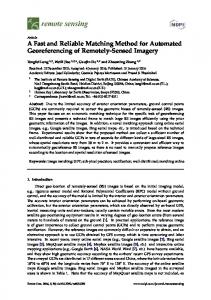
Fig. 1 (a) the sum of (B1+)2 map and (b) the sum of (B1-)2 map for the three plane view from simulation.
Results and Discussion: The simulation method used in this study was identical to those presented in the previous publications[5, 6]. A human model was used for simulating B1 maps for a four channel Tx/Rx TEM coil and was used to verify the proposed B1 estimation algorithm. All in vivo experiments were carried out on the 7T Siemens scanner with the pTx capabilities and an 8-channel Tx/Rx coil was used. The B1 maps were obtained by sequentially exciting each Tx channel using the 2D GRE sequence with the following parameters, TR/TE = 200ms/2.51ms, flip angle = 8°, bandwidth per pixel = 1500 Hz/pixel, FOV = 220mm and matrix size = 64×64. The total scan time is only 1min42s for all 8-channels. The B1 maps for each channel was then calculated using those low flip angle data as outlined above. The interleaved spiral/EPI trajectories were numerically designed with a maximal gradient amplitude, 24mT/m, slew rate of 80mT/m/ms, FOV = 200mm, and matrix size = 32. The acceleration factor for localized excitation was two with spiral trajectory. A 3spoke trajectory was used to design pTx RF pulses that excited a 2D slice with uniform excitations. Fig.1 shows maps of the sum of (B1+)2 and (B1-)2 from all four channels from the simulation. It is evident that these two maps with three plane views all demonstrated clear similarities. This justified our assumption as shown Eq.1. The behavior was observed with all our Tx/Rx coils (>6 different coils). With home written simulation program, we can also simulate directly the images of the low flip angle GRE experiments. The simulation data was then fed to the proposed B1 mapping Fig. 2 (a) real B1+ maps and (b) the routine to produce a estimated B1 map. Fig.2 showed the simulated B1+ map (top row), estimated B1 map using proposed estimated B1+ maps from the new method from the simulated small tip angle data (middle row) and the difference between the two maps (bottom row). These method, and (c) the difference data confirmed that the proposed B1 mapping method produced a reasonable accurate B1 maps with only some minor between real and estimated B1 maps. discrepancies. Interestingly, the error distributions of estimated B1 map seems to be similar for all four Tx channels, which partially indicated that there were some discrepancies between sum of (B1+)2 and (B1-)2 maps. However, we noticed (data not shown) that the discrepancies between sum of (B1+)2 and (B1-)2 maps become smaller with increased Tx channels. Thus, the estimated B1 maps from the proposed method are expected to more accurate with more Tx channels. To demonstrate the application of the proposed B1 mapping method, two healthy subjects was recruited and the B1 maps was estimated using the proposed method for the 8-channel Tx/Rx coil with 8 loops evenly distributed on the surface of a cylinder. The localized excitations with the desired rectangle pattern were shown in Fig.3 (left, middle) for the two subjects. The pulse was designed using the small-tip angle approximation as proposed by Grissom and et al.[4]. Also a 3-spoke RF was Fig. 3 In vivo pTx results using the B1 maps estimated using the low flip designed to produce a uniform excitation was shown in Fig3 (right). The intensity angle images. (a) Localized excitation for subject 1, (b) localized excitation variation was confirmed to be from the receiving side (data not shown). A flat for subject 2, and (3) uniform excitation with 3-spoke RF design. image, thus uniform excitation, was obtained by removing this receiving profile. The presented pTx results showed similar quality to those with other B1 mapping methods, which also confirmed the accuracy of the proposed method. It is worth to notice that the total scan time for obtaining the B1 maps of the whole brain for a 8-channel Tx/Rx coil is only 1min42s with very low SAR. Conclusion The proposed methods can be used for quick estimating the B1 maps for pTx application using only the small tip angle data. References: [1] Sacolick, L., et al., MRM 2010; 63:1315. [2]Cunningham, C., et al., MRM 2006; 55:13. [3] Yarnykh, V., Magn Reson Med 2007; 57:192. [4] Grissom, W., et al., MRM 2006; 56:620. [5] Ibrahim, T., et al, ISMRM 2008, p438. [6] Ibrahim, T., et al., ISMRM 2010, p392.
Proc. Intl. Soc. Mag. Reson. Med. 19 (2011)
2925