A Fast, Reliable and Lightweight Distributed Dissemination Protocol for Safety Messages in Urban Vehicular Networks Sofiane Zemouria,∗, Soufiene Djahela , John Murphya a UCD
School of Computer Science and Informatics, Ireland
Abstract It is foreseeable that in the few upcoming years, real time traffic information, including road incidents notifications, will be collected and disseminated by mobile vehicles, thanks to their plethora of embedded sensors. Each vehicle can thus actively participate in sharing the collected information with the other peers forming an infrastructure-less self-organizing network of vehicles. However, the fast development of applications in ITS field may result in an excessive load on such a network; therefore an efficient use of the available bandwidth is highly required. Not only should the size of the data inserted in the network be properly controlled, but also the extent of each message should be accurately defined. In this paper, we propose a distributed dissemination protocol for safety messages in urban areas, dubbed ”Road-Casting Protocol (RCP)”, which is based on a novel cooperative forwarding mechanism. Moreover, an accurate definition of the Region of Interest (RoI) (i.e. the geographical scope) of each broadcasted safety message is also devised to ensure better control of the network load. We have evaluated the efficiency of the RCP along with the proposed RoI definition using realistic simulations, based on an accurate propagation loss model for urban vehicular ad hoc network communications, and the obtained results show a substantial improvement, compared to state of the art schemes, in terms of enhanced packet delivery ratio up to higher than 95%, lower end-to-end delay and reduced network load. Keywords: VANETs, Data Dissemination, Broadcasting, Safety Messages, Region of Interest, Urban Areas, Non-Line-of-Sight, ITS. 1. Introduction Cities generate an enormous amount of data everyday. The efficient use of this information promises to revolutionize our daily lives, thanks to the “Ubiquitous Intelligence”. In fact, computers, sensors, microchips, digital networks and other electronic systems will participate in the near future in the democratization of the ubiquitous computing, that is to say, the fusion of the virtual and the real worlds to create environments called “Intelligent” which can offer a multitude of highly available services to their end users. One typical example of these applications is the Intelligent Transportation Systems (ITS) which main aims are (i) improving safety in transportation (ii) increasing the efficiency of transportation systems with a more efficient management of the road infrastructure, and (iii) improving user comfort by providing a multitude of information services, decision support, guidance, and Internet access. All this with the objective of integrating the transportation in a sustainable development policy: ranging from reducing greenhouse gas emissions, to optimizing the maintenance of the road infrastructure. Such applications are made possible with the emergence of a new type of wireless networks: The Vehicular Ad Hoc Networks (VANETs).
∗ Corresponding
author Email addresses:
[email protected] (Sofiane Zemouri),
[email protected] (Soufiene Djahel),
[email protected] (John Murphy) Preprint submitted to Elsevier
The most promising among these applications is safety in transportation, in which the drivers should be notified early in advance about potential hazards on the road to ensure faster reaction to avoid them, leading to time saving with reduced money and lives losses. According to some studies published in [1], 60 % of accidents could be avoided if drivers were provided with a warning half a second before the moment of collision. However, reaching this objective might not be an easy task to accomplish. In fact, the critical nature of safety applications requires that all emergency messages reach their destinations within a short delay (i.e. short latency), and under high communication reliability conditions compared to other application classes. Spreading an emergency message in VANETs is a cooperative process between vehicles. If not well designed, this process also called broadcasting, usually leads to an excessive load on the shared radio channel, especially in highly dense scenarios where high packets collision and lower reception rates are most likely to be observed. One additional issue where broadcasting an emergency message is the narrow communication medium. This latter, located around the frequency band of 5.9GHz, is expected to carry a large spectrum of growing mobile distributed applications in the near future. This might weigh heavily on the limited resource reserved to this end as more than one vehicle can attempt to access it simultaneously. The ETSI standard defines five radio channels in Europe [2] for inter-vehicular communications, and seven channels in USA [3]; including one control channel (CCH) for both standards, which is reserved for both periodic beacons and the exchange September 21, 2014
of emergency information. Each radio channel is 10 MHz wide. In order to allocate more bandwidth for emergency messages transmissions, a multitude of solutions have been proposed to control the load of beacons on the shared CCH, which can mainly fall under one of the two categories: the first one focuses on reducing their transmission rates in highly congested scenarios while the second category proposes to adapt the transmission power of the beacons’ senders. In 2011, ETSI TS released a Technical Specification namely DCC [4] (the Decentralised Congestion Control), which combines different techniques to control the load generated by beacons on the radio channel. We refer the reader to [5] for further information about DCC. As opposed to these approaches, we focus in this work on designing a novel technique that fulfils the requirements of safety messages dissemination regardless of the employed beacon transmission rate and power. Note that beacons transmission rate and power control is out of the scope of this work. The impact of beacons frequency generation and their transmission range on the performance of our dissemination protocol is also not considered in this work. One of the main criteria that determine the efficiency of dissemination protocols in VANETs is the appropriate selection of the next forwarder of an emergency message [6]. If not carefully selected, the next forwarder could have received corrupted information and might introduce further errors in the broadcast message [7], could be in a high density area raising the probability of collisions in case it further forwards the emergency message, and thus the loss probability of the disseminated packet [8]], or might have a restricted number of reachable neighbour vehicles and therefore limiting the message reachability and minimizing its benefits [9]. In several existing protocols, the decisive element for the next forwarder vehicle selection is the distance: the furthest the receiver is from the sender, the more chances it gets to be selected as the next forwarder. This approach reduces the number of intermediate hops, which consequently lower the end-to-end delay. However, it is well known that the quality of the communication link drops with longer transmissions, therefore more attention should be paid to this key parameter in order to reduce the risk of safety messages corruption. An alternative solution would be to choose a closer receiver as a next forwarder instead of the furthest one. In this case, the sender-receiver distance becomes shorter, requiring the safety message to hop in more intermediate transmitters and resulting in a higher end-to-end delay. In addition, a single vehicle is usually selected to rebroadcast the safety message in most of the existing solutions. In the absence of a proper packet loss recovery mechanism especially in standards like DSRC WAVE [3] and ETSI TS G5 [2], a simple packet collision could lead to the permanent loss of the information contained in it before it reaches its destination. This effect can be amplified in urban areas where the roads are surrounded by buildings shadowing the signals [10], and therefore considerably limiting the transmissions behind the buildings and around the corners [11] In this paper, we tackle the problem of safety messages dissemination in Urban Vehicular Networks. In our previous work [12] we proposed a protocol that operates in the Medium Ac-
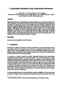
Figure 1: A precise Region of Interest (RoI) of a safety message (in yellow), destined to all vehicles driving towards the accident location, vs. a circular RoI
cess Control layer, which deals with the network overload by controlling the number of retransmissions of each emergency message. In this work, we extend the protocol to a cross-layer solution that also controls the size of emergency messages as well as their extent, in addition to their number of retransmissions. Our new solution addresses the problem of the network overload by considering two main aspects: the first one, which is an enhancement of our previous work [12] consists of (i) selecting a set of forwarders with regard to two parameters: the distance between the sender and the forwarder taking into account the relative position of the receiver from the junction and the estimated transmission range; and the link quality including the channel quality, the vehicle mobility and the non-line of sight conditions; and the second aspect, which represent the novelty of this work, focuses on (ii) introducing a novel distributed way to accurately define the effective Region of Interest (RoI) of an emergency message based on the connectivity of the road map graph. The enhancements in the first aspect (forwarding mechanism) consist of a new probability assignment function that takes into account new parameters like the distribution of vehicles with regard to their locations. For example, it is expected that a higher density will be observed in intersections. We argue that a precise definition of the RoI for a safety message is very important to limit the unnecessary load on the communication network, as this will only spread the information in the area where vehicles need it, freeing the channel in the rest of the areas for other uses. Figure 1 gives a visual representation of the potential gain that can be made when using this method. J¨ochle and al. [13] showed that an effective definition of the RoI is a tradeoff between the preciseness of the latter and the size of the emergency message. The proposed Road-Casting Protocol (RCP) enables a more accurate definition of the RoI, compared to the existing schemes (e.g. the circular RoI), without increasing the size of the safety message. To the best of our knowledge, we are the first to propose a solution that deals with the RoI definition issue for safety information in VANETs. The remainder of this paper is organized as follows. In section 2 we give an overview of the most significant related works 2
and highlight their limitations. Afterwards, we present our solution in details in sections 3 and 4. In section 5, we present and analyse the obtained simulation results. Finally, the conclusion and future work are outlined in section 6.
without compromising the end-to-end delay. In addition, this protocol makes use of two types of directional antennas for a road segment transmission and an intersection transmission respectively. Multi-hop Vehicular Broadcast (MHVB) [16] is a protocol that deals with the network overload by regulating the transmission rate based on the traffic congestion level. This protocol also uses the delay to differentiate the next forwarders, similarly to EDB, as it assigns the shortest waiting time to the furthest vehicle from the sender. After the waiting time expiration, the next forwarder vehicle rebroadcasts the safety packet, and any of its neighbors that hears this duplicate rebroadcast, with regard to the recently received safety packet, will cancel its packet-rebroadcast process. Reliable Method for Disseminating Safety Information (RMDSI) [17], another delay-based broadcast protocol, deals with the network fragmentation problem by using the store, carry and forward feature. The main shortcoming for these solutions is the lack of consideration for the quality of the channel. In fact, receiver vehicles at a long distance from the source might receive a signal, but no guaranty on the integrity of the received information exists (gray zone problem [18]), as no error detection or correction mechanism is included in these protocols. The probabilistic multi hop broadcast approach relies on a distance proportional probability function that is calculated on each receiving vehicle. As an example for this category, the Weighted p-Persistence Protocol [19]. The vehicle receiving a packet the first time will calculate a probability based on the distance separating it from the sender, and the vehicle with the highest probability will be selected as the next forwarder. The Irresponsible Forwarding (IF) [20] also falls into this category, as it sets the receiver vehicle to compute a probability based on the distance between itself and the sender vehicle, but also based on the density of vehicles in its surroundings. The main issue about this class of protocols is the partiality of the probability assignment function as it considers the distance factor only, for the majority of solutions, and the density of the vehicles in some specific cases, without taking into account the quality of the received signal. The third category, which is the network coding based multi hop broadcast is the newest amongst all three classes. A good overview of the network coding approach can be found in [21]. The basic concept around this approach is to reduce the number of packet transmissions by encoding multiple packets into one preforming a XOR. The receivers will be able to retrieve the packet intended to them, providing that they previously received all the enclosed messages except the new one. CODEB (Coding based Broadcast Protocol) [22] is a good example in this category. This protocol relies on opportunistic coding and listening approaches where each vehicle is set on a promiscuous mode and stores as many packets to use them for decoding the received message. Although, this class promises to reduce considerably the load on the radio channel, it is not very clear yet how it can be applied to VANETs, since more complexity is added when the vehicles do not know explicitly their neighbours or the exact recipients of their messages. Besides, a sender of a message should select explicitly the next
2. Related Work As pointed out in the previous section, various solutions and protocols were proposed to reduce the overhead on the communication channel. This is a common problem for all application classes in VANETs, but we will focus in this work on the safety applications’ requirements for the shared radio medium. Most of the literature solutions mainly focus on (i) maximizing the reception rates and (ii) minimizing the end-to-end delay while (iii) keeping the channel at an acceptable level of congestion. In this section, we will explore some of the most important works that have been proposed to improve the above-cited three elements, and evaluate their feasibility in road safety scenarios. The most common classification for broadcast protocols [6] divides the literature solutions into: • Delay based multi hop broadcast • Probabilistic based multi hop broadcast • Network coding based multi hop broadcast In the first category, different waiting delays are assigned to the receivers before granting them the access to the channel to rebroadcast their packets. Generally, the furthest vehicle from the sender is explicitly selected as the next forwarder to maximize the progress of the packet. Urban Multi-hop Broadcast (UMB) [14] relies on the RTB (Request To Broadcast) and the CTB (Clear To Broadcast) control messages to address the black storm and the hidden node problems as the transmitter of a packet will not start its transmission unless a CTB is received. First, the sender will broadcast a RTB and the receiving vehicles in its transmission range will start transmitting a jamming signal called black-burst for a specified period of time. Each vehicle will calculate this time based on the distance separating it from the sender. The furthest the node is from the source, the higher the black-burst period will be. By the end of this period, a potential forwarder vehicle will listen to the channel again and will only reply by a CTB if the medium is free. Using this technique, the furthest receiver vehicle, will be explicitly picked by the sender as the next forwarder. However, assigning the longest waiting period (black-burst) to the forwarder vehicle will increase the end-to-end delay, which does not comply with the safety class of applications’ requirements. To overcome the limitations of UMB, the Efficient Directional Broadcast (EDB) [15] was proposed. Using this protocol, the furthest node from the source will be assigned the shortest waiting period before retransmitting the packet. Furthermore, the RTB and CTB control packets are removed. When a sender vehicle broadcasts a packet, the vehicles within its transmission range will calculate a distance-based waiting time. The furthest vehicle from the sender will be assigned the shortest waiting time. This helps maximizing the progress of the packet 3
forwarder; this requires a prior knowledge of the network topology, which is not easy to determine in a highly dynamic network like VANET. These solutions propose some techniques to address the wireless network overload in vehicular environments; however, they only got a step closer towards the solution since this problem is far from being solved. This category of solutions suffers from the same drawbacks as the two previous classes due to the missing information about the channel and signal quality at the chosen next forwarder’s surrounding. In real life, one of the main reasons that cause the throughput to drop in a wireless network is the packet loss. Ignoring key parameters like the signal quality, the channel quality and the vehicular mobility, and focusing only on maximizing the fast progress of the packet in the network would exacerbate the packet loss rate, and even prolong the time needed to recover from it, increasing, in turn, the end-to-end delay. This might be acceptable for non-critical information dissemination, but safety applications require higher delivery ratios mainly because of the critical nature of the information being forwarded. A few protocols, which assign the waiting delay of a packet retransmission based on the link quality, have been proposed recently to overcome these shortcomings. Amongst them, vehicle-density-based emergency broadcast (VDEB) [23], which assigns the Backoff based on the observed density of vehicles in the surroundings; or the Link-based Distributed Multi-hop Broadcast Protocol (LDMB) [7] which computes the waiting time based on factors such as traffic density, transmission range and packet transmission rate in addition to the distance between the sender and the receiver. Nevertheless, the results of this protocol do not show any significant improvement in terms of packet delivery ratio, than a simple distance based protocol. This might look a bit inconsistent, but this is only because of the channel model used to validate the results. We will describe this more in details in the following sections. The weakness of this protocol, in addition to the unconvincing results, lays in its design for a general use. The majority of protocols we discussed so far were designed to operate with different classes of applications under different scenarios at the cost of scarifying some important features, or missing critical aspects specific to one or another of the application classes. This is likely to reduce the efficiency and the effectiveness of the solutions. We argue that data dissemination protocols for VANETs should be application type-specific as different application classes have different communication requirements. Some of the recent works have considered the application class for the design of their protocols. DAZL (Density-Aware ZoneBased Forwarding) [24] and FairAD (Fair and Adaptive Data Dissemination) [25] are two protocols designed for the delay tolerant application class. Both protocols succeeded to efficiently use the radio channel in accordance with their application class’ requirements, and that is, maximizing the throughput. The former takes advantage of the vehicle diversity in order to increase the number of covered vehicles, as opposed to the latter, which considers the utility function for a message based on concept of Nash Bargaining from game theory to achieve the fairness in terms of utility of the message for the receivers.
The work by Compolo et al. [26] propose a stochastic model to assess the delivery performance of event-driven safety message in IEEE 802.11p/1609.4. The results of this application specific model shows its accuracy in capturing the effect of relevant parameters. Network sparsity in VANETs is a well-known problem and this network might suffer from what is known as “Network Partitioning” when disseminating or routing information. In [27], the authors introduced a novel technique to estimate the multi-hop connectivity of road segments. Based on this metric, the work has been extended in [28] to propose a solution that guarantees good packet delivery ratios while reducing the communication overhead. While some of the solutions have more or less succeeded to touch the core of the network overload problem for the nonsafety class of applications, no protocols have succeeded to do so for the safety applications class. In fact, in addition to the two objectives of decreasing the end-to-end delay and increasing the delivery ratio, dealt with by picking the next forwarder based on the distance and the connectivity between the sender and the receiver respectively; we argue that a third missing element, referred to as the geographical scope of a message, plays a key role in reducing the network overload problem for safety information. Another class of protocols proposes to forward the traffic related information and broadcast it only in a specific geographic area. The most significant works that follow this approach are p-IVG [29], DG-CASTOR [30] and DRG [31]. The solution called Geocasting [32] allows offloading the network in a macroscopic way by limiting the scope of, generally, traffic related messages to a restricted area where the utility of these messages is higher. However, the current trend in safety related dissemination protocols is to forward the safety message as far as possible to reach the maximum number of vehicles and provide them with the information about the incident, whether they need it or not. This is motivated by the fact that if this information is not forwarded far enough to reach its intended receivers, human lives can be put in danger. On the other hand, if the information travels too far, it might reach some areas where no vehicle needs it, congesting unnecessarily, as a result, the shared communication medium and compromising the safety of other drivers (if other safety messages are not delivered on time). Besides, most of the literature works suppose that the Region of Interest (RoI) is a circular area. It is shown in [13] that this area may vary in size and shape according to the location on the road network, but no specifications were found in the literature about how the RoI is defined, not even the way the radius of a circular interest region area is calculated. The Road-Casting Protocol (RCP) helps bridging this gap and moves a step further by broadcasting the safety messages in specific road segments only as opposed to the geocasting solutions where messages are broadcasted on broader and approximate [13] geographic areas. This allows control the extent of each message by defining the effective RoI in a distributed fashion, based on the nature of the message and the location of the vehicle on the map; as well as the size and the number of retransmissions by introducing a forwarding mechanism that 4
considers all the above mentioned parameters (i.e. the distance and the link quality factors) together with the position of the sender and the receivers with regard to the road network obstacles (i.e. non-line-of-sight conditions). All this is preformed using the GPS information only. Table 1 summarises the literature solutions and compares them to the RCP according to the following metrics: the achieved transmission reliability and End-to-End delay, the generated overhead, their scalability level, and finally whether they provide a fine grained definition of the RoI or not. The performance of each solution is represented after closely reading each protocol’s paper and evaluating their results, as well as some surveys ([6], [33], [34]) comparing their results; with (- -) for the poorest performance with regard to the considered metric, and (++) for the highest one.
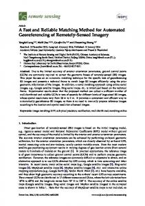
Figure 2: The set of critical junctions (red ticks) delimitating the zone where vehicles are already blocked due to an incident
3. Road-Casting Protocol (RCP) design
Junction (CJ). A CJ is a junction beyond which, a vehicle cannot avoid the broken road segment without turning around and going backwards. Next, the RCP defines a non-deterministic low layer sub-protocol that is responsible for selecting the next forwarder. This latter can be any of the receivers in the neighbourhood of the sender. One forwarder is selected to propagate the message on each of the road segments adjacent to the sender’s current road segment. The selection of the next forwarder is based on two factors: the distance and the link quality. The distance factor considers the position of the receiver vehicle with regard to those of the sender and the next junction. The link quality factor takes into account the signal quality, the channel quality and the packet collision probability.
The word Road-Casting (RC) stands for Road-topology based broadcast. As its name indicates, this protocol consists in sending safety messages to a group of vehicles identified by the road segment they are currently on. 3.1. Assumptions In our work, we focus on the dissemination of safety messages in urban areas. The maximum vehicle velocity is set to 50 km/h in city environment, the relative velocity between two vehicles moving in opposite directions can thus reach up to 100 km/h. We assume that every vehicle is equipped with a navigation system that enables positioning, time synchronization and road identification. This assumption is valid since most of current vehicles are already equipped with this kind of systems. In addition, vehicles are assumed to be equipped with IEEE 802.11p [3] wireless technology and computation capabilities.
4. RCP operating mode In this section, we present a detailed description of the RCP which includes the accurate definition of the RoI for safety messages, and its distributed forwarding mechanism.
3.2. RCP overview The RCP for the dissemination of safety information is designed to achieve a twofold objective; reducing the risk of accidents and reducing their impact on the level of traffic congestion. Starting with this perspective, we tried to answer the questions revealed in section 2: (i) How to define the effective RoI for an emergency message (i.e. control its exact extent in different directions) while minimizing its size (i.e. limit the amount of data included in each transmission)? And, (ii) How to fulfill the requirements related to safety messages dissemination (i.e. short end to end delay, high delivery ratio with a minimum number of retransmissions) while considering relevant and real world conditions (e.g. grey zones, non line-of-sight conditions)? The RCP functioning mode can be summarised in two steps; first, it defines a distributed high layer sub-protocol to determine the effective RoI for each safety message. Each receiver of such a message is only aware of the next step to perform. These receivers decide whether the safety message should be forwarded or not. This decision is based on the incident and the receiver’s location with regard to a point called the Critical
4.1. RoI definition The main purpose of broadcasting safety messages is to inform the drivers early enough, about potential road hazards in order to ensure more efficient reactions. The nature of the safety application can give us a clear idea about how early should the drivers be informed. In fact, this can vary based on the mobility primitives [35] involved in the expected reaction: change lane, stop, change speed, and change both route and destination. Based on these mobility primitives, we have defined three levels for the extent of the emergency message: • Near: in this first case, the message remains within the same road segment. This level is defined for applications that require vehicles to change lanes only such as an emergency vehicle approaching and sending warning messages to ask the vehicles ahead of it, on the same road segment, to free an emergency corridor. • Medium near: in this second case, the message goes a little further (i.e. up to one junction away). This level is defined 5
Table 1: RCP vs. literature solutions: a comparative study
UMB EDB Weighted Persistence IF CODEB LDMB DAZL FairAD RCP
Transmission Reliability ---
End-to-End Delay -++ ++
Overhead
Scalability
--
---
Region of Interest / / /
-+ ++ + ++
++ -+ +
+ ++ -++
-++ + ++
/ / / / -++
for safety applications that require vehicles to change their speeds or to stop such as the case of an intersection collision warning, where a vehicle approaching an intersection can broadcast this information to other vehicles around the corners to request them to slow down or stop, depending on their positions and speed.
the desired destination. As pointed out in section 1, allowing the source vehicle to define the RoI and add it to the safety message is likely to increase the size of this latter as the regions of interest may vary in shape and size according to the road network topology and traffic conditions. On the other hand, letting each vehicle to calculate it independently, based on the GPS information, will most probably increase the dissemination delay of the safety message. This is why we chose to design the RCP based on an algorithm that computes the RoI in a distributed fashion, where each vehicle takes part in the calculation process by only determining its position with regard to one of the CJs. This, therefore, allows defining an accurate RoI while alleviating the load on the radio channel. The distributed algorithm takes into account the direction of the safety message, the shape of the road network and the priority of the message if two competing safety messages were received. The Algorithm 1 summarises the functioning of the RoI definition as designed in RCP. Algorithm 1 describes the distributed process of the RoI definition. BROADCAST () is a function that broadcasts the emergency message along with the current road segment id and the ids of its adjacent road segments, and the direction of the targeted traffic. CONNECTED EDGES () is another function that checks whether a route is available between two road segments using a modified A* algorithm. Finally, the function REMAINING DISTANCE () calculates the distance to which, the emergency message should be further propagated beyond the current CJ and returns true if the message still needs to be propagated and false otherwise. The most important function in this algorithm is CONNECTED EDGES () as it indicates to vehicles whether they are within the RoI or beyond it. In fact, when a car receives an emergency message, it runs a road map connectivity check using a simplified A* algorithm with a limited input. The conventional input for any routing algorithm is a set of nodes which correspond to junctions in our case, and a set of links between those nodes which are represented by road segments in a road map. Running the A* algorithm on the entire city map, at every receiving vehicle can turn up to be very costly in terms of computational resources and can further increase the delay. To
• Far: in this third case, the message travels much further than the two previous cases and traverses several junctions. This level is defined for safety applications involving ”change route” and ”change destination” primitives such as the case of a post crash warning application, where a vehicle involved in a crash will broadcast a warning message a few junctions away so that the receiver vehicles can avoid the road segment where the accident occurred by picking another route. Note that for the first two categories (i.e. near and medium near) the message usually remains within the transmission range of the origin vehicle (i.e. single-hop broadcast), but since we are interested in the multi-hop scheme, the question is to define, for the third category, the number of junctions a message should traverse. To answer this question, we introduce the concept of the critical junction. A Critical Junction (CJ) for an incident that occurred on a road segment A is a junction beyond which vehicles cannot avoid the portion A of the road (if they are moving in the direction towards the accident) without having to turn around and go in the opposite direction. They will, therefore, be blocked till the accident is cleared. Figure 2 is an illustrative example of a road map portion showing the set of the CJs for a given incident location. Let us suppose in this example (i.e. Figure 2) that vehicles are heading from west to east. The red ticks indicate the CJs while the green lines represent the road segments on which, the vehicles can still avoid crossing the broken road. The segments that are considered as blocked are tagged with orange lines whilst a thick red line marks the road segment where the incident occurred. It is clear that if a vehicle, coming from the west, crosses one of the CJs, there will be no alternative route for it to avoid the blocked road segment without going backwards. This is likely to have an impact on the overall traffic congestion level and increases its travel time towards 6
Figure 3: Road map connectivity check performed by each receiver of an emergency message with a possible alternative route for the blue vehicle to avoid the broken road segment
overcome this issue, we used a simplified A* algorithm, with a restrained input. Not only, the simplified A* cuts off its execution if a route between the specified source and destination is found, reducing the cost caused by the callbacks to return the route as an output since it is not needed in our case, but also, the input of the algorithm is minimised as the set of junctions and road segments provided as an input to the A* algorithm is contained within a virtual circle whose radius is the distance between the source and the destination (the current receiver of the emergency message and the source vehicle) as shown if Figure 3.
the driver responsiveness to the received information. This distance is calculated as follows; Dbeyond = M axspeed (GP SRT + DriverRT +
1 ) (1) SM F
such that GP SRT and DriverRT refer to the response time of the GPS and the driver, respectively, while SM F is the safety message frequency. This will determine the exact distance beyond the CJ the safety message should propagate to; and the receivers, which are far enough to react to the received information, can take the necessary measures with lesser manoeuvres. But since the receiver will not necessarily be located exactly on the CJ, the distance left for the message to propagate from the position of the receiver is calculated as follow:
Each receiver of an emergency message, regardless of its direction, route and destination, will check the connectivity of the road map between its current edge and the road segment right after the blocked road. In other words, if there is a route allowing it to avoid the broken link, and still reach the following one while still progressing towards its destination, this means that the receiver is outside of the RoI and it has to stop propagating the message beyond a certain extent. On the other hand, if there are no alternative routes for it to avoid this broken link, this means that the receiver has already crossed a CJ (i.e. entered the orange zone shown in Figure 2). In this case, the vehicle will rebroadcast the message again to vehicles further on the road and on neighbouring road segments allowing it to reach the zone outside of the RoI (i.e. still in the green zone as shown in Figure 2). Once the message has reached a point outside of the critical zone, the receivers in this case will calculate how far yet should this information be forwarded, in order to give the receiver vehicles sufficient time to react efficiently. This distance is calculated based on the maximum allowed speed on the current road segment, Safety Messages transmission Frequency (SMF)(i.e. SMF: the interval between two transmissions of the same safety message by the source vehicle) and some other parameters like an approximation for the GPS response time and
Dremaining = Dbeyond − Dlastjunct
(2)
Where Dlastjunct is the distance between the receiver and the closest CJ to it. This mainly applies in cases where this remaining distance is higher than the transmission range of the sender vehicle (i.e. multi-hop retransmission beyond the CJ). 4.2. Next forwarders definition On a lower layer, the next forwarder selection is of high importance for the performance of any dissemination protocol. In fact, selecting the furthest vehicle to the sender to retransmit a safety message would result in a higher probability of packet loss (due to the grey zone problem for example) while picking a closer node would solve this problem, but at the cost of higher number of retransmissions and consequently a higher end-toend delay, which does not fulfill the requirements of safety applications. One additional problem we identified in most of the literature solutions is the selection of a single forwarder. As depicted in Figure 4, if the selected next forwarder is on the road 7
Algorithm 1 RCP Region of Interest definition Input: N E: Next edges set CE: Edges connected to the current edge D: Directions (incoming, outgoing, both) P : Vector of emergency messages to broadcast, indexed from the highest to the lowest priority A: Age of the message Ec: Current edge Es: Source edge 1: if (current node is the source node) then 2: for (i = 0; P [i] != end; i++) do 3: N E ← CE 4: Es ← Ec 5: BROADCAST (P [i], Es, N E, D) 6: end for 7: else 8: if (A ≤ Amax && Ec in N E) then 9: Connected ← CONNECTED EDGES (Ec, Es + 1) 10: if (Connected == true) then (Eq. 2) 11: Rmn ← REMAINING DISTANCE () 12: end if 13: for (i = 0; P [i] != end && Rmn != f alse; i++) do 14: N E ← CE 15: BROADCAST ((P [i], Ec, N E, D) 16: end for 17: end if 18: end if
A
Figure 4: Dissemination with a single re-transmitter selection under non-line of sight conditions
microseconds, smaller than one time slot. The vehicle with the shortest waiting time will forward the message first. If a vehicle overhears the same message before the end of its waiting time, it will consider it as an acknowledgment for the last message it received and will drop out the retransmission process as depicted in Figure 5. To cope with the highly congested scenarios, we propose to solve the problem of simultaneous transmissions of vehicles having the same retransmission probability by adding a random value in microseconds to the waiting time of vehicles before retransmitting. This value is large enough for one message to propagate through the medium and reach the neighbours, but smaller than one time slot to avoid overlapping transmissions with vehicles having a one-slot-higher waiting time. For example, given a slot time of 9µs, δ ranges between 1 and 8µs. This way, if a vehicle has a Backoff of 5 slots, this random value will not only considerably reduce the chances of it broadcasting at the same moment as another vehicle that have the same slots count, but will also prevent it from broadcasting at the same moment as a vehicle having 6 slots to wait before transmitting. Note that in equation (3), the vehicle having the highest probability will be assigned the shortest Backoff period. This retransmission probability is a weighted sum of two parameters: the Distance factor (D) and the Link Quality factor (LQ). It is calculated as follows;
segment B, the message will most probably stop propagating in road segments A and C, leading to partial notification of the vehicles within the RoI. While designing the RCP, we took care of considering the previously highlighted problems and overcoming them as follows. • Multiple next forwarders: one forwarder is elected on each road segment where the message should propagate (to cope with the single re-transmitter problem); • A vehicle crossing a junction has a higher chance of being selected as the next forwarder to reach more vehicles on side roads (to cope with the non-line of sight problem);
P = (1 − ωP )D + ωP LQ
Where ωP is a weight between 0.5 and 1. This is to give more importance to the link quality, since the emergency messages considered in our study are critical by nature and the reliability of the transmission is one of our main focuses. D and LQ factors are described in the following.
• The selection of each next forwarder is a tradeoff between the distance separating it from the sender, and the link quality (consideration for the grey zones while keeping a short end-to-end delay). The selection of the next forwarders is performed in a decentralised manner, as each receiver of a safety message calculates a probability, which will determine its Backoff period (i.e. waiting time before retransmitting the received message). The RCP Backoff is calculated using the following formula; W T = CW × (1 − P ) + δ
(4)
The Distance factor (D): is a function of the distance between the sender and the potential next forwarder Dr , the next junction and the potential next forwarder Dj , and the next junction to the transmission range Drj , as depicted in Figure 6. The three parameters are thoroughly selected for a better efficiency of the overall performance of the protocol. The combination of these three parameters aims at giving a higher partial priority to vehicles closer to the junction, with the highest priority assigned to the vehicle crossing the junction; but also aims at
(3)
Where W T is the Backoff value, CW is the contention window, P is the calculated probability, and δ is a random value in 8
J
ack.
First retransmission
Figure 6: The distance factor parameters as a metric for the next forwarder selection
Figure 5: The overhearing based acknowledgment mechanism used by the RCP
With this assignment function, the furthest vehicle from the sender is assigned the highest distance factor without taking into account the distance to the next junction.
promoting the fast progress of the emergency message to the other end of the network. In other words, if the junction is far enough from the sender vehicle Dj and Drj are included in the assignment function. On the other hand, if the junction is too close from the sender vehicle, Dj and Drj are not included. Assigning a high distance factor to vehicles close to it would increase their chances to be selected as next forwarders, resulting in more intermediate hops and a slow progress of the emergency message towards the last set of receivers at the other end of the network. This cannot be tolerated in the considered case mainly because of the critical nature of the considered information since a fast dissemination is required. For all the reasons mentioned above and for the sake of efficiency we consider the following two cases.
The output of D is a probability which value is included between 0 and 1 with the lowest value being assigned to the worse positioned vehicle with regard to the sender and the junction locations, and the highest to the best positioned one (i.e. crossing a junction which is far enough from the sender to allow the emergency message to progress rapidly). We noticed that the highest densities are usually observed around junctions, and therefore, a uniform distribution for the Distance factor with regard to the distance parameter only would not be very suitable in city scenarios. For this reason, we elevate the Distance factor value D to the power of n as a way to transform the uniform distribution to a normal distribution and therefore take into account the traffic density parameter, as shown in Figure 7.
• Case 1: if the next junction is further than R2 meters from the sender vehicle (R is the estimated transmission range of the sender vehicle), the closer the vehicle is to the junction, the higher the distance factor assigned to it will be. If the vehicle is either beyond the next junction or crossing it the distance factor is defined as follows: D=
(Dr + (Drj − ωDj )) R
if (Dj ≥ 0)
The Link Quality factor (LQ): is a function of the signal quality (SQ), the channel quality (CQ) and the collision probability (CP ). SQ aims at ensuring the integrity of the received message, CQ is intended to estimate the state of the channel around the receiver before and at the time of the reception of the emergency message, and CP is an estimation of the likelihood of a collision occurrence if the message is forwarded by the current vehicle (vehicle receiving the emergency message). LQ is defined using the following formula;
(5)
Where ω is a weight included between 1 and 2. With this assignment function, the vehicle crossing the junction has the highest distance factor, and as it gets farther from it, the distance factor decreases. If the vehicle didn’t reach the next junction yet, then the distance factor is assigned as follows: D=
(Dr + (Drj − (2 − ω)Dj )) R
if (Dj < 0)
LQ = ωQ SQ + (1 − ωQ )(1 − CP )CQ
(8)
Where ωQ is a weight for the link quality, and is between 0.5 and 1. This is to emphasise that SQ has more impact on the quality of the link than CQ and CP .
(6)
Note that in this sub case, the distance to the junction Dj is a negative value. With this assignment function, the closest vehicle to the junction will be given the highest distance factor.
• The signal quality: is set based on the received signal strength taking into account the Signal to Noise Ratio (SN R) and the relative velocity (to cope with the Doppler effect [36]). A higher SQ is assigned to receivers with a higher RSS and a lower SN R and V . These three conditions combined reduce the probability of errors introduced in the emergency message during the last transmission. First the received signal strength is set to a value S bounded by 1.
• Case 2: if the next junction is less than R2 meters away from the sender vehicle, the distance factor is calculated as follows: Dr D= (7) R 9
Figure 7: The Distance Factor variation vs. the position of the receivers with regard to the junction’s location (n = 4)
Algorithm 2 Next Forwarder Selection Algorithm 1: 2: 3: 4: 5: 6: 7: 8: 9: 10: 11: 12: 13: 14: 15: 16: 17: 18: 19: 20: 21: 22: 23: 24:
(
if (Emergency msg received from app. layer) then Include current position; Initiate CSMA/CA Backoff scheme; Broadcast App Emergency msg; end if if (Emergency msg1 received from Radio Ch.) then if (Already in the queue) then Discard msg1 ; else Include Current Position & Next Road Segments; Compute RCP Retransmission Probability; Initiate RCP backoff scheme; if (Emergency msg2 received from radio Ch.) then if (msg2 == msg1 ) then Discard (Drop off retransmission); else Broadcast Radio Emergency msg1 ; Goto Line 10; end if else Broadcast Radio Emergency msg1 ; end if end if end if
S=
0
if RSS < RSSth
RSS , 1) min( RSS max
if RSS ≥ RSSth
(9)
Where RSS is the received signal strength and RSSth is a threshold below which the received signal is considered too weak. Then, the signal quality is calculated as follows: ( SQ =
max(0, S × (1 − S
1 SN R )
× (1 − V )) if SN R > 0
otherwise (10)
such that the SN R value is the ratio between the signal power and the noise intensity; it is calculated as follows: SN R =
P owersignal P owernoise
(11)
and V is the ratio of the relative velocity between the sender and the potential next hop, to the maximum velocity in urban areas (Vmax = 100 km/h). This latter is the ratio between the relative velocity and the maximum allowed velocity in city scenarios. It is calculated as follows: V = 10
Vrelative Vmax
(12)
Figure 8: The Link Quality Factor variation vs. the distance from the sender for densities of 50 and 100 vehicles/km in both Line-Of-Sight and Non-Line-Of-Sight conditions
the variation of LQ with regard to the distance from the sender vehicle for two different densities (50 veh/km and 100 veh/km) in both Line-Of-Sight and Non-Line-Of-Sight conditions. The different steps involved in the process of selecting the next forwarder of an emergency message are summarised in the Algorithm 2.First, if the current vehicle running the algorithm is the source of the emergency message, then a normal CSMA/CA Backoff is initiated after including the position of the vehicle to the message. This latter is broadcasted after the expiration of the vehicle’s Backoff period. On the other hand, if the emergency message is received from another vehicle in the neighbourhood, the current vehicle checks if it is a duplicated message, which is already in the queue; if so, it is discarded. Otherwise, the RCP Backoff process is launched after including the current position of the vehicle and the next road segments this message should be disseminated to.
• The successful transmission rate is a good indicator for the channel quality as it gives an accurate assessment of the healthiness of the radio channel. A large number of packets lost over the last time window are an indicator that the quality of the channel is mediocre. It is calculated as follows: ( N ST CQ =
N OP
if N OT > 0
0
otherwise
(13)
Where N ST and N OT refer to the Number of Successful and Overall Transmissions during the last time window1 , respectively. • The channel occupancy is the parameter we chose for the collision probability indication. The channel, as observed by the receiver vehicle being busy most of the time during the last time window, indicates that the next transmission might have a lot of competition and is likely to collide with other messages from other transmitter vehicles in the vicinity. It is calculated as follows: CP =
CO TW
5. Performance evaluation In this section, we aim to demonstrate the efficiency of each of the sub-layers composing RCP, namely, the forwarding and the RoI definition mechanisms respectively. The performance evaluation is carried out in two steps: First, we show the gain obtained from using the RCP forwarding mechanism by comparing it to three well known schemes: (i) a simple flooding scheme where each receiver vehicle in the network rebroadcasts the safety message; (ii) a distance based scheme where only the furthest receiver of a safety message is selected to be the next forwarder; and (iii) a link based scheme where only the vehicle with the best link quality, represented by an estimation of the probability of a successful transmission, is selected to be the next forwarder regardless of its distance to the sender vehicle. This probability of successful transmissions is calculated based on the density of vehicles in the surroundings of the receiver as
(14)
Where CO is the Channel Occupancy time and T W is the last time window during which, CP is calculated. The output of LQ is also a probability which value is included between 0 and 1 with the lowest value being assigned to the vehicle that shows the worst channel conditions. Figure 8 shows 1 N ST and N OT are calculated over a floating time window T W , fixed in length.
11
(a) Algiers map
(b) Manhattan grid
Figure 9: A road map portion of (a) the city of Algiers and (b) Manhattan, New York, converted to SUMO format and used in the simulations
Table 2: Simulation parameters
a vehicle with the highest number of neighbours has the least chances to be selected as the next forwarder and vice versa. To represent the road network, we chose a 4km2 Manhattan Grid with a 500 meters distance between intersections. Next, we show the benefits of the RoI definition and its accuracy using RCP. We compare it to the general assumption in the literature, which is a circular RoI. Two scenarios of two different road patterns were tested (road maps imported from OpenStreetMap2 ) for this second part of simulations. They consists in a 2 km2 Manhattan Grid road portion (Figure 9(b)), and a 1 km2 portion of the city of Algiers, Algeria (Figure 9(a)).
Physical Layer
Link Layer
5.1. Simulation setting To prove the efficiency of our forwarding mechanism and RoI definition and their effectiveness, we implemented and tested RCP using the NS-33 simulator with IEEE802.11p enabled. We took special care of selecting the most realistic and representative models for vehicular communications. These radio communications are not easy to model especially in urban areas where shadowing and fading effects have severe impact on the performance of the communications. In fact, it is shown in [37] that the Two Ray Ground propagation model, used in most of the literature solutions, is not suitable for inter vehicle communication simulations. Corner, is a channel model that addresses the non-line of sight problem, observed in city based scenarios, by classifying vehicles based on their positions on the road and the number of corners separating them. The evaluation results of this model show a very high level of accuracy. We refer the reader to [10] and [38] for more specifications about this model. For our simulations, we used an enhanced version of Corner [38], which considers the multi path fading in addition to the shadowing caused by buildings. We ported the Enhanced Corner from OMNet++4 simulator, where it was originally implemented by the authors, and adapted it to NS-3 for our simulation. The mobility of vehicles is another crucial element that plays a key role in the overall performance of any VANET protocol
Link Layer (RCP MAC)
Transport Layer (RCP ROI) Scenario
Frequency band Bandwidth Transmission range Tx Power Receiver sensitivity Noise level Bit rate CW Time slot ω (Distance Factor) Time window RSSth Vmax ωQ (Send Probability) δ (Waiting Time) GP SRT DriverRT Agemax Directions Data message size Broadcast frequency
5.9 GHz 10 MHz 260 m 19.03 dBm -45 dBm -105 dBm 6 Mbits/s [15, 1023] 13 µs 1.5 10sec -40 dBm 100 km/h 0.5 [1, 11] µs 1sec 3sec 100 milliseconds {In, Out, Both} 100 bytes 1Hz
or application. We used SUMO5 , a traffic simulator, to generate the traffic demand on real road networks imported from Open Street Map. We also used HINTS [39], a platform that allows SUMO and NS-3 to run simultaneously and exchange information relative to the mobility of vehicles. The complete list of simulation parameters is given in Table I. 5.2. Forwarding mechanism evaluation To prove the efficiency of the RCP forwarding mechanism against the three above-mentioned schemes namely, the flooding, the distance based and the link based approaches, we disabled the RoI definition and set our protocol to reach the maximum number of vehicles (in accordance with the two other schemes). The evaluation metrics considered are (i) the Packet
2 http://www.openstreetmap.org 3 http://www.nsnam.org 4 http://www.omnetpp.org
5 http://www.sourceforge.sumo.org
12
80
20
End-to-End Delay (ms)
25
Packet Delivery Ratio (%)
100
60
40
15
10
20
0
RCP Dist. based Link based Flooding
5 RCP Dist. based Link based Flooding 75
0 125
175
225 Density (veh/km2)
275
325
375
75
125
(a) Packet Delivery Ratio
175
225 Density (veh/km2)
275
325
375
(b) End-to-End Delay
10000
Overhead (bytes)
8000
6000
4000
2000 RCP Dist. based Link based Flooding
0 75
125
175
225
275
325
375
Density (veh/km2)
(c) Overhead Figure 10: Impact of vehicles density on the efficiency of the forwarding mechanism of safety messages: RCP vs. distance based forwarding, link based forwarding and flooding
Delivery Ratio, (ii) the End-to-End Delay and (iii) the communication Overhead. We ran the simulation for 1200 seconds under various vehicles densities ranging from 75 to 375 vehicles per km2 . The Packet Delivery Ratio (PDR), illustrated in Figure 10(a) is obtained by calculating the ratio between the number of transmitted packets and the number of received packets as follows:
hicles, the PDR for the flooding stabilises as a consequence of the large number of failed transmissions in this scheme. In fact, at a very high density level, the number of collisions increases exponentially. This retrains the progress of the packets, and consequently the information will reach closer vehicles only (at a limited number of hops from the source). The End-to-End (E2E) Delay shown in Figure 10(b) is the time in milliseconds, needed for a packet sent by the source to cross the network and reach its final receiver. The results shown in Figure 10(b) are an average of delays for the full duration of the simulation. Even though the distance-based approach was designed to promote the progress of the packet to its destination, RCP does not perform worse. With 2 millisecond difference at a density of 75 vehicles, RCP performs better with an E2E delay of 12 milliseconds at a density of 375 vehicles. This value decreases and stabilises for the flooding approach, at a density of 225 vehicles per km2 . This is due to the same reasons highlighted above (PDR discussion) since the packets will travel less and less distances from the source because of higher packet loss. The link based on the other hand performs worse than the distance based and RCP mainly because of the higher number of intermediate vehicles, the packets need to hop in, in order to reach their destinations. Note that we are far from the
N umber of transmitted packets N umber of successf ully received packets (15) A packet is considered as received if it reaches one or more neighbour vehicles other than the sender. On the other hand, if none of the neighbour vehicles receives the emergency message, the packet is considered as lost. At a density of 75 vehicles per km2 , we observed 96% of successful transmissions for the RCP against 80 %, 70% and 60% for the link based, the distance based and the flooding schemes, respectively; with the link based scheme performing slightly better than the distance based. Moreover, this number drops with the increase of vehicles density in these three approaches, while it remains stable for the RCP scheme (between 96% and 98% of successful transmissions). We also notice that at a density level of 225 veP DR =
13
100 milliseconds delay limit requirement, defined in [40] for safety messages dissemination. The overhead, depicted in Figure 10(c), is represented by the overall amount of data in bytes inserted in the network for one end-to-end transmission. This metric aims at measuring the amount of data generated by a single emergency message disseminated in the network. The results were obtained by calculating the average overhead for the full simulation duration. While the flooding scheme congests the communication network with less accuracy in terms of PDR and E2E delay, we observed very similar amounts of data inserted in the network for RCP and the distance based schemes from densities between 75 and 275 vehicles per km2 . with more overhead generated by the link based scheme (3800 Bytes in a density of 75 veh/km2 up to more than 8000 Bytes in the highest density). This was also expected for the same reasons mentioned in the E2E discussion, since packets need to hop in more intermediate vehicles generating, therefore, a higher number of messages in the network. By selecting multiple forwarders on different road segments, we took the risk of overloading the network compared to a distance-based scheme where only one forwarder is selected. But we compensate this with the accuracy of our transmissions. In other words, our scheme needs approximately one packet per retransmission while the distance-based approach requires nearly two packets per retransmission (see the Packet Delivery Ratios in Figure 10(a)). We also notice that beyond 275 vehicles per km2 the overhead stabilises for RCP. This is mainly because at a certain level of congestion (vehicles density), the protocol does not need more retransmissions to reach all the vehicles in the network, but reaches more vehicles in each retransmission instead. Similarly, the stabilisation of the overhead in the case of the simple flooding is explained by the high number of collisions as a result of the high density of vehicles. In fact, after a density of 125 vehicles per km2, the channel reaches a point way beyond its full capacity and every transmission of an emergency message collides with another transmission from another neighboring vehicle. In other words, the emergency message only travels a few hops away from the source vehicle and the number of emergency messages inserted in the network stabilises. In the considered case of urban scenarios, the concentration of vehicles is often noticed at intersections. Giving more retransmission priority for vehicles close to intersections allows not only to reach more vehicles on adjacent roads to the source, but also ensures that there is always at least one vehicle to further forward the message.
carried by the safety message) but will not receive it. The extra receivers are vehicles outside the RoI (which do not need the safety message) but will receive it anyway. We call the ideal case, the scenario where all the vehicles inside the RoI receive the safety message with no extra receivers (0% of missed vehicles and 0% of extra receivers). We obtained the values of the ideal case by retrieving the occupancy of each road inside the RoI. The metrics considered are (i) the accuracy of the RoI definition, (ii) the ratios of extra receivers and missed vehicles, (iii) the overall number of receiver vehicles, and (iv) the deviation from the ideal case. We have simulated an accident on one of the road segments; the crashed vehicle broadcasts a warning message (i.e. safety message) with a frequency of 1Hz. The diameter of the circular RoI is set to 500 meters around the accident location. We ran the simulations for 600sec under varying vehicle densities. The ratio of extra receivers is calculated with the following formula: P extra recv (16) Ratio of extra receivers = P recv ideal While the ratio of the missed vehicles is calculated as follows: P miss veh (17) Ratio of missed vehicles = P recv ideal P such that recvPideal refers to the total number of receivers in the ideal case, miss veh is the number of missed vehicles P and extra recv represents the number of extra receivers. The results for the Manhattan grid scenario show that the two approaches perform perfectly well and show 0% of missed vehicles (i.e. no vehicle inside the RoI is missed for both RCP and Circular cases). This is due to relatively small RoIs in this case, compared with the second scenario’s RoI (up to one kilometre long). In fact, two hops are sufficient to cover the entire RoI since one road segment in Manhattan is approximately 250 meters long, and a bidirectional antenna can reach up to twice the transmission range which is estimated to 260 meters in city environments (according to the empirical measures done in [41]). The graph is not shown for the sake of brevity. While the circular RoI performs perfectly and as good as the RCP RoI in the Manhattan grid scenario in terms of missed vehicles, it performs much worse in a more complex and asymmetric road topology. Figure 11 shows up to 50% of missed vehicles for the circular RoI case against 7% of missed receivers in low densities (worst case scenario). On the other hand, the RCP RoI performs much better than the circular RoI in different road patterns (both scenarios) in terms of extra receivers. Figure 12 shows the substantial gain that we obtain from using the RCP RoI with 12(a) for the Manhattan Grid scenario and 12(b) for Algiers Scenario. These results show for the Manhattan grid scenario up to 112% of extra receivers for the circular RoI against 14% as a maximum for the RCP RoI; and for Algiers map scenario, up to 140% of extra receivers in the circular RoI scheme against 11% as a maximum in the RCP RoI scheme.
5.3. RoI definition evaluation To show the gain we obtain when applying our RoI definition technique, we compared it to a circular RoI using the RCP forwarding mechanism for both schemes. We run the simulations for two different road topologies: 2 km2 of the well known Manhattan grid map, shown in Figure 9(b); and a 1 km2 more complex road network representative of an old city, shown in Figure 9(a). The metrics used for the evaluation are based on the numbers of missed vehicles and extra receivers. Missed vehicles are vehicles inside the RoI (which need the information 14
The overall number of received messages in the network, as illustrated in Figure 13, shows the overhead caused by the out of scope transmissions represented by the number of received messages with 13(a) for Manhattan Grid scenario and 13(b) for Algiers map scenario. We compared the RCP and the circular RoI schemes with the ideal case and the results show a significant advantage of the RCP scheme over the circular RoI with a negligible overhead for the first one compared to the ideal scheme and up to 100% of overhead for the second one in both road patterns. The accuracy of the RoI definition, shown in Figure 14, is obtained with the following formula: P P recv ideal − miss veh P (18) RoI accuracy = recv ideal
100
RCP Circular
Missed vehicles (%)
80
60
40
20
0 25
50 75 Density (veh/km2)
100
Figure 11: The ratio, under different vehicle densities, of vehicles located inside the RoI which did not receive the emergency message (Algiers map only)
Using this definition of the accuracy, both the circular RoI and the RCP RoI would have the highest values in the Manhattan grid scenario as the ratio of missed vehicles is 0% for both schemes. The graph representing the accuracy for the Manhattan grid scenario is not shown for the sake of brevity as both schemes show 100% of accuracy. On the other hand, the asymmetric road pattern shows a substantial difference between the two schemes as the RCP RoI performs much better than a circular RoI in terms of accuracy. At a density of 25 vehicles, the RCP shows an accuracy of more than 92% while the Circular RoI definition achieves approximately 70% of accuracy. In addition to this, while the Circular RoI accuracy decreases in more dense networks, the RCP RoI accuracy gets better. Finally, to give a better representation of our results obtained from the two different scenarios with two different road patterns, we introduce the deviation metric (Figure 15) as the percentage of which, each scheme deflects from the ideal case. In other words, the amount of diversion of each scheme from the ideal case. The deviation values shown in Figure 15 were obtained using the following formula:
6. Conclusion and Future Work
In this paper, we presented the Road Casting Protocol (RCP), a cross layer dissemination protocol for safety messages in citybased VANETs scenarios. Our goal to alleviate the load on the network of vehicles was achieved by designing a distributed algorithm for an accurate Region of Interest (RoI) definition. An efficient forwarding mechanism was also designed to guarantee a high level of reachability and a short dissemination delay, in accordance with VANETs safety applications’ requirements. Simulations were conducted using realistic channel and mobility models. The obtained results have proven the efficiency of our protocol and highlighted the substantial benefits that VANETs can gain when using it. First, we have evaluated the forwarding mechanism of our protocol separately to justify our design choice; then, the entire protocol was evaluated and compared with the most common approach in the literature. Future works will focus on studying the impact of beacons P P P recv ideal − ( miss veh + extra recv) up-to-dateness and the impact of channel congestion generated P Deviation = 100 − recv ideal by these beacons on the performance of emergency messages (19) dissemination. Also, on designing novel approaches to enable accurate definition of the RoI applicable for other application Figure 15(a), representing the deviation for the Manhattan grid classes with different requirements. scenario, reveals the supremacy of RCP RoI compared to the circular RoI, with a deviation of up to 112% in this latter against 15% only in the former’s worst case (i.e. density of 100 veAcknowledgment hicles). As for the Algiers map scenario represented in Figure 15(b), the results show even larger gap with a deviation of 195% This work was supported, in part, by Science Foundation for the circular RoI against 14% only for the RCP RoI at the Ireland grant 10/CE/I1855 to Lero - the Irish Software Engihighest density of 100 vehicles per km2 . neering Research Centre (www.lero.ie). The Earth and Natural To conclude, we can say that we achieved a twofold goal usSciences Doctoral Studies Programme is funded under the Proing the RCP RoI: the first one being the accurate definition of gramme for Research in Third-Level Institutions and co-funded this geographical area. Thanks to this, more vehicles that need under the European Regional Development Fund an incident’s emergency message are reached. This is a crucial condition in a critical system that aims at enhancing the safety References of the road users. The second achievement is reducing the overhead on the radio channel allowing more data to be carried by [1] [C. D. Wang and J. P. Thompson, “Apparatus and Method for Motion Dea VANET. This is also a very important issue; mainly because tection and Tracking of Objects in a Region for Collision Avoidance Utiof the large spectrum of safety applications expected to be delizing a Real-Time Adaptive Probabilistic Neural Network,” U.S. patent no. 5,613,039, 1997.] ployed and the limited bandwidth dedicated to this end. 15
160
RCP Circular
140
140
120
120
100
100
Extra receivers (%)
Extra receivers (%)
160
80
60
RCP Circular
80
60
40
40
20
20
0
0 25
50 75 Density (veh/km2)
100
25
(a) Manhattan grid
50 75 Density (veh/km2)
100
(b) Algiers map
Figure 12: The ratio, under different vehicle densities, of vehicles located outside the RoI which did receive the emergency message
70
70
Ideal RCP Circular
Ideal RCP Circular
60
60
Total Number of Messages
Total Number of Messages
50 50
40
30
40
30
20
20
10
10
0 25
50
75
100
25
Density (veh/km2)
50
75
100
Density (veh/km2)
(a) Manhattan grid
(b) Algiers map
Figure 13: The overall number of messages exchanged, under different vehicle densities, for one emergency message emission, for the circular RoI and the RCP RoI scheme compared with the ideal case
200
RCP Circular
180
180
160
160 Deviation from the ideal case (%)
Deviation from the ideal case (%)
200
140 120 100 80 60
140 120 100 80 60
40
40
20
20
0
RCP Circular
0 25
50 75 Density (veh/km2)
100
25
(a) Manhattan grid
50 75 Density (veh/km2)
100
(b) Algiers map
Figure 15: The percentage of deviation from the ideal case under different vehicle densities: circular RoI vs. RCP RoI
16
100
(MHVB),” in Proc. IEEE Int’l Conf. on ITS Telecomm. (ITST), Jun. 2006 [17] S. Khakbaz and M. Fathy, “A reliable method for disseminating safety information in vehicular ad hoc networks considering fragmentation problem,” in Proc. IEEE Int’l Conf. on Wireless and Mobile Communi- cations (ICWMC), Jul. 2008 [18] H. Lundgren, E. Nordstr¨om and C. Tschudin, “The Gray Zone Problem in IEEE 802.11b based Ad hoc Network, ” in ACM Mobile Computing and Communications Review(SIGMOBILE), Vol. 6, No 3, Sep. 2002 [19] N. Wisitpongphan, O. K. Tonguz, J. S. Parikh, P. Mudalige, F. Bai, and V. Sadekar, “Broadcast storm mitigation techniques in vehicular ad hoc networks,” in IEEE Wireless Commun., vol. 14, no. 6, pp. 84-94, Dec. 2007. [20] S. Panichpapiboon and G. Ferrari, “Irresponsible forwarding,” in Proc. IEEE Int’l Conf. on ITS Telecomm. (ITST), Oct. 2008 [21] R. W. Yeung, “Network coding: A historical perspective,” in Proc. IEEE, vol. 99, no. 3, pp. 366-371, Mar. 2011. [22] L. Li, R. Ramjee, M. Buddhikot, and S. Miller, “Network coding-based broadcast in mobile ad hoc networks,” in Proc. IEEE Conf. on Computer Comm. (INFOCOM), May 2007 [23] Y. T. Tseng, R. H. Jan, C. Chen, C. F. Wang, & H. H. Li. “A vehicledensity-based forwarding scheme for emergency message broadcasts in VANETs.” In IEEE 7th International Conference on Mobile Adhoc and Sensor Systems (MASS), 2010. pp. 703-708. [24] R. Meireles, P. Steenkiste and J. Barros, “DAZL: Density-Aware Zonebased Packet Forwarding in Vehicular Networks,” in IEEE Vehicular Networking Conference (VNC), Nov. 2012 [25] R. S. Schwartz, A. E. Ohazulike and C. Sommer, “Fair and Adaptive Data Dissemination for Traffic Information Systems” in IEEE Vehicular Networking Conference (VNC), Nov. 2012 [26] C. Campolo, A. Molinaro, A. Vinel, & Y. Zhang, “Modeling EventDriven Safety Messages Delivery in IEEE 802.11 p/WAVE Vehicular Networks.” in IEEE Communications Letters, 17(12), 2013 [27] M. Rondinone, and J. Gozalvez. “Distributed and real time communications road connectivity discovery through vehicular ad-hoc networks. In 13th International IEEE Conference on” Intelligent Transportation Systems (ITSC), 2010. [28] M. Rondinone, and J. Gozalvez. “Contention-based forwarding with multi-hop connectivity awareness in vehicular ad-hoc networks.” In Computer Networks 2013. pp. 1821-1837. [29] K. Ibrahim, M. C. Weigle, and M. Abuelela. “p-IVG: Probabilistic intervehicle geocast for dense vehicular networks.” in IEEE 69th Vehicular Technology Conference (VTC) Spring 2009. [30] T. Atechian, and L. Brunie. “DG-CastoR for query packets dissemination in VANET.” In 5th IEEE International Conference on Mobile Ad Hoc and Sensor Systems. (MASS) 2008. [31] H. P. Joshi, M. L. Sichitiu, and M. Kihl. “Distributed robust geocast multicast routing for inter-vehicle communication.” In Proceedings of WEIRD workshop on WiMax, wireless and mobility. 2007. [32] S. Allal, and S. Boudjit. “Geocast routing protocols for vanets: Survey and guidelines.” In Sixth International Conference on Innovative Mobile and Internet Services in Ubiquitous Computing (IMIS), 2012. [33] Karagiannis, G., Altintas, O., Ekici, E., Heijenk, G., Jarupan, B., Lin, K., & Weil, T. “Vehicular networking: A survey and tutorial on requirements, architectures, challenges, standards and solutions.” In Communications Surveys & Tutorials, IEEE, 13(4), 584-616. [34] Willke, T. L., Tientrakool, P., & Maxemchuk, N. F. “A survey of intervehicle communication protocols and their applications.” In Communications Surveys & Tutorials, IEEE, 11(2), 3-20. [35] CAR 2 CAR Communication Consortium Manifesto version 1.1. Technical report, (C2C-CC), Aug 2007 [36] T.P. Gill “The Doppler effect: An introduction to the theory of the effect,” in Logos Press (London), 1965 [37] C. Sommer and F. Dressler, “Using the Right Two-Ray Model? A Measurement-based Evaluation of PHY Models in VANETs,” in Proc. ACM MobiCom, Sep. 2011. [38] A. Mukunthan, C. Cooper, F. Safaei, D. Franklin and M. Abolhasan, “Studying the Impact of the CORNER Propagation Model on VANET Routing in Urban Environments,” in IEEE Vehicular Technology Conference (VTC Fall),Sep. 2012 [39] S. Zemouri, S. Mehar and S.M. Senouci, “HINTS: A novel approach for realistic simulations of vehicular communications,” in Global Informa-
Accuracy (%)
80
60
40
20
RCP Circular
0 25
50 75 Density (veh/km2)
100
Figure 14: Impact of vehicles density on the accuracy of the RoI definition: RCP scheme RoI vs. circular RoI (Algiers map only)
[2] Draft ETSI EN 302 663 V1.2.0 Intelligent Transport Systems (ITS); Access layer specification for Intelligent Transport Systems operating in the 5 GHz frequency band European Standard, November 2012 [3] 802.11p-2010 - IEEE Standard for Information technology– Local and metropolitan area networks– Specific requirements– Part 11: Wireless LAN Medium Access Control (MAC) and Physical Layer (PHY) Specifications Amendment 6: Wireless Access in Vehicular Environments. [4] ETSI TS 102 687 V1.1.1, Intelligent Transport Systems (ITS); De- centralized Congestion Control Mechanisms for Intelligent Transport Systems operating in the 5 GHz range; Access layer part, July 2011 [5] A. Autolitano, C. Campolo, A. Molinaro, R.M. Scopigno, & A. Vesco, “An insight into Decentralized Congestion Control techniques for VANETs from ETSI TS 102 687 V1. 1.1, ” In IFIP/IEEE Wireless Days (WD), Nov. 2013. pp. 1-6. [6] S. Panichpapiboon and W. Pattara-atikom, “A Review of Information Dissemination Protocols for Vehicular Ad Hoc Networks,” in IEEE Communications Surveys & Tutorials, Vol. 14, No. 3, pp. 784-798, Aug. 2012 [7] Q. Yang, & L. Shen, “A Multi-hop Broadcast Scheme for Propagation of Emergency Messages in V ANET,” in IEEE International Conference on Communication Technology (ICCT), Nov. 2010, pp. 1072 - 1075. [8] N. N. Nakorn, & K. Rojviboonchai. “DECA: Density-aware reliable broadcasting in vehicular ad hoc networks.” In IEEE International Conference on Electrical Engineering/Electronics Computer Telecommunications and Information Technology (ECTI-CON), 2010. [9] E. Fitzgerald, & B. Landfeldt. “A system for coupled road traffic utility maximisation and risk management using VANET.” In the 15th International IEEE Conference on Intelligent Transportation Systems (ITSC), 2012 [10] E. Giordano, R. Frank, G. Pau and M. Gerla, “CORNER: a Realistic Urban Propagation Model for VANET,” in Wireless On-demand Network Systems and Services (WONS), Feb. 2010 [11] C. Sommer, S. Joerer, M. Segata , O. Tonguz, R. L. Cigno, and F. Dressler, “How shadowing hurts vehicular communications and how dynamic beaconing can help”, In INFOCOM, April 2013. [12] S. Zemouri, S. Djahel, and J. Murphy. “Road-Casting: A New Distributed Dissemination Protocol for Safety Messages in Urban Areas”. in The 2013 IEEE Vehicular Networking Conference(VNC), Boston, USA, Dec. 16-18, 2013. [13] T. J¨ochle, B. Wiedersheim, F. Schaub and M. Weber, “Efficiency Analysis Of Geocast Target Region Specifications For VANET Applications,” in IEEE Vehicular Networking Conference (VNC), Nov. 2012. ¨ uner, and U. ¨ uner, “Urban multi- hop ¨ Ozg¨ [14] G. Korkmaz, E. Ekici, F. Ozg¨ broadcast protocol for inter-vehicle communication systems,” in Proc. ACM Int’l Workshop on Vehicular Ad Hoc Networks. (VANET), Sep. 2004 [15] D. Li, H. Huang, X. Li, M. Li, and F. Tang, “A distance-based directional broadcast protocol for urban vehicular ad hoc network,” in Proc. IEEE Int’l Conf. on Wireless Comm., Networking and Mobile Computing (WiCom), Sep. 2007 [16] T. Osafune, L. Lin, and M. Lenardi, “Multi-hop vehicular broadcast
17
ria) in February 2007 and June 2004, respectively. The research interests of Soufiene Djahel fall under the field of wireless networking with main focus on communication protocols design and security in MANETs, WMNs, VANETs and WSNs, Intelligent Transportation Systems including dynamic route planning algorithms and data collection techniques. He is member of IEEE and reviewer of its major conferences and journals in wireless networking and security. He has also served on the TPC of some conferences including IFIP wireless days, IEEE WCNC, IEEE ICC, IEEE Globecom and IEEE IWCMC.
tion Infrastructure and Networking Symposium (GIIS), Dec. 2012 [40] VSC-A final report, US Department of Transport, 2011 [41] C. Sommer, D. Eckhoff, R. German and F. Dressler. “A computationally inexpensive empirical model of IEEE 802.11 p radio shadowing in urban environments”. In Wireless IEEE in On-Demand Network Systems and Services (WONS), Bardonecchia, Italy, Jan 2011
Sofiane Zemouri received the B.S. degree in computer science from the University of Science and Technology Houari Boumediene, Algiers, Algeria, and the M.S. degree in telecommunication and computer science from University of Versailles Saint-Quentin-en-Yvelines, Versailles, France and Telecom ParisTech, Paris, France. He is currently working towards the Ph.D degree in computer networks performance and engineering with the Department of Computer Science and Informatics at University College Dublin, Ireland. His research interests include performance and reliability of communication systems in Vehicular Ad Hoc and Sensor Networks.
John Murphy is an Associate Professor in Computer Science and Informatics at University College Dublin. He got a first class honours degree in electronic engineering (B.E.) in 1988 from the National University of Ireland (UCD), an M.Sc. in electrical engineering from the California Institute of Technology in 1990 and a Ph.D. in electronic engineering from Dublin City University in March 1996. He is an IBM Faculty Fellow, a Senior Member of the IEEE, a Fellow and Chartered Engineer with Engineers Ireland, and a Fellow of the Irish Computer Society. For many years he held an academic part-time position at the Jet Propulsion Laboratory in Pasadena, and acted as a consultant to the US Department of Justice. Prof. Murphy is an associate editor for both IEEE Communications Letters Journal, a member of the Editorial Board for the IET Communications (formerly IEE Proc Communications), and an associate editor for Telecommunications Systems Journal. He was the guest editor (along with Prof. Perros) for a special issue of IET Communications on Optical Burst and Packet Switching in 2009. He has published over 100 peer-reviewed journal articles or international conference full papers in performance engineering of networks and distributed systems and has been awarded over 20 competitive research grants (over 5 million euro). He has supervised 13 Ph.D. students to completion.
Soufiene Djahel is a research fellow at University College Dublin and member of wireless networking group of PEL since February 2012. In 2011, he was a postdoc fellow at ENSIIE where he was involved in a research project aiming at designing communication protocols for Hybrid Sensor and Vehicular Networks (HSVNs). He got his Ph.D degree in computer science in December 2010 from university of Lille1 (Lille, France). During his Ph.D, he was working on security issues at MAC and Routing layers in wireless multi-hop networks. Prior to that, he spent 6 months at INRIA NORD Europe research center as an engineer researcher. He received a Magister degree with majors in networking and distributed systems and an Engineering degree in computer science from Abderrahmane-mira University (Bejaia, Algeria) and Badji-Mokhtar University (Annaba, Alge-
18