A Fast Shielding Effectiveness Calculation of Rectangular Enclosures with Arbitrary Shape Apertures M. A. Khorrami1, P. Dehkhoda2, R. Moini3 and S. H. H. Sadeghi4 1, 2, 3, 4
Electromagnetic Research Laboratory of Amirkabir University of Technology, Tehran, Iran.
[email protected],
[email protected],
[email protected],
[email protected].
Abstract – A fast method of moments (MoM) solution of surface electric field integral equation (EFIE) is employed to evaluate the electromagnetic wave coupling inside metallic enclosures, due to presence of arbitrary shape slots. In this paper, we propose an appropriate numerical integration technique in order to reduce the MoM impedance matrix calculation time without compromising accuracy. The technique is used to compute integrals resulting from MoM for the frequencies above the cavity first resonance. Within this frequency range, the wave penetration inside the enclosure is high and so one can avoid unnecessary high accuracy integrations. Regarding this new technique, the shielding effectiveness of an enclosure is evaluated efficiently in a wide range of frequency. The accuracy of the method is demonstrated by a number of examples.
the metallic surface of the cavity. Multilevel fast multipole method (MLFMM) [4], and adaptive cross approximation algorithm (ACA) [5], are then used to accelerate the MoM solution. Finite-difference time domain (FDTD) [7], [8] and finite-element method (FEM) [9] are also employed to calculate the SE. In [10], a modal moment method is proposed to determine the shielding effectiveness. In this paper, the electric currents on the metallic surface of the enclosure, obtained from the MoM, are used to calculate the electric field within the scatterer. In order to accelerate MoM impedance matrix fill time, we propose an efficient numerical integration technique based on barycentric subdivision method [11].As will be illustrated, this technique is accurate, fast, and also it allows the shifted resonance frequencies of the perforated enclosure to be determined correctly.
Keywords: Electromagnetic Compatibility (EMC); method of moments (MOM); Impedance Matrix; Numerical Modeling; Shielding effectiveness
1. Introduction In the last few years, there has been a growing interest within the electronic industry regarding the problems related to the usage of shielding equipments. Metallic enclosures are frequently used to reduce the electromagnetic emission or to improve the immunity of electronic equipments against interfering electromagnetic waves. The ability of a shielding enclosure is usually characterized by its shielding effectiveness (SE), defined as the ratio of field strengths in the presence and absence of the enclosure. SE is primarily affected by the wave penetration through apertures and slots used to accommodate visibility, ventilation or access to interior components. Several methods have been developed for determining the SE of metallic enclosures with apertures on the walls using both analytical and numerical approaches. Many of analytical methods are derived from Bethe's theory of diffraction through holes [1] and are applied only to electrically small apertures. The numerical evaluation of the SE of the metallic enclosures may be obtained to a high degree of accuracy by using various computational methods. In [2] and [3], SE is characterized by surface equivalence theorem [6] and the method of moments (MoM). In [4] and [5], the moment method is used to solve EFIE on
1-4244-1435-0/07/$25.00©2007 IEEE
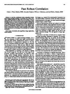
2. Solving Electric-Field Integral Equation Consider a rectangular metallic cube with dimensions (a × b × c) as illustrated in Fig. 1. A rectangular aperture with length L and width W is located at the center of the cavity front face (i.e., z=0 plane). The EFIE is solved numerically in order to evaluate the coupled wave in the center of the enclosure which is exposed to an incident plane wave (as Fig. 1). The field values computed by the EFIE for noncompletely enclosed scatterers like aperture perforated cavities are correct even at the resonance frequencies [4]. a
c b L W
y xc
Ei Hi
yc z
x
Incident plane wave
Figure 1: Geometry of the problem.
i
s
Suppose E is the incident field and E is the scattered field produced by electric currents on the cavity surface, which can be described as
E = − jω A − ∇φ . (1) Where, A and φ are the magnetic vector and s
electric scalar potentials, as defined in [6]. The continuity of the tangential component of total electric field at any point on the metallic surface of the structure, provides the well-known EFIE − E tan i = ( − j ω A − ∇φ ) tan . (2) We solved (2) with the aid of the method of moments and the well-known Rao-Wilton-Glisson (RWG) basis functions [12]. RWG basis function for each edge of triangular mesh is defined as ln + + 2A + ρ n , r in T n n l f n ( r ) = n− ρ − n , r in T − n 2A n 0 otherwise
A
where,
±
,
(3)
is the area of triangle T
n
length of nth edge and
ρ
±
±
n
, l n is the
is the position vector
n
±
defined with respect to the free vertex of T n . Using the Galerkin technique, we solve two potential integrals of the form A
±
µ = 4π
mn
φ ± mn = −
∫
S
f n ( r ′)
1 4π jωε
∫
e − jkR
±
m
R ±m
∇′S • f n ( r ′ )
S
dS ′
(4)
e− jkR R
±
±
m
dS ′ .
(5)
m
Where, m is the observation point, n is the source triangle, S is the surface of nth triangle,
R ± m = r c ± m − r ′ and r c ± m is mth triangle center. About 90% of the CPU time required for the filling of the MoM impedance matrix for the RWG basis function is spent on the calculation of the surface integrals (4) and (5), which can be evaluated in a number of ways, [13]-[16]. The singularity of the freespace Green‘s function is integrable in 2D using Gaussian formulas [17], but the accuracy of the Gaussian formulas is reduced if this singularity is retained. Therefore, singularity extraction of (4) and (5) is performed
∫ S
e− jkR R
±
±
m
m
dS ′ =
1
∫R S
±
dS ′ + m
∫ S
e− jkR R
±
±
m
m
−1
dS ′ ,
(6)
∫
fn ( r ′)
e − jkR R
S
±
e
∫
+ fn ( r ′) ×
±
m
dS ′ =
m
fn ( r ′) R±m
S
− jkR ± m
R±m
S
∫
−1
dS ′
.
(7)
dS ′
We used analytic integrals in [13] to compute the singular terms and the Gaussian formulas for the nonsingular terms of (6) and (7). This method will give us an accurate solution but the CPU time required is too much for calculating the SE of large enclosures in wide range of frequencies. In order to reduce the calculation time, we used the integration method mentioned in [11], which uses barycentric subdivision of an arbitrary triangle. We evaluate integrals in (4) and (5) by barycentric subdivision method within the frequency ranges above the first resonance of the cavity. For barycentric subdivision integration, any primary triangle is divided into nine equal small sub-triangles. Further, we assume that the integrand is constant within each small triangle, for example, integral in (5) can be calculated as
∫ S
e − jkR
±
m
R±m
where R
c±
m
9
A dS ′ = m 9
∑
k =1
= r c ± m − rk′
c
e − jkR
c±
m
Rc±m
,
(8)
and rk′ , k=1,…, 9, are c
the midpoints of nine sub-triangles and Am is mth subtriangle‘s area. Although, this method doesn’t have good accuracy in low frequency ranges where the SE of the enclosure is high, it will give good results with much less CPU time at frequencies above the first resonance of the cavity where the SE is not high.
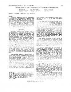
3. Analysis Validation Consider a 30 × 12 × 30 cm rectangular cavity with a rectangular aperture of length L=20 cm and of width W=3 cm. The electric field shielding effectiveness at the enclosure center point is calculated using MoM. Fig. 2 shows a comparison between results of MoM with the exact integration method and the proposed technique. The figure also includes the regenerated curve of Modal MoM, [10]. As can be seen there is a good agreement between conventional EFIE solution and our method. Also, both EFIE curves are close to Modal MoM results. In Table 1, a comparison between the CPU time usages of exact EFIE solution and our method is shown for 100 frequency points between 10 to 1000 MHz, and two aperture sizes. It can be seen that the CPU time usage has been decreased about 30 to 40 percent. For further validation, SE curve of the same cavity with circular aperture of 4.37 cm radius, is calculated and compared with results from an analytical circuit
model [18], in Fig. 3. A very good agreement between two methods can be observed. Table 1: CPU time usage comparison between conventional MoM solution and our technique.
Acknowledgement The authors wish to gratefully thank the financial support provided by Iran Telecommunication Research Center (ITRC).
Aperture 's size 20×3 cm2
Conventional MoM 6249 (s)
Our method 4628 (s)
Number of Triangles 760
References
10×3 cm2
6401
4710
770
[1] H. A. Bethe, “Theory of diffraction by small holes,” Phys. Rev. 2nd Ser., vol. 66, pp. 163-182, 1944. [2] G. Cerri, R. De Leo, and V. P. Primiani, “Theoretical and experimental evaluation of the electromagnetic radiation from aperture in shielded enclosures,” IEEE Trans. Electromagn. Compat., vol. 34, pp. 423-432, Nov. 1992. [3] W. Wallyn, D. De Zutter, and H. Rogier, “Prediction of the shielding and resonant behavior of multisection enclosures based on magnetic current modeling,” IEEE Trans. Electromagn. Compat., vol. 44, pp. 130-138, Feb. 2002 [4] E. S. Siah, K. Sertel, J. L. Volakis, V. V. Liepa and R. Wiese, “Coupling studies and shielding techniques of electromagnetic penetration trough apertures on complex cavities and vehicular platforms,” IEEE Trans. Electromagn. Compat., vol. 45, pp. 245-256, May. 2003 [5] K. Zhao, M. Vouvakis and J. F. Lee, “The adaptive cross approximation algorithm for accelerated method of moments computations of EMC problems,” IEEE Trans. Electromagn. Compat., vol. 47, pp. 763-773, Nov. 2005 [6] R. F. Harrington, Time Harmonic Electromagnetic Fields, McGraw-Hill, New York, 1961. [7] M. Li, J. Nuebel, J. L. Drewniak, R. E. DuBroff, T. H. Hubing, and T. Van Doren, “EMI from airflow aperture arrays in shielding enclosures experiments, FDTD, and MOM modeling,” IEEE Trans. Electromagn. Compat., vol. 42, pp. 265275, Aug. 2000. [8] M. Li, J. Nuebel, J. L. Drewniak, R. E. DuBroff, T. H. Hubing, and T. Van Doren, “EMI from cavity modes of shielding enclosures FDTD modeling and measurement,” IEEE Trans. Electromagn. Compat., vol. 42, pp. 29-38, Feb. 2000. [9] J.-M. Jin and J. L. Volakis, “A finite element – boundary integral formulation for scattering by three-dimensional cavity-backed apertures,” IEEE Trans Antennas Propagat., vol. 39, pp. 97-104, Jan. 1991. [10] M. D. Deshpande, “Electromagnetic field Penetration stusies,” NASA/CR-2000-210297, Jun. 2000. [11] Y. Kamen and L. Shirman, “Triangle rendering using adaptive subdivision,” IEEE Computer and Applications, pp. 95-103, Mar. 1998. [12] S. M. Rao, D. R. Wilton and A. W. Glisson, “Electromagnetic scattering by surfaces of
60
MoM New Method Modal MoM
Electric Sheilding Effectiveness [dB]
50 40 30 20 10 0 -10 -20 0
0.1
0.2
0.3
0.4
0.5
0.6
Frequency [GHz]
0.7
0.8
0.9
1
Figure 2: Comparison between SE of 30 × 12 × 30 enclosure with a rectangular aperture L=20 and W=3 cm, calculated by Conventional MoM, our method and Modal MoM. 120
New method Circuit Model [18]
Electric Sheilding Effectiveness [dB]
100 80 60 40 20 0 -20 0
0.1
0.2
0.3
0.4
0.5
0.6
Frequency [GHz]
0.7
0.8
0.9
1
Figure 3: Comparison between SE of 30 × 12 × 30 enclosure with a circular aperture of radius 4.37 cm, calculated by our MoM and the circuit model.
4. Summery In this paper, we propose a new integration technique, based on barycentric subdivision, to calculate MoM impedance matrix of an enclosure with arbitrary shape aperture, efficiently. Utilizing this new method, the CPU time usage has been decreased about 30 to 40 percent compared to the conventional MoM solutions. A series of numerical results are presented to illustrate the efficiency and accuracy of the new technique.
arbitrary shape,” IEEE Trans Antennas and Propagat., vol. 30, pp. 409-418, May. 1982. [13] D. R. Wilton, S. M. Rao, A. W. Glisson, D. H. Schaubert, O. M, Al-Bundak and C. M. Butler, “Potential integrals for uniform and linear source distribution on polygonal and polyhedral domains ,” IEEE Trans Antennas and Propagat., vol. 32, pp. 276-281, May. 1984 [14] R. D. Graglia, “On the numerical integration of linear shape function times the 3-D Green function or its gradients on a plane triangle,” IEEE Trans Antennas and Propagat., vol. 41, pp. 14481455, Oct. 1993. [15] S. Caorsi, D. Moreno and F. Sidoti, “Theoretical and numerical treatment of surface integrals involving the free-space Green‘s function,” IEEE Trans Antennas and Propagat., vol. 41, pp. 12961301, Sep. 1993. [16] T. F. Eibert and V. Hansen, “On the calculation of potential integrals for linear source distribution on triangle domains,” IEEE Trans Antennas and Propagat., vol. 42, pp. 1499-1502, Dec. 1995. [17] Z. Wang, J. Volakis, K. Saitou and K. Kurabayashi, “Comparison of semi-analytical formulations and Gaussian-quadrature rules for quasi-static double-surface potential integrals,” IEEE Antennas and Propagat. Magazine, vol. 45, pp. 96-102, Dec. 2003. [18] M. P. Robinson, T. M. Benson, C. Christopoulos, J. Dawson, M. D. Ganley, A. C. Marvin, S. J. Porter and D. W. P. Thomas, “Analytical Formulation for the shielding effectiveness of enclosures with apertures ,” IEEE Trans. Electromagn. Compat., vol. 40, pp. 240-248, Aug. 1998.