IECON'01: The 27th Annual Conference of the IEEE Industrial Electronics Society
A Fault Management Protocol for TTP/C Juan R. Pimentel
Teodoro Sacristan
Kettering University 1700 W. Third Ave. Flint, Michigan USA
[email protected]
Dept. Ingenieria y Arquitecturas Telematicas Polytechnic University of Madrid Madrid, Spain
[email protected]
Abstract – A new fault management protocol that makes use of native fault tolerant features of TTP/C has been developed. It can tolerate multiple nodes failures no matter how close in time and in minimum time. The time it takes to detect a node failure and to reconfigure the system is minimum and it is fixed by the TTP/C protocol. The protocol tolerates that several nodes, including the active management node, may fail at the same time and let the spare nodes reconfigure themselves in order to substitute the failed nodes. The protocol permits that a replicate node can belong to several FTUs at the same time. This allows a higher level of dependability of the system keeping the same number of replicated nodes. Because all nodes of the system have to send a message at least once during a cluster cycle, the active management node knows the state (active, failed) of each node (regular application nodes, backup management nodes and spare application nodes).
requirements. It provides the services required for providing message transport for systems with predictable latency, membership service, clock synchronization, blackout handling, error detection with low latency, redundancy management and implement these services without extra messages and with only a small overhead [1]. A TTP/C network consists of a set of nodes (smallest replaceable unit, SRU) that are connected by two replicated channels as shown in figure 1. Node I
Node II
Node III
Node IV
Communication Network
Figure 1.- A TTP/C network. I. INTRODUCTION Recently, there has been a great deal of interest in time triggered comunication protocols for automotive and avionics applications. Two examples of time triggered protocols are TTP/C and FlexRay [4]. In addition to having a deterministic behavior, these protocols have fault tolerant features that enables them to operate well even in the presence of some faults in the communication system or other components. However, the management of actual applications in the presence of multiple faults is not supported by these protocols. Typically, it is up to the application designers to devise their own way of managing multiple faults making use of the fault tolerant mechanism inherent in the protocols. Thus, the procedures for fault management are ad hoc and often not well analyzed. What is needed is a common procedure or protocol that could become part of the time triggered network stack with well known behavior and services. In this paper, we propose a fault management protocol that uses native fault tolerant features of the TTP/C protocol. The TTP/C protocol The TTP/C protocol is an integral communication protocol for time-triggered architectures, designed to support the interconnection of electronic modules (nodes) of distributed fault tolerant real-time systems with stringent dependability
0-7803-7108-9/01/$10.00 (C)2001 IEEE
TTP/C uses time-division multiple access (TDMA) as the medium access strategy where each node is permitted to periodically utilize the full transmission capacity of the bus for some fixed amount of time called a SRU slot. Thus as long as each node uses only its own statically assigned slot, collision free access to the bus can be ensured. In TTP/C a TDMA round is defined as a sequence of SRU slots in which all member SRUs send at most two frames, one at each channel, or only one frame on one of the channels. A member SRU can be real or virtual. A real member SRU consists of a SRU and has a SRU slot for each TDMA where the SRU transmits its messages. A virtual member consists of a set of SRUs and has a SRU slot for each TDMA round that is shared among all SRU that belong to the same virtual member SRU. Only one of them can transmit in a TDMA round. The duration of a SRU slot of a member SRU is the same in every TDMA round where the data field can have up to 16 bytes as maximum. The number of different TDMA rounds determines the length of a cluster cycle. Figure 2 depicts the cluster cycle of a system consisting of four nodes, two TDMA rounds with each TDMA having three SRU slots. Nodes III and IV form a virtual member and they share the SRU 2 slot. Node III transmits in one TDMA round and Node IV transmits in the other one of the cluster cycle. The nodes of the TTP/C network have the structure shown in Figure 3 [1].
1800
IECON'01: The 27th Annual Conference of the IEEE Industrial Electronics Society
A TTP/C node consists of a host, a controller and a
Node II
Node III
Node I
Node II
Node IV
Node I
A
B
C
A
B
D
A
SRU 0
SRU 1
SRU 2
SRU 0
SRU 1
SRU 2
SRU 0
A
B
C
A
B
D
A
Ch B
Ch A
Node I
TDMA round
TDMA round Cluster Cycle
input/output interface to the sensor and actuators in the Figure 3.- TTP/C node architecture. Figure 2.- Media Access Scheme. system. The host executes the local real-time application. The controller operates autonomously with any control signal from the host and provides reliable real-time message transmission. The communication network interface (CNI) is the interface between the host and the controller and allows to these two subsystems exchange information (application data, status data, control data). The CNI consists of a memory area accessed simultaneously by the controller and host. Each controller has a personalized message descriptor list (MEDL) which defines for each possible mode the node can run, the action the controller has do (send or receive a message) for each TDMA slot and the address within the CNI where the controller has to fetch the message to transmit and the address within the CNI where the controller has to store the received message. The MEDL is designed off-line and its content cannot be changed during normal operation. The controller will let the host know about exceptional
conditions like errors or other asynchronous events through the TTP/C interrupt line. Fault Management in TTP/C Once a node fails, there are currently several ways to reconfigure a replicated (spare) node to take over the functions of the one that failed. The following three are mostly used. The first two are supported directly by the TTP/C protocol (native methods) whereas the last method has to be performed by the host. •
Native Real Shadow: A native real shadow has the same slot and the same membership bit as the SRU is intends to replace but only of them can be active at a time. The cluster sees only whether there is an active node or not, but it cannot see if there are multiple spares that can take over if the active node fails.
•
Native Multiplex Shadow: Another option is to implement shadow nodes as multiplexed nodes, so each of them gets to transmit during the cluster cycle. Unusual, but it allows each node to see (within one cycle, not within one round!) how many of the shadows are functioning. If one of them actually fails, its transmission is lost in every cycle, which is not the case with real shadows or active replicas; so this option is only useful if the shadows send messages with long validity spans.
•
Active Replication: Under active replication, each redundant node has its own sending slot; thus all nodes in the cluster can see in every round how many (if any) spares are currently present.
Host Computer
Communication Network Interface (CNI)
Protocol Processor
TTP/C Control Data (MEDL)
Bus Guardian
TTP/C Controller
TTP/C Interrupt Line
I/O Interface to Controlled Object
Logical Line Interface Driver
II. Model
Driver
TTP/C Bus
0-7803-7108-9/01/$10.00 (C)2001 IEEE
In the context of the reference architecture of the TTP/C specification [2], the fault management protocol proposed in this paper lies in the FTU layer. We classify nodes as regular application nodes, management nodes, and spare
1801
IECON'01: The 27th Annual Conference of the IEEE Industrial Electronics Society
application nodes. The management nodes could be active or backup. Management nodes will manage the reconfiguration and reintegration of spare (replicated) nodes upon failure of active regular nodes. Because management nodes can also fail, we designate one as being active and the others as backup. Regular nodes could be normal, failed or recovered. We consider a system with n regular nodes, m management nodes, and s spare nodes. In the context of the TTP/C system, we make use of n regular TDMA slots, 1 management slot, and o spare slots. In the example used in this paper, n= 7, m= 3, s= 5, and o= 2. Management nodes transmit on both channels simultaneously. We define a fault tolerant unit (FTU) as an application subset composed of several normal, regular application nodes together with appropriate spare nodes and managed by the management nodes. The spare nodes share the o spare slots available in the system. This is in contrast with the FTU concept in the TTP/C specification where the replicated nodes are defined for each node rather than an application subset and the replicated node has its own sending slot. A pre-configured table is available listing what spare application nodes take over functions of failed nodes. Spare slots are used by spare application nodes and management backup nodes. The spare slots are multiplexed on a TDMA round basis. We assume that if a null-frame is detected on both channels, the node associated with the slot in question is considered to have failed. Management nodes are placed geographically so that they can sustain some simultaneous faults on both channels. We further assume that a failure has been reliably detected by the communication controller. Finally, we assume that all management communication among management nodes takes less than 16 bytes, so that it will fit in one TDMA round.
application nodes know what they have to do when each possible failure takes place. If a failure occurs or the contents of the table is no longer valid, the table is updated and broadcasted to the system. The active management node receives from the spare application nodes and the backup management nodes the list of backup nodes and it checks that information from every node is not contradictory. If one of nodes has conflicting information, the active manager node prepares another list without that node. The backup nodes (regular and management) run in parallel their protocol state machines.
The active management node puts this information on the bus periodically so that the management backup nodes and spare
0-7803-7108-9/01/$10.00 (C)2001 IEEE
Nodes
M ( Manager) A B C D E F G
8, 9, 101 1 2 3 4, 15, 14 5 6, 11, 14 7, 12, 13
Table 1.- Static table.
III. PROTOCOL DESCRIPTION Management nodes. As noted, there is a set of m management nodes responsible for managing all spare application nodes of all FTUs. Only one management node is active at any time while the others are backup. One can think of the set of m management nodes constituting a special management FTU. Thus when the active management node fails, it will be taken over by one of the management backup nodes that belongs to the management FTU. The active management node has one dedicated TDMA slot for communication. All nodes (regular, spare, and management) have a static table as shown Table 1, specifying what nodes can run a specific system application. In addition, the nodes have a dynamic table such as that in Table 2 indicating whether the node is up or down, the application it is running, and their backup (spare) nodes. When the system is working properly, the active management node, analyzes the possible failures they can take place in the system and fills the dynamic table with appropriate backup nodes.
System Applications
Node
State
Backup node
Application
1 2 3 4 5 6 7 8 9 10 11 12 13 14 15
Up Up Up Up Up Up Up Up Up Down Down Up Up Up Up
No backup No backup No backup 15 No backup 14 12 9 No backup No backup No backup No backup No backup No backup No backup
A B C D E F G M (manager) ------------------------------------------------------------------------------------
Table 2.- Dynamic table. The state transition diagram (STD) for the management nodes is depicted in the figure 4. The states of the diagram are as follows: •
1
Initialization: The node initializes the variables and checks if everything is proper.
Nodes are in priority order, the leftmost node has the highest priority.
1802
IECON'01: The 27th Annual Conference of the IEEE Industrial Electronics Society
•
Blocked: The node does nothing because there was an unrecoverable failure in the node or in the system.
•
Idle: The system is working well and there is no failures to manage. The node sends information to the spare nodes containing information in case there is a failure.
•
Supervision: The node supervises the reconfiguration of a backup node. It knows the time it takes to reconfigure a node. It waits this time and when this time is up, it checks if the reconfiguration was successful. If it was not successful, it analyzes if there is another node that can substitute the two failed nodes, if there is, it supervises such substitution.. If there is no substitute nodes, it can not do anything more and sends a global alarm message.
•
Wait: Backup management nodes wait for their turn
Figure 5. State transition diagram for spare node (i.e., if node 4 fails, only node 15 has to reconfigure). The state transition diagram for the spare nodes is depicted in Figure 5. Regular nodes need not do anything special in terms of the protocol described in this paper. IV. DETAILED OPERATION All nodes constantly monitor activity on the bus. When a failure is detected the active manager node controls the operation of the remaining manager nodes and the spare nodes. The active management node sends a complete list of roles periodically or when a new event is detected. A spare application node retransmits the list of roles sent by the manager node to the remaining nodes. If the management node receives this list and if it is different from its own list, the active management node knows this node is in error and it will send a new list of roles. The active management node
Initialization
0
15
1
5, 11, 12
7 6
2, 16
4, 13 Supervision
Wait
Blocked
Idle 3
14
9
8
10 Reconfiguratio n
to become active in this state. •
Reconfiguration: The node asks for a role change.
Fig. 4. State transition diagram of a management node Spare nodes As noted, the spare nodes share a set of o slots. They receive the list of backup nodes listed in Table 2 sent periodically by the manager node. After acquiring their slot they send a copy of the roles they are currently performing. When a regular node fails, they know what they have to do from Table 2
waits and monitors that the spare application node reconfigures to run as the failed node and if the backup fails, it will try to find an other node to take over the node that failed first. While the active management node is waiting and monitoring a reconfiguration of the system after a failure, other failures can occur and the active manager node will wait and monitor this new failure. Handling of Failure Scenarios
Initialization 0
9
•
What if a regular node that does not belong to a FTU fails? It cannot do anything.
•
What if a regular node that belongs to a FTU fails? If there is a spare node that can take over the failed node role, it will take over that role.
•
What if the spare application node itself has failed? The active management node detects that failure and it will try to find a second spare application node so that it can take over the role of the regular node that failed.
•
What if the active management node fails? The active management node designates which other management node will take its role when it fails. When the backup node detects that the active management node has failed, it will try to take over the management role. It could have a problem when the management node fails without designating a successor. The backup nodes run their own state
1
2 Wait Regular node
4
Blocked
3
7 Analysis 8
5
6
Reconfiguratio n
0-7803-7108-9/01/$10.00 (C)2001 IEEE
1803
IECON'01: The 27th Annual Conference of the IEEE Industrial Electronics Society
transition machine as well as that of the active management node. This way they know the actual state of the active management node and the content of its variables so that if they have to substitute the active management node they know the state where it has to transit. •
What if the information about the failed node is incorrect and the node in fact has not failed (it is actually running)? A spare node will try to take over its role and it will reconfigure itself. This will take one or more TDMA rounds, meanwhile the spare node is monitoring if the failed node is actually running. If it is then it gives up the change of role.
•
What if a channel fails? The active management node always transmits in both channels.
•
What if two application nodes fail almost simultaneously? This is not a problem as long as the spare nodes taking over the roles of the failed nodes are different.
•
What if the active management node is broken down and it cannot start up? The backup management nodes detect the failure of the active management node. They know which of backup nodes will take over the management role because it is decided off-line.
•
•
•
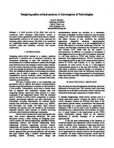
Let us assume that management nodes have static tables as shown in Table 1 whereas application nodes have dynamic tables as shown in Table 2 and furthermore that node 4 and node 8 fail at the times depicted in Figure 7. The nodes in the system detect that nodes 4 and 8 have failed because they did not transmit any signal on either channel in their time slot. The spare nodes and the backup manager nodes find out the successor of the failed nodes. In this example, node 15 is the substitute of node 4 and node 9 is the substitute of node 8. Nodes 15 and 9 begin by invalidating their host lifesign field and then request reconfiguration from its controller in order to take over the role of the failed nodes. Once the controller finishes the reconfiguration process nodes 15 and 9 have to activate the host lifesign field and their controllers will transit into ready state first and then into active state when they acquire their new slots. According to the TTP/C specification the reconfiguration process will take two TDMA rounds. Node 9 will be the next active management node and although its controller has to transit through the passive, configure, passive, ready and active states to complete the reconfiguration process, it can receive all the information the rest of nodes are sending while the reconfiguration process takes place. Therefore node 9 knows the state of each node and whether a failure occurs.
Node 1
What if a regular node and the active management node fail at the same time? The substitution is not a problem. Although the substitute of the failed management node has to transist through several states, it is always receiving messages and thus know the precise state of the system.
Detailed example The following example illustrates how the spare and backup management nodes take over the failed nodes when they fail even in the same TDMA round. The chosen system for the example is shown in the figure 6 where nodes through 1 to 7 are regular nodes.
0-7803-7108-9/01/$10.00 (C)2001 IEEE
Node 2
Node 5
What if the management node fails without assigning a successor? The remaining management nodes could try to get that role but there could be collisions. What if the node that has to take over a failed node is not able to reconfigure correctly? The active management node supervising the reconfiguration will ask a second backup node to take over the role of the failed node (if such backup node is available). For this situation, it will take 5 TDMA round to take over the role of the failed node.
FTU 2
FTU 1
Node 3
Node 7
Node 4
Node 12
Node 15
Node 13
Node 14
Node 8
Node 6
Node 9
FTU 3
Node 11
Node 10
FTU 4
Fig. 6. Application with 4 FTUs V. SUMMARY AND CONCLUSIONS A new fault management protocol that makes use of native fault tolerant features of TTP/C has been described. It can tolerate multiple nodes failures no matter how close in time and in minimum time. The main advantages of the protocol are that the management nodes need just one TDMA slot to perform its functions, the FTU’s share some backup nodes thus reducing the total number of backup nodes require to achieve a given level of dependability. The time it takes to detect a node failure and to reconfigure the system is minimum and it is fixed by the TTP/C protocol. This is so because before a node fails the nodes know what they have to do and they start to do it immediately after they detect a node failure without waiting for commands from the active management node. The protocol tolerates that several nodes, including the active management node, fail at the
1804
IECON'01: The 27th Annual Conference of the IEEE Industrial Electronics Society
same time and let the spare nodes reconfigure themselves in order to substitute the failed nodes. The protocol permits that a replicate node can belong to several FTUs at the same time with the only condition that it has to be able to run the role assigned to each FTU. This allows a higher level of dependability of the system keeping the same number of replicated nodes. Because all nodes of the system have to send a message at least once during a cluster cycle, the active management node knows the state (active, failed) of each node (regular application nodes, backup management nodes and spare nodes). Still another advantage is the high level of fault management provided. The disadvantages of the protocol involve the introduction of management nodes and associated TDMA slots. V. REFERENCES [1]
H. Kopetz, G. Grunsteidl, “TTP – A protocol for Fault-Tolerant Real-Time Systems”. IEEE Computer, pages 14-23, January 1994.
[2]
Specification of the TTP/C Protocol. Specification version 0.5 of 21-Jul-1999. TTTech Computertechnik AG
[3]
Kopetz, H., A. Krüger, R. Hexel, D. Millinger, R. Nossal, R. Pallierer, and C. Temple, Redundancy Management in the Time-Triggered Protocol, Technical. Report 4/1996, Technical University of Vienna, Vienna, Austria, 1996.
[4]
http://www.flexray-group.com Node 9 detects failure, requests reconfiguration Node 15 detects failure, requests reconfiguration
management slot regular application nodes Application message sent
1
2
3
4
5
6
7
8
A
B
C
D
E
F
G
M
15
spare slot
1
2
3
4
5
6
7
8
A
B
C
D
E
F
G
M
9
10
1
2
3
5
6
7
A
B
C
E
F
G
11
12
Node 4 fails TDMA round Node 8 fails Node 9 is reconfigured
Node 9 takes over node 8 Node 15 takes over node 4
Node 15 is reconfigured
1
2
3
5
6
7
A
B
C
E
F
G
13
14
1
2
3
15
5
6
7
9
1
2
3
15
5
6
7
9
A
B
C
D
E
F
G
M
A
B
C
D
E
F
G
M
Node 15 starts lifesign update Node 9 stars lifesign update
Fig. 7. Example of dynamic reconfiguration
0-7803-7108-9/01/$10.00 (C)2001 IEEE
1805
10