A Fault-Tolerant Dynamic Fetch Policy for SMT Processors in Multi-Bus Environments Bernhard Fechner Department of Computer Science FernUniversität in Hagen
[email protected] Abstract Modern microprocessors get more and more susceptible to transient faults, e.g. caused by high-energetic particles due to high integration, clock frequencies, temperature and decreasing voltage supplies. A newer method to speed up contemporary processors at small space increase is simultaneous multithreading (SMT). With the introduction of SMT, instruction fetch- and issue policies gained importance. SMT processors are able to simultaneously fetch and issue instructions from multiple instruction streams. In this work, we focus on how dynamic bus arbitration and scheduling of hardware threads within the processors front-end can help to dynamically adjust fault coverage and performance. The novelties which help to reach this goal are: A multi-busscheduling scheme which can be used to tolerate permanent bus faults and single event disturbances (SEDs). The second novelty can be used in conjunction with the first: A dynamic fetch scheduling algorithm for a simultaneous multithreaded processor, leading to the introduction of dynamic multithreading. Dynamically multithreaded processors are able to switch between different SMT fetch policies, thus enabling a graceful degradation of the processors front-end.
1. Introduction The growing performance requirements and application areas for modern microprocessors led to clock frequencies beyond multiple Gigahertz [9] and Nanometer minimum feature sizes. Now [6] a problem occurs at sea-level, which is known from aerospace: Heavy ions from deepspace, reacting in the earth’s atmosphere to high-energetic neutrons. If they collide with silicon, they will cause a partial or total failure of the concerned component. The consequence is an increased susceptibility for transient faults induced by Single Event Effects (SEEs). SEEs can be separated in temporal faults, causing a temporary malfunction or disturbance of digital information and permanent faults. Downtime costs by temporal faults caused by Single Event Upsets (SEUs)[5] have increased dramatically in the last years [10]. The rate of temporal errors in
combinatorial circuits will increase by approximately 105 from 1992 until 2011 [7]. For the next decade a total error rate of 104 FIT in combinatorial circuits is forecasted [8]. Thus, reliability is one of the factors to limit the trends from above, in the present and in the future - future microprocessors must be secured against SEUs. To reach this goal, this paper makes two main contributions: 1. The dynamic arbitration of hardware threads in a SMT front-end to access a multi-bus system which will be able to tolerate permanent bus faults as long as there is at least one bus available. 2. The dynamic reconfiguration between different SMT fetch policies, enabling the dynamical adjustment of performance/ fault coverage requirements to the intended application environment. Independent instruction streams are denoted as softwarethreads. A hardware-thread or thread is defined as all on-chip structures dedicated to hold data of a thread or have thread-specific control, assigned statically or dynamically. We assume a support for two hardware threads for the presented architecture. The context of a hardware thread is denoted as the current state of a hardware thread including registers, program counter and memory access registers. A context switch is a change of the hardware register context so that a different hardware thread will be able to fetch and execute. The rest of the paper is organized as follows: Related work is discussed in Section 2. Section 3 presents the fault model. Section 4 describes the front-end including bus arbitration and shows how permanent bus faults can be tolerated. In Section 5 we show how the proposed fetch algorithm helps to regulate performance/ reliability requirements. Section 6 summarizes the paper.
2. Related Work With simultaneous multithreading[2][3][4], fetch policies gained importance, since a SMT processor with enough front-end bandwidth is able to fetch different instructions from different threads simultaneously. For the sake of simplicity, this is not implemented in current SMT processors [16]. Here, only one thread will be allowed to ac-
cess the memory at a time. We share this opinion. Concurrency is achieved by either significantly increasing the bus clock frequency, the number of busses, multiple fetch units or an improved instruction cache. Except the case of multiple busses/ greater bus width, it is obvious that instructions cannot be fetched in parallel, but for the rest of the pipeline it will appear as concurrency. The fetch and issue policy significantly determines the speed of contemporary SMT microprocessors. If instructions are fetched by using the wrong policy, a slowdown will occur, since then the execution units can not be smoothly provided with instructions any more. Instruction fetchand issue policies for SMT processors were first analyzed by Tullsen et al. [1], thread-dependent issuing in [14]. Table 1 shows the most commonly used fetch policies. Table 1: Common SMT Fetch Policies Policy
Description
BRCOUNT
Number of branches of a thread.
LDCOUNT
Number of loads of a thread.
MEMCOUNT
Number of memory accesses of a thread. Number of instructions of a thread in fetch buffer, decode and rename stage, and instruction queue. Accumulated IPC of a thread
ICOUNT
ACCIPC STALLCOUNT RR
fetch policies leads to a higher IPC, this could indicate, that the more causes are considered, the higher the performance will get. However, the analysis in [13] did not regard the intended clock frequency and complexity of a fetch policy. A VLSI implementation will also have to regard the time to determine the thread which will be allowed to fetch and the space requirements. Inauspiciously, the forwarding of results over/ the counting of instructions in multiple stages is not a good idea in high integration, since this could easily take multiple cycles. Furthermore, it is unclear how and if the fetch policies from Table 1 regard multiple concurrent accesses to e.g. caches. Note, that the term dynamic multithreading (DMT) in [15] completely differs from the one used in this work. DMT will create threads dynamically at loops and procedure calls and does not involve the dynamic selection of multithreading strategies.
Number of total stall counts. Round-robin.
Round-robin (RR) cannot be seen as a real strategy because it does not consider any system conditions. Here, instructions are alternately fetched from threads. Because it is simple to implement, it is used in current processor realizations [16]. However, multimedia-based experiments [13] showed that RR seems to be the worst policy regarding the number of instructions per cycle (IPC) in comparison with a modified ICOUNT and BRCOUNT strategy. ICOUNT gives priority to threads with fewer number of instructions in the decode/ rename stage and the instruction queues (ISQ). As ICOUNT implementation, we suggest to use counters for the number of instructions of a thread in each stage. The counters are compared and the results (00=less, 01=equal, 10=greater) forwarded to the fetch stage. Here, we use a majority voter to determine the next thread. The BRCOUNT strategy gives higher priority to threads which are least likely to be on a wrong path, supposing speculative execution. The analysis in [13] suggested that combining strategies such as ICOUNT and IQPOSN is a better choice than to select a single strategy. Since RR has the worst IPC in comparison to other schemes and a combination of two
3. The Fault Model The Stuck-at Fault Model is the most common and general fault model for permanent logical faults. It assumes that a circuit fault manifests through the effect that one or more circuit nodes are stuck at 0 or 1 (SA01). Permanent faults are not the main cause for errors in semiconductors. The probability for temporal errors is 5 to 100 times higher [8]. Apart from radiation, they can be caused from power fluctuations, loosely coupled units, timing-faults, meta-stable states and environmental influences (temperature, humidity, and force). Single Event Upsets (SEUs) are transient faults in memory elements, e.g. caused by high-energetic particles hitting the die. SEUs are modeled by bit-flips (flip-to 0/ flip-to 1) of the corresponding latches or memory cells. Single Event Disturbances (SEDs) cause a temporal disturbance of digital information. We assume SEDs in the form of data faults on the busses and one fault at a time in one component since multiple bit faults are extremely seldom. A component is defined as a single pipeline stage or a single bus. Three basic error manifestations can be distinguished: 1. Latent: errors which are neither effective nor overwritten within a specified observation interval. 2. Overwritten: an error which is overwritten by a correct value before the wrong value was read. 3. Effective: an error is effective, if it manifests within the specified observation interval. The applied fault model is based on a generic processor fault model [12]. We will use this model, because it has been validated through applying it to various models of commercial processors. It is based on the simpler stuck-at and bit-flip models.
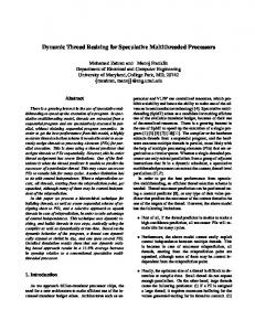
4. The Front-End Figure 1 shows a block diagram of the front-end including the instruction fetch and predecode stage. The bus controller is the main interface to the system bus. The fetching is done by the integrated fetch unit. The fetch unit determines the priority a thread can access the bus, furthermore the current mapping of a thread onto a bus. A novelty here is not to use a fixed fetch block width [22], since a fixed fetch block width is not able to tolerate any permanent bus faults. Figure 1 shows that the pipeline is asynchronous. The asynchronous design will help to prevent faults to become effective, since the latches/ registers will not be activated periodically. The probability of a transient fault in the clock tree is reduced due to less space occupation of the handshake logic and wiring. Less energy is consumed, because units will not be activated on each rising or falling clock edge. The problem of different signal arrival times can be solved e.g. by applying timing constraints during the routing of the concerned wires and/or by applying Muller-C elements [24]. Checksum storage and calculation Checksum Thread-ID
Instruction Fetch Instr. Stream Buffers
Thread_CHG
Data
P r e d e c o d e
M0
Fetch
ACK
M1
Thread_CHG
REQ
Addr.
Addr.
Data
Bus ctrl.
ThreadBus map
1 REQ
1
ACK Dependencies
enables the processor to start-up and run in environments with different performance/reliability requirements. The signals S, T, B and F in Table 2 are used for the mode selection (shown in Figure 1). Table 2: Mode signals B
F
S
T 0 1
0 1 0 1 0 1
Description Single-threaded. Dual-threaded. Cycle-by-cycle scheduling. Block-oriented scheduling. Disable redundant execution. Enable redundant execution. One address and data bus. Two address and data busses.
Naturally, only the transitions B=1→0; S={0|1}→{1|0}; T=0→1 should be possible during runtime if we only want to allow a transition from a less to a more dependable mode. On F=1, we assume equal code and data to be fetched from the RAMs. The RAMs are partitioned in a code and data area. We assume a maximum of two physically busses to access the RAMs. Both hardware threads will fetch and execute the same code and data from different RAMs. Over INTFAULT the processor will signal that is in failsafe mode. Failsafe mode is reached if an internal processor failure was detected so that the processor will not be able to safely continue its execution. Reaching failsafe mode will not power-off the processor. The failsafe signal is connected to each pipeline stage. Signaling from stage to stage is enabled by handshaking if one stage requests the other (REQ) or acknowledges (ACK) requests. Enabling failsafe mode will stop this signaling. Although simple, we show the failsafe-stop mechanism in Figure 2 for clarity.
History Voting
Branch prediction
Thread 1: Error History Thread 2: Error History
4/8
4/8
Thread Control File Thread 1 PC Thread 1 MEM1 Thread 2 PC Thread 1 MEM2 Thread 2 MEM1 Thread 2 MEM2
Thread 1 Credibility
Thread 2 Credibility
Bus 1 Credibility
Bus 2 Credibility
Failsafe Req Ack
Req Ack
Load Queues
Figure 2: Failsafe mode stopping pipeline operation Temporal Memory PC/MEM . Value . PC/MEM . Value
Store Queues
Figure 1: The Front-End After reset the front-end can be configured externally to run in different fault-tolerant (F) or non fault-tolerant modes. Fault-tolerant modes include the cycle-by-cycle or the latency-oriented scheduling of redundant threads. This
Additionally, clocked units will be deactivated since they are gated through the failsafe signal. External components can signal a fatal error by EXTFAULT . The processor will then immediately go into failsafe mode. A thread will be deactivated if it completely lost credibility. The credibility of a thread is determined by the history voting described in [11]. Additionally, we determine the credibility for a bus, since we can have a multi-bus configuration. If the credibility of a bus is zero, it will be deactivated, assuming a permanent fault. The bus configuration is stored
in a (stable) storage. It determines which thread accessed which bus the time the error was detected. Then we decrement the credibility of that bus. Note, that the credibility of a bus is independent from the thread accessing the bus. If the credibility is zero, the bus will be deactivated and all accesses be scheduled to the non-faulty bus. In the following sections, we describe the modes from Table 2 in detail. In all fault-tolerant modes involving (F=1), the checksum computation over the pipelined execution[19] and microcode timing[20] is enabled.
threads NUM_THREADS=1, so we do not do any context switches. 5.2. Cycle-by-Cycle (Redundant) Execution Cycle-by-cycle execution will be enabled on S=0, whereas threads are scheduled alternately to access the bus(ses). On F=1, the mode is comparable with a traditional virtual duplex system, working on a fine-grained time basis. In fact, the system appears to be lockstepped no system conditions are considered for the selection of threads in this mode.
5. Fetch Scheduling The fetch scheduling in a SMT processor front-end determines, which hardware thread can use the bus(es) next. It basically has to fulfill two different tasks: execute requests from the memory stage and fetch instructions. Furthermore, the priorization between memory accesses from the memory stage (reading or writing) and the fetch unit has to be considered. We distinguish three basic methods of fetch scheduling, which are known from former multithreaded systems [23]. • Cycle-by-cycle: threads are fetching alternately in each cycle. This is a special case of block-by-block scheduling with a fixed block size of 1. In our asynchronous case we have no dedicated clock, so we schedule threads alternately. • Block-by-block: a thread is fetching instructions for a fixed number of b cycles. This is closely related to the ICOUNT fetch policy. • Instruction-dependent: this is the classical controldriven multithreading. In this work, we assume the criterions for context switches to be encoded in the instruction stream. These are branches, loads and stores. This will preserve binary compatibility so that the ISA must not be changed. We will take a look at coherences in Subsection 5.5, showing a global overview of the fetch scheduling schemes which are described in the following sections and Figure 3.
5.1. Single-Threaded Configuration Single-threaded execution is enabled on the mode combination (T=0; B={0|1}; S=X; F=0). Here, one thread is active and no scheduling will occur. This mode is equivalent to the traditional uniprocessor execution. The only difference is that we can have two available busses. No fault-tolerance is activated in this mode although the combination (T=0;B={0|1};F=1;S={0|1}) is imaginable, since it would correspond to a virtual duplex system. The difference to cycle-by-cycle execution is that the number of
5.3. Redundant (Simultaneous) Multithreading Redundant multithreading is applied in many academic papers [17][18]. It basically consists of executing the same instructions twice on the same processor in different hardware threads and is enabled on T=1;B={0|1}; F=1;S=1. A delay buffer is used to forward results between threads. Results can be branch targets of conditional and unconditional branches and values. Threads are separated in a leading and a trailing (redundant) thread. It has been shown that a more sophisticated structure, the temporal memory can be used to forward results faster and how the branch target buffer (BTB) can be integrated [21]. A faulty leading thread could write a faulty value to main memory. The trailing thread could fetch this value, leading to the fact that no error can be detected. Therefore, the temporal memory is used to maintain consistency. Stores will be committed onto this memory by the leading thread. When a checkpoint is generated and the checksums produced by both threads are equal, this will lead to a writeback of the values in the temporal memory to main memory. Schemes like AR-SMT[17] use the ICOUNT policy to maintain an equal amount of instructions between the leading and the trailing thread. This amount of instructions is fixed. In this work, we will not use the ICOUNT policy to determine if the leading or the trailing thread can access the memory. Instead, we use the filling of the delay buffer/ temporal memory and instruction queues. We do not consider changing the role of a trailing into a leading thread and vice-versa because this will not bring any advantage in performance or faultcoverage. In contrary, the situation will be much more complicated, because both threads must have the same amount of write ports e.g. to the temporal memory.
N
BUSAVAIL1& BUSAVAIL2?
N
N
INTFAULT
N
BUSAVAIL2?
Y
Y
BUSAVAIL1?
Y
B=3
N
Thread1_CONF|| Thread2_CONF pt
Y
N a