Software Engineering represents a structured, disciplined approach to the .....
software development [14] is a modern approach to iterative development better.
A Feature-Oriented Software Engineering Approach Supporting Extension and Testing by Jeremy E. Denham A Thesis Submitted to the Faculty of the WORCESTER POLYTECHNIC INSTITUTE In partial fulfillment of the requirements for the Degree of Master of Science in Computer Science by
December 2009 APPROVED:
Professor George Heineman, Major Thesis Advisor
Professor Gary Pollice, Thesis Reader
Professor Mike Gennert, Head of Department
Abstract Software Engineering represents a structured, disciplined approach to the design and implementation of software systems. Adhering to such an approach enables greater planning for and management of systemic complexity. By augmenting the process to emphasize desired features that are to be present in the final software system, we can ensure that the final system will be modular, extensible, and testable with respect to individual features. Moreover, an existing system can be characterized according to its features and refactored in the same way. This thesis investigates feature-oriented augmentation to the standard software engineering approach. We employ logic-based feature models to characterize the features in the product family of an existing system. We use the characterized features to refactor a case study to reflect the approach using aspects. We demonstrate using the AspectJ Eclipse plugin how to publish different frameworks in a framework product line. Our results show that the refactoring efforts produce a modular, extensible, and testable system in which individual behavioral features selected from a product family of features can be added to or subtracted from the system with ease.
Acknowledgements I would like to thank Professor Heineman for his guidance and patience (lord knows I can try patience.) His ceaseless flow of ideas can be overwhelming at times, but ultimately it made for a very enriching experience. Well played, sir. I would also like to thank Professor Pollice reading this thesis and only halfheartedly telling me to leave his office on my umpteenth daily trip in to raid his candy bowl. Without his useful comments and tasty confections, this thesis would not have been possible. Thanks goes out to Professor Selkow for listening to me complain and guilting me into getting back to work. With an open door and an attentive ear, you helped get me past the many bumps in the road. To Mike Sao Pedro, whose shameless, constant, undying plugging of WPI got me into this wonderful, wonderful mess in the first place, thanks a million. Finally, I would like to thank the Computer Science department at large for providing an outstanding educational experience. Always engaging and demanding, rarely dull best sums up this department, and I could not be happier or more grateful for that.
i
Contents
1 Introduction 1.1
1.2
1.3
1
Software Engineering Processes . . . . . . . . . . . . . . . . . . . . .
2
1.1.1
Process-driven . . . . . . . . . . . . . . . . . . . . . . . . . . .
2
1.1.2
Paradigm-driven . . . . . . . . . . . . . . . . . . . . . . . . .
2
1.1.3
Product-line driven . . . . . . . . . . . . . . . . . . . . . . . .
3
Desired Software Qualities . . . . . . . . . . . . . . . . . . . . . . . .
3
1.2.1
Modular . . . . . . . . . . . . . . . . . . . . . . . . . . . . . .
3
1.2.2
Extensible . . . . . . . . . . . . . . . . . . . . . . . . . . . . .
4
1.2.3
Testable . . . . . . . . . . . . . . . . . . . . . . . . . . . . . .
4
1.2.4
Process . . . . . . . . . . . . . . . . . . . . . . . . . . . . . .
4
Case Study . . . . . . . . . . . . . . . . . . . . . . . . . . . . . . . .
5
2 Background
6
2.1
Feature Modeling . . . . . . . . . . . . . . . . . . . . . . . . . . . . .
7
2.2
Feature Refinement / AHEAD . . . . . . . . . . . . . . . . . . . . . .
8
3 Technologies 3.1
10
Eclipse IDE . . . . . . . . . . . . . . . . . . . . . . . . . . . . . . . . 10 3.1.1
History . . . . . . . . . . . . . . . . . . . . . . . . . . . . . . . 10
3.1.2
Architecture . . . . . . . . . . . . . . . . . . . . . . . . . . . . 11 ii
3.2
AspectJ . . . . . . . . . . . . . . . . . . . . . . . . . . . . . . . . . . 11
4 Case Study
13
4.1
Introduction . . . . . . . . . . . . . . . . . . . . . . . . . . . . . . . . 13
4.2
Frameworks . . . . . . . . . . . . . . . . . . . . . . . . . . . . . . . . 15
4.3
Meta Infrastructure Framework . . . . . . . . . . . . . . . . . . . . . 16
4.4
4.5
4.6
4.7
4.3.1
Features . . . . . . . . . . . . . . . . . . . . . . . . . . . . . . 17
4.3.2
Non-hierarchical Feature Dependencies . . . . . . . . . . . . . 18
Refactoring . . . . . . . . . . . . . . . . . . . . . . . . . . . . . . . . 19 4.4.1
Phase I: Native Code Migration . . . . . . . . . . . . . . . . . 19
4.4.2
Phase II: “Aspectualizing” References . . . . . . . . . . . . . . 19
Example: Undo / Redo . . . . . . . . . . . . . . . . . . . . . . . . . . 20 4.5.1
Undo . . . . . . . . . . . . . . . . . . . . . . . . . . . . . . . . 20
4.5.2
Redo . . . . . . . . . . . . . . . . . . . . . . . . . . . . . . . . 24
Challenges to Refactoring . . . . . . . . . . . . . . . . . . . . . . . . 25 4.6.1
Reference Catching . . . . . . . . . . . . . . . . . . . . . . . . 25
4.6.2
Anchor Points and Feature Ordering . . . . . . . . . . . . . . 25
4.6.3
Pointcut Definition . . . . . . . . . . . . . . . . . . . . . . . . 28
Why Not Native? . . . . . . . . . . . . . . . . . . . . . . . . . . . . . 29
5 Experimentation
31
5.1
Framework Feature Selection . . . . . . . . . . . . . . . . . . . . . . . 31
5.2
Why Not Native Revisited . . . . . . . . . . . . . . . . . . . . . . . . 33
5.3
Built-in Benefits . . . . . . . . . . . . . . . . . . . . . . . . . . . . . . 33
5.4
Framework Product Line . . . . . . . . . . . . . . . . . . . . . . . . . 34 5.4.1
CPM eta & BM eta . . . . . . . . . . . . . . . . . . . . . . . . . . 34
5.4.2
Base + Individual Features . . . . . . . . . . . . . . . . . . . 35
iii
5.4.3
CPM eta \ {undo, redo, logger} . . . . . . . . . . . . . . . . . . . 35
5.4.4
BM eta ∪ {clipboarddelete} & BM eta ∪ {clipboarddelete, clipboard, paste} . . . . . . . . . . . 35
5.4.5
Random Subset . . . . . . . . . . . . . . . . . . . . . . . . . . 36
6 Results 6.1
37
Modularity 6.1.1
. . . . . . . . . . . . . . . . . . . . . . . . . . . . . . . . 37
Undo / Redo: The Rest of the Story . . . . . . . . . . . . . . 38
6.2
Extensibility . . . . . . . . . . . . . . . . . . . . . . . . . . . . . . . . 39
6.3
Testability . . . . . . . . . . . . . . . . . . . . . . . . . . . . . . . . . 42 6.3.1
Traditional Means . . . . . . . . . . . . . . . . . . . . . . . . 43
6.3.2
Aspect-specific Means . . . . . . . . . . . . . . . . . . . . . . 43
7 Conclusions 7.1
48
Future Work . . . . . . . . . . . . . . . . . . . . . . . . . . . . . . . . 49
A AHEAD Tools
53
B Integration Test for revert
54
iv
List of Figures 2.1
A sample feature model . . . . . . . . . . . . . . . . . . . . . . . . .
7
2.2
Functions as collectives of constants . . . . . . . . . . . . . . . . . . .
9
2.3
Composition of functions . . . . . . . . . . . . . . . . . . . . . . . . .
9
3.1
Sample aspect . . . . . . . . . . . . . . . . . . . . . . . . . . . . . . . 12
4.1
Sample MS Paint window . . . . . . . . . . . . . . . . . . . . . . . . 14
4.2
Sample MS Notepad window . . . . . . . . . . . . . . . . . . . . . . . 15
4.3
Feature model for Meta . . . . . . . . . . . . . . . . . . . . . . . . . . 17
4.4
Sample application derived from Meta . . . . . . . . . . . . . . . . . 18
4.5
Non-hierarchical feature dependencies in PM eta . . . . . . . . . . . . . 19
4.6
Feature.aj file for logger feature . . . . . . . . . . . . . . . . . . . . . 20
4.7
Undo directory after class file relocation . . . . . . . . . . . . . . . . 20
4.8
Interface-dependent refactored code . . . . . . . . . . . . . . . . . . . 21
4.9
Pointcut to catch an unhandled ActionEvent with respect to undo . 23
4.10 Pointcut to add undo-related menu items to the Edit Menu . . . . . . 24 4.11 Pointcut to add redo consideration into undo() . . . . . . . . . . . . 24 4.12 Sample File menu . . . . . . . . . . . . . . . . . . . . . . . . . . . . . 26 4.13 Two anchor points for the Print menu item . . . . . . . . . . . . . . . 27 4.14 Sample File menu with improper feature ordering . . . . . . . . . . . 28
v
4.15 Sample FeatureOrdering aspect . . . . . . . . . . . . . . . . . . . . . 28 4.16 Excerpt from paste.Feature.aj . . . . . . . . . . . . . . . . . . . . 30 5.1
Sample ajproperties file: CPM eta \ {undo, logger} . . . . . . . . . . . . 32
6.1
Import problems in undo.Feature.aj in the absence of all other features . . . . . . . . . . . . . . . . . . . . . . . . . . . . . . . . . . . . 38
6.2
Sample feature directory with native Java classes . . . . . . . . . . . 43
6.3
Sample unit test for PrintingManager.java . . . . . . . . . . . . . . 43
6.4
Graphical crosscutting annotations in Eclipse . . . . . . . . . . . . . 45
6.5
AJDT Cross-references view . . . . . . . . . . . . . . . . . . . . . . . 45
6.6
AJDT Crosscutting Comparison view . . . . . . . . . . . . . . . . . . 46
7.1
Approaches to framework refinement through feature selection . . . . 50
vi
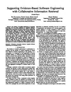
Chapter 1 Introduction The discipline of Software Engineering exists to provide a structured approach to design and implement software systems. By following a software engineering practice or methodology, software designers are better able to plan for and manage complexity during the implementation phase, which can in turn simplify the development of test cases for both the overarching system and its component subsystems. Our research is focused on identifying ways to alter a software process to emphasize desired features that are to be present in the final software system. By identifying these features early in the process, we can perform additional steps during the software analysis phase to ensure three specific qualities of the resulting system: 1. The majority of the identified features are cleanly encapsulated in modular units that can be assembled to form desired applications with those features. 2. Individual features can be extended, and indeed, these extensions do not restrict further extensibility. 3. Individual features and extensions can be tested independently in isolation.
1
With a refactoring exercise performed on a case study, we show that aspects can be used to provide a clean, modular abstraction for systemic features that lend themselves nicely to extension and testing.
1.1
Software Engineering Processes
There are numerous software engineering methodologies, each one designed to address a specific limitation of how software is developed and maintained. These methodologies are not, however, mutually exclusive; hybrid approaches may be developed.
1.1.1
Process-driven
The Spiral Model [13] is designed for large, complex systems by ensuring strong customer feedback during relatively short periods of iterative development. Agile software development [14] is a modern approach to iterative development better suited to smaller projects, yet it too promotes a tight development cycle with strong customer focus.
1.1.2
Paradigm-driven
Often the use of a specific paradigm enables a change to be made to the software process. The popularity of object-oriented languages enabled software engineers to develop different processes that were able to take advantage of the capabilities of these languages. The hallmark of an object-oriented software development process is the focus on reducing the gap between the application domain and the solution domain. Typically, software engineering specifications are captured by interviewing the client requesting the software. However the final solution is to be coded using 2
technical concepts as coded by the software engineer. Using an object-oriented process, the focus is on transforming application domain concepts into classes that are then ultimately realized in the solution domain. In this way, the language used to develop artifacts in the solution domain. A recent trend in the Aspect-oriented programming community is to focus on Early Aspects [11]. The idea is to develop a methodology that can identify aspects during the requirements gathering phase. If successful, the process can more clearly identify artifacts that will be necessary during the implementation phase.
1.1.3
Product-line driven
When the requirement is to produce a family of similar products, the software engineering process can be altered to attempt to maximize reuse of the developed artifacts used to compose together the various members of the product line family [12]. A critical step is identifying features that belong to the family and which belong to different members of the family as appropriate. Various technologies can then be employed to rapidly assemble applications that embody various features.
1.2
Desired Software Qualities
The focus of a software engineering process, naturally, is on the means by which software is developed. However, there are various qualities desired of the software artifacts produced during the process.
1.2.1
Modular
When solving complex problems, one must decompose the problem into smaller problems. When applying modularity to software design, the goal is to design clearly 3
defined units that hide non-essential details (such as implementation details) while presenting a clean interface. Programming languages provide rudimentary units, such as functions, that enable the stepwise refinement [10] of a task into smaller units. The object-oriented paradigm supports the clean encapsulation of concepts into classes that hide their implementation. AOP produces modular aspects that can be woven into a base system to produce the desired behavior.
1.2.2
Extensible
Software systems continually evolve, as new requirements are discovered or new opportunities arise. Obsolete software applications often become obsolete because their internal structure makes it too costly to extend to include additional capabilities. It is important to state that modularity by itself does not always guarantee extensibility.
1.2.3
Testable
While testing can only determine when defects exist, it is the most commonly used mechanism to ensure quality of code. If one is unable to independently test smaller units of a larger system, there is a greater risk in defects remaining. Modularity should enable independent testing, though poor planning and construction might prevent this from happening. Extensible systems are (almost by definition) difficult to test because of the numerous ways by which they can be extended.
1.2.4
Process
One final concept that we wish to investigate regards the process by which features are selected for inclusion in a software system. In some cases, the code developer
4
builds and releases a set of applications with differing feature sets (from which a consumer picks one). A more powerful alternative is to delay system assembly until the consumer has selected the desired features, at which point the system can be assembled.
1.3
Case Study
Through the lens of a case study, we demonstrate how to capture features and map their corresponding code fragments to them. The case study focuses on the Meta Infrastructure Framework developed by Professor Heineman. We adapt the project using the proposed feature-oriented model, implement the project using existing modular technologies, and develop a “framework product line” based on the notions of feature extensibility. Developing a framework is different from developing an application since the framework is not executable - only applications derived using the framework are executable [9]. For the purpose of the case study, we utilize an Aspect-oriented framework (AspectJ) to refactor an existing code base in order to help modularize the system with regards to its behavioral facets. We then show how individual features may be extended and tested. Finally, we show how one would realize an individual framework by adding or subtracting features from a given framework.
5
Chapter 2 Background There has been a great deal of research into the realm of feature models; for our purposes, we will use the model developed by Czarnecki et al [1]. Here are some key terms: · A feature of a software system is an incremental, possibly optional, unit of functionality [3][4]. · A feature model is a notation and an approach for modeling commonality and variability in product families (a formalism for the description of features and feature refinements) [1]. · A feature refinement is a module that encapsulates individual features [2]. Prior to its development as a software engineering paradigm, feature-oriented design was developed to express features and their interactions in complex telecommunication systems [3], [4]. Telecommunications companies began to structure the process of rapidly adding new features such that they were confident that the functionality of existing features could be maintained. The primary analysis goal was to identify when two features interacted, and to ensure that both features continued to function 6
Figure 2.1: A sample feature model properly. Because it is highly unlikely for features to remain completely independent, we need to augment our feature model with semantic knowledge of the interactions that occur within it. Cameron et al. proposed a dual-layered categorization technique which considered both the nature of interactions and the cause of interaction [3]. We will perform our work within this taxonomy.
2.1
Feature Modeling
According to Czarnecki, feature models, in their basic form, contain mandatory / optional features, feature groups, and implies and excludes relationships [1]. A feature model is a tree of features, whose root encapsulates the base feature, the minimum unit of functionality required for the existence of the system. Other nodes in the tree represent either solitary features, which can be optional or mandatory, or grouped features, which can be either exclusive-or groups or or-groups. Feature models constructed in this way allow software designers great flexibility in analysis and configuration of features within a system in a number of ways. First, they provide concrete formalisms for reasoning about features. Second, the formalisms themselves can logically be verified against specified behavioral requirements. Finally, they represent a standard medium of communication that can be
7
readily understood and reproduced [1].
2.2
Feature Refinement / AHEAD
Step-wise refinement of programs is a general paradigm devised by Wirth that considers the development of complex programs by incrementally adding details to relatively simpler programs [5]. A natural extension to this paradigm is feature refinement as earlier defined. Batory et al. point out that unlike traditional software packaging methodologies that encapsulate complete classes, feature refinements are additionally able to encapsulate fragments of multiple classes (as one might expect, given the nature of features) [2]. Prior to the work by Batory, feature refinements were focused on the realm of refinement of individual programs. In fact, Batory’s own GenVoca model [6] adhered to this principle. As Batory points out, however, most modern software systems span multiple groups of sophisticatedly collaborating programs [2]. To scale step-wise feature refinement to reflect such changes in the structure of modern systems, Batory presented the Algebraic Hierarchical Equations for Application Design (AHEAD) model. In the AHEAD model, base artifacts are constants and artifact refinements are functions. Any artifact resulting from a chain of refinements is modeled as a series of function applications to a constant. Composition is achieved by pair-wise function composition with respect to the constants that comprise the function. Furthermore, composition is polymorphic, which allows for generality across artifact types. Figure 2.2 shows a sample of constants and functions, and Figure 2.3 gives an example of functional composition [2]. For more details on the AHEAD Tool Suite, see Appendix A.
8
Figure 2.2: Functions as collectives of constants
Figure 2.3: Composition of functions
9
Chapter 3 Technologies We briefly review the technologies to be used for this case study.
3.1
Eclipse IDE
The software development for this thesis was done in the Eclipse Integrated Development Environment (IDE).
3.1.1
History
Eclipse is an open source development platform comprised of extensible frameworks, tools and runtimes for building, deploying and managing software across the lifecycle [16]. The Eclipse Project was created in 2001 by IBM and is supported by a consortium of software vendors. In 2004, the consortium, which comprised the Eclipse Board of Stewards, reorganized the Eclipse Project into the Eclipse Foundation, a not-for-profit corporation designed to steward the Eclipse community. As part of their mission statement, the Eclipse Foundation aims to provide four distinct services to the Eclipse community:
10
1. IT Infrastructure 2. Intellectual Property Management 3. Development Process 4. Ecosystem Development
3.1.2
Architecture
Platform The Eclipse platform defines the common programming-language-neutral infrastructure [17]. Java Development Tools The Java development tools add a full-featured Java IDE to Eclipse [17]. Plug-In Development Environment (PDE) The PDE extends the Java Development Tools with support for developing plug-ins [17].
3.2
AspectJ
Aspect-Oriented Programming (AOP) is a programming paradigm where code is dynamically modified during compilation according to programmatic constructs known as aspects that consist of pre-declared code changes [7]. The process by which such changes are made is called weaving. AspectJ is an extension of Java whose goal is to modularize aspects. AspectJ supports two types of programmatic transformations, static and dynamic. Static transformations are exemplified by introductions, which 11
aspect FaultHandler { private boolean Server.disabled = false; private void reportFault() { System.out.println(‘‘Failure! Please fix it.’’); } public static void fixServer(Server s) { s.disabled = false; { pointcut services(Server s): target(s) && call(public * *(..)); before(Server s): services(s) { if(s.disabled) throw new DisabledExecption(); { after(Server s) throwing (FaultException e): services(s) { s.disabled = true; reportFault(); } } Figure 3.1: Sample aspect statically introduce additional information to existing classes and interfaces. Dynamic transformations, on the other hand, run additional code when certain events occur during program execution. Such events are called join points, and join points are selected according to criteria defined in predicates known as pointcuts. Advice is code executed before, after, or around each join point matched by a pointcut. Figure 3.1 shows an example aspect, which is the basic unit of modularity for programmatic concerns that cut across many natural modular units [18].
12
Chapter 4 Case Study 4.1
Introduction
During the course of application development involving Graphical User Interfaces (GUIs), common well-documented functionalities become readily apparent. Such similarities among GUI applications afford shallower learning curves for their users. Moreover, these common functionalities lend themselves nicely to GUI product lines (concrete applications within the same product families.) Consider, for example, Figure 4.1 [9]. Figure 4.1 represents a screen-capture of a sample Microsoft Paint window. The window itself is an application shell consisting of a number of menus and a panel into which the primary program functionality is displayed and with which the program may be interacted. The menus themselves offer numerous interactive commands: the File menu offers commands to create a new document, open an existing document, save an existing document, etc. The Edit menu allows a user to undo and redo commands, as well as cut, copy, and paste domain-specific elements from a document. On the far right of the menu bar, there is a Help menu, in which one
13
Figure 4.1: Sample MS Paint window
14
Figure 4.2: Sample MS Notepad window would expect to locate information related to the use of the program as well as the program itself. While there are three domain-specific menus in the middle of the menu bar, the bulk of the other menu content is generic and can be reused across applications. Next, let us consider Figure 4.2 [9]. Figure 4.2 represents a screen-capture of a sample Microsoft Notepad window. As is the case with the Paint window, we note the existence of the File, Edit, and Help menus. Of course, there is once again domain-specific content, but the generic common functionalities between the two applications are clear components of a product family. For the purpose of this thesis, we are concerned with the integration of these “generic” feature components into a framework.
4.2
Frameworks
A framework is a programmatic mechanism that allows for the development of applications. A framework can be thought of as an application skeleton; for an applica15
tion to utilize a framework, it must realize (implement) or override (replace the logic within) the necessary method calls provided by the framework in a manner befitting its specific domain. As one might expect, whereas an application is executable, a framework is not. Only applications derived from the framework are executable [9]. However, even though a framework is not directly executable, this does not preclude frameworks from the realm of product lines. Instead, we are required to think about framework product lines in a slightly different way. A published framework F with respect to a product family P is a framework such that the behavior published for realization or overriding by an application derived from F is entirely encapsulated by features described by P (i.e. for any feature f , f ∈ F ⇒ f ∈ P .) A Base Framework BP with respect to a product family P is a framework encapsulating the minimal set of features necessary for an application to function in a useful way. A Complete Framework CP with respect to a product family P is a framework such that ∀f ∈ P , f ∈ CP . A framework product line FP with respect to a product family P is a set of unique published frameworks {Fi } such that ∀F ∈ {Fi }, F is a published framework with respect to P and BP ⊆ F ⊆ CP .
4.3
Meta Infrastructure Framework
The Meta Infrastructure Framework (Meta) was developed by Professor George Heineman using standard object-oriented design principles [9]. It was implemented in native Java. Our case study was focused on refactoring the framework in a manner compliant with our proposed feature-aware techniques.
16
Figure 4.3: Feature model for Meta
4.3.1
Features
To proceed with the refactoring of Meta, we first established the product family with which Meta would be associated. This was done through careful behavioral inspection of a realized application derived from Meta and the Meta code base itself. Figure 4.3 demonstrates the Czarnecki feature model derived for Meta. From this feature tree, we can ascertain the product family PM eta available to any potential framework product line involving the features present in Meta. Each node in the feature tree (except the root) represents a feature in PM eta . Any child node of the root attached with a darkened circle is required by the base system and is thus present in BPM eta . A child attached to a node by a white circle is considered
17
Figure 4.4: Sample application derived from Meta optional with respect to the parent feature (or in the case of the root, the base system.) Figure 4.4 shows a sample application derived from a framework in the Meta product family.
4.3.2
Non-hierarchical Feature Dependencies
The Czarnecki Feature Tree model establishes a general purpose feature hierarchy for a product family. However, it can not sufficiently capture all feature dependencies. In certain cases, non-hierarchical dependencies exist between features that otherwise appear unrelated, whether through virtue of existing in different feature subtrees or through a general lack of expressiveness of the Czarnecki model. Figure 4.5 outlines the non-hierarchical feature dependencies in PM eta .
18
clipboard ∈ F ⇔ paste ∈ F clipboard ∈ F ⇒ cut ∈ F clipboard ∈ F ⇒ copy ∈ F recent models ∈ F ⇒ pref erences ∈ F redo ∈ F ⇒ undo ∈ F page setup ∈ F ⇒ print ∈ F Figure 4.5: Non-hierarchical feature dependencies in PM eta
4.4
Refactoring
The refactoring effort required a good organizational mechanism in order to allow construction of framework product lines within the boundaries of AspectJ. Our strategy was to incrementally organize all native code and aspects related to a given feature in the product family in a package within a directory in the project called aspects. For each feature, the refactoring effort consisted of two phases.
4.4.1
Phase I: Native Code Migration
The first phase consisted of simple relocation of independent .java files related to the feature from their locations in the src folder to the corresponding package in the aspects directory. During the product family identification phase we were forced to examine the code base in depth to filter individual features, so the code location for this phase was not especially difficult. Additionally, because Eclipse is capable of automatically updating all references within a code base to files and their respective code, a potential point of complication was avoided entirely.
4.4.2
Phase II: “Aspectualizing” References
Once the relevant classes were relocated to the proper package, the next task was to “aspectualize” all references to them in the original code base. What is meant by
19
public privileged aspect Feature { after() : execution(boolean Startup.initialize(..)) { CommandManager cm = CommandManager.instance(); cm.registerListener(new LogManager()); } } Figure 4.6: Feature.aj file for logger feature
Figure 4.7: Undo directory after class file relocation this is the references in question needed to be woven in by means of AspectJ advice. In order to minimize complexity and maintain modular constancy, all advice for a given feature is consolidated in a single aspect file within the feature package called Feature.aj. Figure 4.6 shows a simple Feature.aj file from the Meta product family.
4.5 4.5.1
Example: Undo / Redo Undo
One of the more complex and challenging features present in PM eta is undo. To assess the overall feasibility of the refactoring exercise, we began our efforts by attempting to “aspectualize” the undo feature. Once we had relocated all the relevant class files to the proper directory (see Figure 4.7), we were ready to refactor the references. As became a common theme throughout the exercise, we first migrated the
20
public void CommandManager.processUndo (ReversibleCommand c) { synchronized (listeners) { for (int i = 0; i < listeners.size(); i++) { listeners.get(i).undone(c); } } } Figure 4.8: Interface-dependent refactored code reference to the “Undo” command from the Internationalization class to com.metaframing.undo.Feature.aj (for the remainder of the section to be referred to simply as Feature.aj). For the purposes of our system, we also grouped together the “Add Checkpoint” and “Undo upto Last Checkpoint” commands under the behavioral heading of undo, so those commands also needed to be removed from Internationalization. We next detected a non-hierarchical dependency when we tried to refactor the processUndo() method from the CommandManager class. Though we were able to do this successfully, this led us to examine the undone() method invoked within (see Figure 4.8.) This method was present in the ICommandHistory interface. From there we decided to try to remove undone() from ICommandHistory. We were, however, unsuccessful in this endeavor; AspectJ, as it turns out, (wisely1 ) disallows an aspect from weaving code into an interface. As a result, we grouped ICommandHistory with the logger feature and determined that the dependency logger ∈ F ⇒ undo ∈ F was present in PM eta . Meta provides the notion of a “command” as part of any framework. When Meta was originally designed, however, its Command class was designed with undo in mind. Worse yet, it was designed with the notion that only some commands 1
Interfaces are designed with consistency in mind. If we could dynamically modify an interface as we deemed fit, it would completely defeat the purpose!
21
could be undone. This behavior was reflected with the ReversibleCommand and NonReversibleCommand subclasses, and to be fair it is a good design. However, in a system where undo simply does not exist, there should be no such distinction. Because Command is an abstract class, we were able to remove the references to undo within the class and place them in Feature.aj. Fixing the problem of reversible and non-reversible commands was a bit more challenging, though. AspectJ does allow its aspects to “re-parent” classes with the syntax declare parents :Type1 extends Type2. As one might expect, this declaration sets the parent class of Type1 to be Type2. Thus, to mitigate the reversibility of commands problem, we had to go through each individual command class present in Meta, change the parent class to Command, then add a corresponding declare parents statement to Feature.aj based upon whether or not the command was to be reversible or non-reversible in the presence of undo. Also, in the case of reversible commands, the specific implementations of the undo() method needed to be added to Feature.aj. The process was a bit tedious to bootstrap, but if other commands were to be added, all that would be needed would be to add the relevant re-parenting directive and the specific undo() implementation as previously mentioned. The next step was to modify the relevant menu controller to handle undorelated commands, specifically the controller for the Edit Menu. This was a simple matter of weaving in the proper conditionals for the event handler within the EditMenuController class. Figure 4.9 demonstrates the pointcut that facilitates catching an unhandled ActionEvent within EditMenuController.actionPerformed(). This pointcut proved quite reusable, modulo fine tuning for specific controller classes. After modifying the EditMenuController class, we found ourselves tasked with modifying the parent class for internal frames to be used within a Meta-derived
22
after(EditMenuController emc, ActionEvent e) returning : this(emc) && execution(void EditMenuController.actionPerformed(ActionEvent)) && args(e) Figure 4.9: Pointcut to catch an unhandled ActionEvent with respect to undo application, namely the MetaInternalFrame class. Because each internal frame should be responsible for its own undo stack, the original Meta framework had the MetaInternalFrame class implement an interface for an undo controller called IUndoController.
As with the systemic commands, we thus had to reparent
MetaInternalFrame with an appropriate declare parents directive. To manage the undo stack, an UndoManager was also envisioned for Meta. This was included as an attribute within MetaInternalFrame, so we factored out the attribute and its initialization, along with all undo-related method calls. The final task associated with the refactoring of undo was removing the relevant references from the entry point for a Meta-derived application, the MetaApplication class. This involved moving the relevant menu item attributes from the class as well as the accessors and constructors. There was a slightly more subtle problem, though, which came about when dealing with the addition of the items themselves to the Edit Menu. This topic is addressed more generally and more in depth in Section 4.6.2, but essentially, we needed to guarantee that the Undo menu item would show up in the proper order within the Edit Menu. Figure 4.10 demonstrates the pointcut / advice directive used to facilitate this weaving. Because all of the features within the Edit Menu are optional (though for simplicity, we classify the Edit Menu itself as part of BM eta ), the call to setText() is the only acceptable join point for weaving. If, however, this call signature was repeated within the code for MetaApplication.getEditMenu(), this would be unacceptable as the code would be woven at multiple join points. 23
after(MetaApplication appl) : call(void setText(..)) withincode(JMenu MetaApplication.getEditMenu()) && !within(Feature) && this(appl)
&&
Figure 4.10: Pointcut to add undo-related menu items to the Edit Menu void around(UndoManager um) : this(um) && execution(void UndoManager.undo(..)) && !within(Feature) Figure 4.11: Pointcut to add redo consideration into undo()
4.5.2
Redo
Because undo and redo are so closely related, it almost doesn’t make sense to talk about them independently. However, it is not impossible to imagine a developer wanting to implement undo but not redo (time constraints or systemic simplicity, for example, may motivate such a decision.) To that end, we decided to decouple undo and redo and place them in their own separate feature directories. Most of the refactoring process for redo was identical to that of undo, and for the sake of brevity, we will not reiterate the common / similar elements. However, redo was interesting in and of its own right because it represented an extension of undo. To make redo work, we had to modify the UndoManager to reflect the necessary behavior. This first involved adding an additional command stack onto which reversible commands could be pushed after being “undone.” After adding said stack attribute to UndoManager and its initialization, we added support for the redo() method to the class. The final and trickiest step was to modify the undo() and undoToLastCheckPoint() method calls to factor in the newly-added redo command stack. Getting this to work properly involved replacing the existing execution with an around aspect advice directive and replacing it with the modified version of the execution. Figure 4.11 demonstrates the pointcut / advice directive used to insert redo consideration into the undo() method call.
24
4.6
Challenges to Refactoring
The idea of refactoring Meta is in principle not especially complicated. In practice, however, there are a number of potential complications that can arise.
4.6.1
Reference Catching
While refactoring is aimed at reducing feature-related complexity within Meta, the fact remains that some features are spread across multiple files and consist of multiple base classes, each with a potentially great number of methods. As such, simply searching the original code base for each instance of each method of each class is simply not always feasible. Finding all references to a particular class or method associated with a given feature, however, can potentially be very difficult. Worse yet, the very aspect of Eclipse that enables reference relocation can hinder aspectualizing efforts: if, for example, a reference is left in the original code base and all other references are properly aspectualized, the system will function exactly as intended! This problem can be corrected, however, by disabling the refactored feature.
4.6.2
Anchor Points and Feature Ordering
Consider the sample File menu pictured in Figure 4.12. In order to construct such a menu, we need to add each of the menu items to the menu. This imposes a natural ordering for each of the menu items. Let us consider the Revert menu item in the sample File menu. We note that there are two separator bars surrounding the Revert menu item. Like any other element of the menu item, these separator bars must be explicitly added to the menu bar. We should naturally assume that the separator bar above the Revert item is associated with the Revert item (it exists to separate the Revert item from another logical grouping of menu items.) But what
25
Figure 4.12: Sample File menu about the separator bar below the Revert item? One way to view that separator bar is as a dividing line between the Revert item and the Print-associated menu items. However, suppose the Print-associated features were all absent from the system. If that had been the case, then the lower separator bar would be entirely unnecessary. Similarly, suppose the Revert feature was absent from the system. Again, this would render the lower separator bar superfluous. What if we simply associate the lower separator bar with the Print menu item? Suppose the Print feature (and because of the aforementioned non-hierarchical dependencies, Page Setup as well) were removed from the system. We would be left with the Print Preview menu item, but no separator bar! This scenario highlights the precarious issue of anchor points. An anchor point is a point of execution within a system to which code that must execute in a particular order may “anchor” itself. More precisely, an anchor point is a pairing of a join point and advice such that the order in which the advice is applied follows a strict temporal execution sequence relative to the code in the join point. Unfortunately, this is not even the most dangerous issue involving anchor points.
26
Figure 4.13: Two anchor points for the Print menu item Consider again the Revert and Print menu items (we will for the moment disregard the separator bars.) It is safe to anchor the Revert menu item to the call that adds the Save As menu item to the File menu since the save as feature is present in BPM eta , but what about the Print menu item? We do not want to anchor Print to Revert, as both are optional features. It would thus seem that both features require the same anchor join point to impose their ordering. Or perhaps we could instead anchor both items to the Exit menu item call. If we strip out all optional features, we find that these actions should hypothetically be equivalent. Figure 4.13 demonstrates these two candidate anchor points for the Print menu item. In and of itself, AspectJ does not make any guarantees regarding the ordering of aspects. Figure 4.14 demonstrates how this could all go wrong. However, this problem can be solved by utilizing AspectJ advice precedence directives. In AspectJ [18], an aspect may declare a precedence relationship between concrete aspects by utilizing directives of the form: declare precedence :
TypePatternList ;
So if, for example, we wanted to ensure that the advice defined in the revert.Fea27
Figure 4.14: Sample File menu with improper feature ordering public privileged aspect FeatureOrdering { declare precedence: com.metaframing.printing.Feature, com.metaframing.revert.Feature } Figure 4.15: Sample FeatureOrdering aspect ture.aj file was applied before the advice defined in the printing.Feature.aj file, we would create an aspect like the one in Figure 4.15.
4.6.3
Pointcut Definition
Perhaps the most frustrating roadblock involved in refactoring Meta came in the form of simply constructing pointcuts. There is most assuredly a learning curve involved with pointcut construction; indeed, it was not uncommon for us to construct a pointcut that for all intents and purposes seemed correct but would weave in advice more places than expected or not at all. Once the learning curve was circumvented, though, another problem presented itself. Let us revisit the problem of the two separator bars. Why could we not have just statically added both separator bars and used them as anchor points? After all, the 28
around advice directive would allow us to swallow up one or both of the separator bars by designing a pointcut to select the invocation of their additions to the File menu. The answer is AspectJ pointcuts just are not that smart, unfortunately. There is no clean way to say “select call to add the separator bar after the Save As menu item is added but not the second one.” Generally speaking, the solution to this problem came in the form of selecting unique anchor points, by which is meant anchor points constructed such that the involved pointcut will select only one join point. As an example, consider the anchor point example in Figure 4.13. There are two potential candidate join points that would yield the desired results; what is not shown in the figure is the rest of the getFileMenu() method. There is an additional call to getSaveAsMenuItem() to add an action listener to the Save As menu item, but there is no such call for the Exit menu item. Thus, getSaveAsMenuItem() does not constitute a suitable join point for our purposes, but by virtue of its contextual uniqueness, the call to getExitMenuItem() is suitable.
4.7
Why Not Native?
It is all well and good for us to argue that an aspectualized refactoring of Meta is a worthwhile approach. However, one might ask, “why not just refactor the code according to feature-aware design tenets in native Java?” To illustrate precisely why native Java is not an attractive option, let us consider a small snippet from paste.Feature.aj as illustrated in Figure 4.16. We notice that the aspect weaves code into four different classes, each of which being located in a different package in the original code base. Moreover, each class into which code is woven is also involved as part of join points for multiple other features in PM eta ! Such crosscutting concerns represent a major driving force behind the technology of aspects, and they are not
29
public privileged aspect Feature { public static final String Internationalization.pasteCommand = ‘‘Paste’’; ... after(EditMenuController emc, ActionEvent e) : this(emc) && execution(void EditMenuController.actionPerformed(ActionEvent)) && args(e) ... after(MetaApplication appl) : this(appl) && withincode(JToolBar MetaApplication.getAppToolBar()) && call(void JToolBar.addSeparator(..)) ... public Object Clipboard.paste() throws Exception { return paste( 0 ); } ... } Figure 4.16: Excerpt from paste.Feature.aj easily handled (if at all) by native Java [18].
30
Chapter 5 Experimentation 5.1
Framework Feature Selection
The fact that aspects can weave code into an existing system across many different programmatic contexts is a big draw. For our purposes, however, it is the fact that aspects need not weave code into a system that is of particular appeal. Aspects are in many ways like Java classes; they can be assigned methods and attributes, and in fact, they inherit from java.lang.Object. However, they cannot be directly instantiated and they cannot run independently as Java applications. As such, aspects are meaningless without native Java with which to interact, like BM eta , for example. Since aspects are effectively meaningless without a corresponding code base, we would like to think of them as optional code artifacts. However, once we have written an aspect and incorporated it in our project, it seems as though the aspect becomes intertwined with the code base. How, then, can we decouple an aspect from a software project? We could comment out the contents of the aspect and render it sterile, but this is no better than native Java. Alternatively, we could manually
31
src.includes = src/,\ aspects/,\ aspectTester/,\ fop/ src.excludes = aspects/com/metaframing/undo/,\ aspects/com/metaframing/logger/ Figure 5.1: Sample ajproperties file: CPM eta \ {undo, logger} exclude the aspect file from the build path (and conversely include the aspect file when we wish to use it.) This is not much better, though, as this is tedious and prone to error, especially in a system with a large and unwieldy product family. One other possible option would be to negate woven-in code via around advice statements in another aspect. This option is also tedious and error-prone, and moreover, it requires more work than the previous option; in addition to needing to write twice the aspects, a developer would also need to constantly update type precedences to ensure the proper behavior! If these are our only options, we must settle on one or abandon the whole endeavor. As it turns out, there is an acceptable alternative provided by the AspectJ Eclipse plugin. The second option is actually quite attractive provided the inclusions and exclusions from the build path can be automated. AspectJ allows that very behavior through the use of ajproperties files. Figure 5.1 provides a sample ajproperties file, specifically for CPM eta \ {undo, logger}. Essentially, an ajproperties file describes which packages are to be included and which are to be excluded from the build path. As a caveat, the src.excludes directive takes precedence over the src.includes directive. This means that when an entire directory is included, individual subdirectories can be excluded, but the opposite is not true. This is why (aside from the fact that this way is much cleaner) we do not exclude all features then include every feature except undo and logger.
32
5.2
Why Not Native Revisited
The ajproperties file option is indeed very attractive for selectively including and excluding features from Meta. But is this selection technique really better than native Java, ignoring for the moment our conclusions from Section 4.7? To answer this, we need to consider what options would be available as part of native Java from a language standpoint. There are really two options available: the first option would be to block comment out the code fragments to be excluded (and likewise to uncomment the relevant code fragments when they are again needed). Even if this was aided by some form of annotation to allow for the ready location of all the relevant code fragments, this is tedious beyond belief, not to mention seriously prone to error. The second option would be to have some sort of conditional directives surrounding all relevant code fragments. This is similar to the commenting solution, but is at least somewhat better in that code can (ideally) be turned off by changing a single directive. This is, however, also quite error prone, and the code it would produce would be difficult if not impossible to read. Because aspects require no direct modification to the source code, they provide a clean mechanism for doing precisely the sorts of tasks just outlined. This fact coupled with ajproperties files and our feature directory structure clearly makes AspectJ a superior choice to native Java. Of course, this does not completely dismiss the need for native Java. As previously mentioned, an aspect is useless without a code base on which to work, so we must implement BPM eta in native Java.
5.3
Built-in Benefits
By virtue of individual feature selection, we are able to find non-hierarchical feature dependencies, as mentioned earlier. Of course, this can be done without the mech33
anism of ajproperties build configurations, but the task is made substantially easier with them. Given a feature f ∈ PM eta , we can create the framework BPM eta ∪ {f } by applying an ajproperties file that excludes all features in PM eta \ BPM eta except f as the build configuration. When this is done, if the framework fails to compile, we can utilize the compilation error visualization capabilities of Eclipse to see what caused the compilation to fail. Provided there are no errors in BPM eta , the errors should correspond to code artifacts from one or more of the excluded feature directories. If such an error is yielded by the exclusion of the directory corresponding to feature g, then the dependency f ∈ F ⇒ g ∈ F is present. From a refactoring standpoint, this approach also assists us in determining whether or not all code fragments corresponding to individual features have been removed from BPM eta . If we apply the build configuration defined by an ajproperties file that excludes all features in PM eta \BPM eta , we can again inspect any compilation errors to see if they correspond to classes defined in excluded feature directories. If so, that code can be relocated to the relevant Feature.aj file.
5.4
Framework Product Line
For purposes of validation, we needed to construct a framework product line FPM eta for Meta. The following sections outline the published frameworks that comprise FPM eta and the rationale for their inclusion.
5.4.1
CPM eta & BM eta
Because our case study is a refactoring exercise, it is necessary to ensure that the finished refactored product matches the original finished product. As such, CPM eta is a necessary component of FPM eta . Likewise, we must ensure that the refactoring 34
accounts for all feature references not present in BM eta . To that end, we must validate that BM eta compiles without feature dependencies in PM eta \ BM eta , and this is done by including BM eta in FPM eta .
5.4.2
Base + Individual Features
In order to ascertain all feature dependencies in PM eta \ BM eta , we must include all (unique) published frameworks of the form BM eta ∪ f where f ∈ PM eta . By doing so, we can also ensure that our choices of anchor points are wholly contained either within the base system or within known dependent features (and are thus safe to use.)
5.4.3
CPM eta \ {undo, redo, logger}
As our efforts were largely dependent upon the success of refactoring undo and redo (our “case study within a case study,” as it were), CPM eta \ {undo, redo} seems a natural and logical choice for inclusion in FPM eta . Since logger is known to be dependent upon undo, though, we must instead include the published framework CPM eta \ {undo, redo, logger}.
5.4.4
BM eta ∪ {clipboarddelete} & BM eta ∪ {clipboarddelete, clipboard, paste}
We wanted to demonstrate that a subfeature should fail in the absence of its parent feature. To that end, we chose a published framework pair wherein the first pair would contain only the subfeature and the second would contain the parent feature (and any other dependent features). This is represented by the published frameworks BM eta ∪ {clipboarddelete} & BM eta ∪ {clipboarddelete, clipboard, paste}. 35
5.4.5
Random Subset
As a final component of FPM eta , we chose a random sampling of features that spanned the feature tree for PM eta (and included dependent features where appropriate.) This was done to simulate general purpose product line needs in miniature. Our random selection yielded the published framework BM eta ∪{undo, tile, printpreview, clipboard, clipboardclear, paste, revert}.
36
Chapter 6 Results The goal of our research was to elicit a software design technique that yields highly modular, extensible, and testable software systems with regards to systemic behavior. In this chapter, we review our case study findings as they relate to our goal.
6.1
Modularity
Our approach to feature modularity involved a hybrid effort comprised of regimented directory organization and crosscutting-enabled technology (AspectJ.) For each uniquely identified feature f ∈ PM eta \ BM eta , we were able to fully encapsulate f within its feature directory Df , which became our unit of modularity for our approach. Furthermore, ∀f ∈ PM eta \ BM eta , we were able to selectively add or remove all traces of related code not only from the original code base, but furthermore from the compiled binaries through the inclusion or exclusion of Df from the build path. This is extremely useful from a product line standpoint; if, for example, a developer was to use conditionals to selectively enable and disable features, it would be possible that the actual code for the given feature would be present in some form in the final executable file. As such, a malicious user would then be able to reconstruct 37
Figure 6.1: Import problems in undo.Feature.aj in the absence of all other features the subtracted code if he or she was to decompile the executable.
6.1.1
Undo / Redo: The Rest of the Story
Our approach to feature-oriented modularity is not perfect, as we discovered when we tried to publish the BM eta ∪ {undo} framework. Recall that to introduce the notion of reversible and non-reversible commands, we “reparented” individual commands within undo.Feature.aj. The intuition behind this method is indeed sound, but as Figure 6.1 demonstrates, problems arise when a class simply disappears from the build path. When these commands and their respective features are present in the system, undo.Feature.aj requires an import of their relevant classes to ensure that the aspect can locate the proper join point and perform the necessary reparenting. Thus, import statements such as those in Figure 6.1 are necessary under our current scheme. When the commands and features are absent from the system, however, the compiler is unable to locate the referenced classes, and so the build fails1 . This phenomenon, characterized as “The Optional Feature Problem” by Batory et al., is a general purpose feature dependency problem that occurs any time the use of a feature requires the presence of another seemingly unrelated feature [20]. The problem can be mitigated by an additional layer of decomposition involving what Batory calls derivative modules. A derivative module is a module that contains 1
As it turns out, this is not especially problematic for the reparenting declarations. As with pointcuts, reparenting declarations simply attempt to match a pattern (i.e. type), and if they cannot they do not. Failure would thus be somewhat gracious.
38
only module refinements (or in the vernacular of Aspect-Oriented Programming, derivative modules contain only advice) [20]. In the case of undo, this would require an additional aspect for each feature advised by undo.Feature.aj to be responsible for weaving their respective declare parents directives into the undo aspect. There are two problems with this approach from the standpoint of our methodology. First, our model of “one aspect per feature” is broken. While this is unfortunate, it is necessary, and we must therefore accept such a concession. Second, it introduces a new level of accounting that complicates the process substantially; specifically, we find ourselves once again in a situation where code fragment inclusion and exclusion must be handled manually. This problem can be mitigated through the use of a tool to automatically perform such inclusions and exclusions, but this is outside the scope of this thesis.
6.2
Extensibility
Because our case study involved refactoring an existing system, it is in some ways difficult to speak of “extension.” On the other hand, we can utilize our feature model and identified feature dependencies to identify and classify the existing features within an extensibility hierarchy. When extending a system with regard to features, we can catalog extensions in one of three ways: 1. New, independent feature (First-order) A new, independent feature is a feature such that only BM eta need be present for it to function properly. Such a feature would exist as an optional feature at the base level of the feature tree. An example of such a feature would be the clipboard feature.
39
2. New, dependent feature (Second-order) A new, dependent feature is a feature that requires the presence of one or more existing features, but in and of itself represents a wholly new systemic behavior. Such features generally appear as non-base nodes in the feature tree (e.g. print), but as we have already discussed, non-hierarchical dependencies may exist that transcend the tree structure in our feature model (e.g. clipboard ∈ F ⇔ paste ∈ F .) 3. New, extends existing feature (Third-order) The fundamental difference between a new feature that extends an existing one and a new feature that is dependent on one or more other preexisting features is that the latter utilizes an existing behavior whereas the former modifies an existing behavior. As presently constructed, no such feature exists in PM eta . However, one could easily envision such a behavioral extension and how it would fit into our existing feature model. An example would be if we were to add a “clear all” option to the clipboard feature; such a behavioral modification would augment the existing clipboardclear feature. It could be represented as an optional child node of clipboardclear in the feature tree. Any feature that is either a first-order or second-order extension fits within our procedural framework in a straightforward way. As with existing features, a new such feature f would require its own feature directory Df and Feature.aj file. To then include the feature in a published framework, Df would need to be included in the build path via the relevant ajproperties build configuration file and all necessary type precedence declarations would need to be made. But how, then, would a third-order extension fit within the procedural framework? Suppose we have two features f and fe , where fe is a third-order extension
40
of f . There are three possibilities from a procedural framework standpoint: first, we could create a new feature directory as with first or second-order extension. We could then duplicate the existing pointcuts and advice present in the Feature.aj file within Df in the Feature.aj file within Dfe . Next, we could add the additional functionality required for the extension to Dfe .Feature.aj. Finally, we would include Dfe on and exclude Df from the build path in the relevant build configuration. This option is perfectly valid and in keeping with our existing procedural framework. There are drawbacks, however. First, the solution does not scale well, as code must be replicated at each level of third-order extension. Closely related to this problem is a problem of testability. Suppose at a particular point in a system’s development a feature has been extended by multiple layers of third-order extensions. If a hitherto undiscovered bug is uncovered at this point, the fix (or fixes) will not be automatically propagated to the third-order extensions. A final, somewhat more semantic argument against this approach is that disabling a feature then replicating and adding to its code does not really entail extension at all. Rather, it is more like creating an entirely new feature without any sort of separation between its constituent parts. But then the problem is not merely semantic at all; instead, we find our whole model of modularity in shambles (specifically, the basic unit of modularity is no longer the feature directory.) The second option would be to treat fe as a second-order extension and have it weave code into Df .Feature.aj directly (and possibly also BM eta , should the need arise.) This option is far more attractive, as handling second-order extensions is clean and straightforward. Additionally, our model of modularity remains intact across third-order extensions. The third option builds upon the second option in a manner that allows the feature model to be more accurately reflected in the feature directory structure.
41
Essentially, Dfe would exist as a subdirectory of Df and Dfe .Feature would extend (in the Java object-oriented sense of the word) Df .Feature. Because AspectJ does not allow concrete aspects to be extended, this would require Df .Feature to exist as an abstract aspect. While this approach is somewhat more complicated than the second approach, it provides a nice analog to the feature tree model. Additionally, it provides an added benefit from a build configuration standpoint: because all third-order extensions of a feature exist in subdirectories of the extended feature, exclusion of the parent feature directory by extension entails exclusion of the thirdorder extension directories. This can be of substantial benefit for features that have been extended in multiple ways and / or at multiple levels.
6.3
Testability
The refactoring nature of our case study afforded us the luxury of being able to utilize standard methods of testing for Java systems, both in terms of unit tests and integration tests. This is useful in the validation of the behavior of our system, but not strictly necessary. We hypothesized that our approach would allow for the testing of features in isolation, but, at least on the surface, we find ourselves faced with a fundamental problem: how can one test an aspect? After all, an aspect cannot be run, nor can it even be instantiated. As it turns out, there are indeed strategies available to us that help to solve this very problem. Each of these strategies carries benefits and drawbacks, but when utilized in connection with one another, they provide a relatively thorough mechanism for isolated aspect (and by extension, feature) testing.
42
Figure 6.2: Sample feature directory with native Java classes public class TestPrintingManager extends TestCase { /** Make sure PrintingManager singleton works. */ public void testSingleton() { PrintingManager pm = PrintingManager.instance(); assertTrue (pm != null); PrintingManager pm2 = PrintingManager.instance(); assertEquals (pm, pm2); } Figure 6.3: Sample unit test for PrintingManager.java
6.3.1
Traditional Means
For the reasons already stated, we cannot solely rely on traditional means for testing our refactored system. However, we are not completely hindered in this regard. Indeed, while each feature is integrated into the system via an aspect, it also has included in its feature directory one or more native Java classes, as we can clearly see exemplified in Figure 6.2. Figure 6.3 demonstrates a sample unit test for PrintingManager.java.
6.3.2
Aspect-specific Means
Apart from the fact that they cannot be run or instantiated, aspects can be hard to unit test because they, by design, can crosscut multiple sections of a code base. However, there are means at our disposal. Lesiecki[19] outlines four useful techniques by which aspects may be tested. 43
Testing Integrated Units While integration testing may not at first glance seem to lend itself to unit testing, the fact that we are able to (hypothetically) completely remove a given feature from a system by excluding its feature directory from the build path suggests a useful approximation to normal unit testing. Essentially, this technique involves writing a systemic test designed to succeed in the presence of the feature / aspect and fail in its absence. If an aspect affects multiple join points, representative tests can be chosen to highlight the expected behavior [19]. A sample test of this nature for the revert feature can be found in Appendix B. As Lesiecki points out, the key benefit of this approach is to verify the high-level intent of the code, and this is especially helpful when performing a major refactoring effort [19]. This approach is not without drawbacks, however. Integration tests require complicated set up and assertions, and boundary test cases can be difficult to stimulate. Furthermore, integration testing with aspects does not expose aspectspecific faults (e.g. advice logic bugs, poorly specified pointcuts) [19].
Using Visual Tools The AspectJ Development Toolkit (AJDT) provides mechanisms for aspect visualization that can help with aspect verification in numerous different ways. One mechanism provides graphical annotations on the side of the code in the Eclipse Java view (Figure 6.4.) Another mechanism allows for the visual inspection of crosscutting concerns. This mechanism comes in the form of the Eclipse AJDT Cross-references view. Figure 6.5 demonstrates a sample view of crosscutting concerns as seen through the Cross-references view. The final mechanism is the ability to save a “crosscutting map” of a project by utilizing the crosscutting comparison feature of AJDT. 44
Figure 6.4: Graphical crosscutting annotations in Eclipse
Figure 6.5: AJDT Cross-references view The use of visual tools is especially useful in the verification of crosscutting concerns. Specifically, it affords the developer a means whereby he or she can determine whether or not the advice in the system is being matched in the correct places (and no incorrect places.) Each of these mechanisms carries with it inherent strengths and weaknesses. Both the first and second mechanisms are excellent for on-the-fly verification. By utilizing them, a developer receives instant feedback regarding advice and its corresponding join points [19]. It thus follows naturally that such mechanisms allow a developer to detect systemic consequences that might otherwise be difficult for which to test. Finally, the automatically generated view substantially compacts potentially tedious verification tasks; examining the view regarding a pointcut that matches in thirty places is vastly simpler than writing test cases for each individual join point [19]. As a downside, verification via these mechanisms cannot be automated, and as such, verification requires a great deal of discipline and patience. Also, these mechanisms only provide a set of matches based on static join points (i.e. join points that do not require additional runtime information, such as those involving cflow() or if()) [19]. The third mechanism is really just a refinement of the first two; it allows a
45
Figure 6.6: AJDT Crosscutting Comparison view programmer to track only changes among systemic versions (an especially useful trait for refactoring efforts.) As a result, the “crosscutting comparison” tool can help mitigate and prevent “information blindness” as development proceeds [19]. Figure 6.6 demonstrates sample output of this tool. Additionally, the third mechanism allows a developer to consider changes across an entire project, as opposed to only selected advice or classes [19]. On the other hand, performance and readability for this mechanism can degrade substantially for aspects that advise many join points. Such aspects can clog the view and make it difficult to track other changes [19].
Using Delegation Delegation of logic to native Java classes is not only perfectly reasonable practice, but is under many circumstances ideal for aspect development (refactoring efforts, in particular, could stand to benefit substantially from logic delegation.) As it turns out, delegation affords itself naturally to traditional testing means; because delegated classes are written in native Java, they can be tested with JUnit test cases in isolation. While delegation can be useful, it is not always feasible, however; in some instances, logic cannot easily be extracted from aspect advice. Such logic should be left inline [19]. A related verification technique involves the use of mock objects to record advice triggering and injecting them into the aspects from which the logic was originally moved. If the refactored logic is triggered in the aspect, the mock object should record the triggering. Because this technique complements simple delegation, the 46
primary benefits and drawbacks remain the same. However, this technique tests crosscutting specification and aspect context-handling, rather than crosscutting behavior. This means we are not burdened with checking for indirect side effects in the outcome of the aspect, and as such we can more easily stimulate corner cases in join point matching and context-passing behavior [19]. An additional drawback comes from the fact that aspect development is, by default, done with singleton aspects. When modifying such aspects (e.g. via mock object injection) for a test case, the modifications must be undone at the conclusion of the test [19]. Such semantics can be irritating to implement and remember.
Using “Mock Targets” Lesiecki uses the phrase mock targets to describe classes that imitate a legitimate advice target for some aspect to be tested [19]. This technique makes a marked distinction between aspect behavior testing and target application testing, which allows the tests to be more self-contained [19]. However, to make it work, aspects may have to be rewritten to accommodate mock targets (which could end up being a good thing, as such a technique could lead to greater decoupling of aspects)[19].
47
Chapter 7 Conclusions This thesis has demonstrated a systematic methodology for refactoring systems according to the features present in the system. Specifically, through the lens of a case study, we have shown how to modularize a system with features as a unit of modularity in a way that is both extensible and testable. We characterized the features in a framework within the confines of a logic-based hierarchical feature model and utilize aspects to encapsulate the crosscutting concerns associated with feature-based code abstraction. We then incrementally migrated feature-specific code artifacts from native Java to AspectJ aspects within individual “feature directories.” We showed how to selectively include and exclude features from the refactored system by applying custom build configurations. We demonstrated how individual features may be extended, and we outlined a method for testing features in isolation based on known methods for aspect testing. Ideally, when a software developer sets out to develop a product line, he or she should consider a feature-oriented approach such as we have demonstrated from the outset. If, however, this is not initially done, our refactoring exercise can be used as a guideline for establishing a product line in a highly beneficial way. Generally
48
speaking, it is difficult to retrofit abstractions in a software system. The abstractions we create by refactoring as outlined in our case study, however, are very close to the old concrete constructs present in the system. The difference is we can now turn them on and off by applying different build configurations. Because our case study involves framework product lines, another contribution of this thesis lies in our demonstrated ability to simplify existing frameworks. Figure 7.1 illustrates the possible approaches to application development by framework refinement. As is the case with other kinds of software systems, frameworks evolve over time. As a result, they become increasingly complex. If a developer is made to develop an application that utilizes only a small fraction of the capabilities provided by a framework, he or she must first realize an application with all available features (including stubs for those not needed), then select, filter, and edit the fully-realized application to yield a member of an application product line. This course of action is represented in Figure 7.1 by following the arrows down then right. If, on the other hand, the framework is refined to only expose the features desired in an application, the developer would then need only realize the exposed methods to create an application. This course of action is represented by following the arrows right then down, and is substantially easier than the former option. This is a substantial benefit in product line development, and our refactoring efforts demonstrate how this can be done.
7.1
Future Work
Listed below are proposed areas of future work. • Development “from scratch” Now that we have demonstrated how our ideas can be applied to refactoring 49
Figure 7.1: Approaches to framework refinement through feature selection
50
efforts, a natural next step would be to develop a product line “from scratch.” The product line would be developed using a standard software engineering process augmented with a feature model, and would be implemented with aspects in our feature-oriented way. We believe it is entirely feasible to design a product line in this fashion given the work that has been done with AspectOriented modularity and system design [11],[21]. • Other technologies In order to develop a “Rosetta Stone” of sorts for feature-oriented product line development, our exercise could be repeated using other feature-friendly technologies (e.g. AHEAD, CompUnit) [2],[8]. Similarly, such technologies could also be applied to a “from scratch” effort. • Integration of alternate feature identification techniques For our case study, we identified features in the Meta product family by code inspection and realized application verification. While this approach worked just fine, it is not especially systematic. Mehta et al. describe a methodology for feature identification that relies on existing system regression tests [22]. While this approach was investigated with Component Based Software Engineering (CBSE) technologies, we believe it could just as easily be applied to aspects. • Tool support for “optional feature problem” mitigation Development of a tool to abstract the details of “derivative modules” related to the optional feature problem mentioned in Section 6.1.1 and automate their inclusion at key points would be a crucial extension to this work. Such an effort could be further assisted through the use of a hybrid of aspects and AHEAD, as illustrated by Batory et al. [23]. 51
• Tool support for framework refinement While our present method of feature selection for framework refinement (i.e. writing .ajproperties files) is a fine solution, given large product lines it could become quite tedious. Designing a tool to automatically generate and apply such build configurations would be yet another natural extension to our work. • Tool support for controller generation In a related paper, Professor Heineman and I proposed the application of our process in conjunction with Batory’s AHEAD tools to the automatic generation of non domain-specific controller logic for use in the Entity-BoundaryController (EBC) design pattern [24]. Performing an implementation to that effect would be a good first step, and the development of a tool to assist in such generation would follow logically.
52
Appendix A AHEAD Tools To support the AHEAD model, Batory developed tool support in the form of the Jakarta Tool Suite [2]. Specific code artifacts are represented in a superset of Java known as Jak, which is Java extended with embedded domain-specific languages for refinements. A Jak file defines either a code constant or a function. Function composition is achieved using specialized tools, jampack and mixin. AHEAD equations are defined in equation files and refinements are performed by the composer program. Final Java programs are assembled from composed Jak files by jak2java. The final code is executed using a standard Java virtual machine.
53
Appendix B Integration Test for revert This is an integration test designed to test the revert aspect with regards to a specific model. public class TestIntegerModel extends TestCase implements IModelUpdate { public void testRevert() { IntegerModel im = new IntegerModel(3); IntegerModel im2 = new IntegerModel(10);
im.increment(); assertEquals (4, im.getValue()); assertTrue (im.isModified());
// revert ‘‘back’’ to im2. try { im.revert(im2); } catch (Exception e) {
54
fail(‘‘Unable to revert!’’); }
// no longer modified assertFalse (im.isModified()); assertEquals (10, im.getValue()); }
public void testInvalidRevert() { IntegerModel im = new IntegerModel(3);
// this is simply a ’different’ model class. Model another = new Model() { private static final long serialVersionUID = 1L;
@Override public Model blank() { return null; }
@Override public void revert(Model original) throws Exception { } };
im.increment(); assertEquals (4, im.getValue()); assertTrue (im.isModified());
55
// revert ‘‘back’’ to im2. try { im.revert(another); fail (‘‘Shouldn’t be able to revert from a different model class.’’); } catch (Exception e) { // success } } }
56
Bibliography [1] Czarnecki, K., Wasowski, A., “Feature Diagrams and Logics: There and Back Again,” IEEE 11th International Software Product Line Conference, Kyoto, Japan, 2007. [2] Batory, D., Sarvela, J.N., Rauschmayer, A., “Scaling Step-Wise Refinement,” IEEE Transactions on Software Engineering, 30(6), June 2004. [3] Cameron, E.J., Griffeth, N.D., Lin, Y.J., Nilson, M.E., Schnure, W.K. “A Feature Interaction Benchmark for IN and Beyond,” IEEE Communications Magazine, 31(3), March, 1993. [4] Zave, P., “Requirements for Evolving Systems: A Telecommunications Perspective,” Proceedings of the 5th IEEE International Symposium on Requirements Engineering, pp. 2-9, Toronto, Canada, August, 2001. [5] Dijkstra, E.W., A Discipline of Programming, Prentice Hall, 1976. [6] Batory, D., O’Malley, S., “The Design and Implementation of Hierarchical Software Systems with Reusable Components,” ACM Trans. Software Eng. Methodology, 1(4), October, 1992. [7] Batory, D., Lopez-Herrejon, R., Lengauer, C., “A Disciplined Approach to Aspect Composition,” ACM SIGPLAN Workshop on Partial Evaluation and Program Manipulation (PEPM), pp. 68-77, Charleston, SC, January, 2006. [8] Heineman, G., CompUnit Tutorial, http://compunit.svn.sourceforge.net/viewvc /compunit/CompUnit/docs/CompUnit.doc?view=log [9] Heineman, G., MetaInfrastructureFramework Requirements Analysis Document ˜ /2009 CS509/HW1 R (RAD), http://web.cs.wpi.edu/heineman/html/teaching AD.doc, 2008. [10] Wirth, N., “Program Development by Stepwise Refinement,” Communications of the ACM, 14(4), April, 1971. [11] Rashid, pects:
A., Sawyer, P., Moreira, A., Araujo, J., Early AsA Model for Aspect-Oriented Requirements Engineering, 57
http://www.comp.lancs.ac.uk/computing/aop/papers/AORE RE2002.pdf, 2002. [12] Weiss, D.M., Lai, C.T.R., Software Product-Line Engineering: A Family-Based Software Development Process, Addison-Wesley Professional, 1999. [13] Boehm, B.W., “A Spiral Model of Software Development and Enhancement”, ACM SIGSOFT Software Engineering Notes, 11(4), pp. 14-24, August, 1986. [14] Larman, C., Basili, V.R., “Iterative and Incremental Development: A Brief History”, IEEE Computer, pp. 47-56, 2003. [15] Lehman, M.M., “Laws of Software Evolution Revisited,” Software Process Technology, 5th European Workshop, EWSPT ’96, Nancy, France, October 9-11, 1996. [16] The Eclipse Foundation, “About http://www.eclipse.org/org/, 2009.
the
Eclipse
Foundation,”
[17] Gamma, E., Beck, K., Contributing to Eclipse: Principles, Patterns, and PlugIns, pp. 5-7, Pearson Education, Inc., 2004. [18] Xerox Corporation, “The AspectJ Programming http://www.eclipse.org/aspectj/doc/released/progguide/, 1998.
Guide,”
[19] Lesiecki, N., “AOP@Work: Unit test your aspects,” https://www.ibm.com/developerworks/java/library/j-aopwork11/, November, 2005. [20] Liu, J., Batory, D., Lengauer, C., “Feature Oriented Refactoring of Legacy Applications,” International Conference on Software Engineering, Shanghai, China, May, 2006. [21] Sullivan, K., Griswold, W., Rajan, H., Song, Y., Cai, Y., Shonle, M., Tewari, N., “Modular Aspect-Oriented Design with XPIs,” ACM Transactions on Software Engineering and Methodology (TOSEM), 2009. [22] Mehta, A., Heineman, G., “Evolving Legacy Systems Features using Regression Test Cases and Components,” International Workshop on Principes of Software Evolution, Vienna, Austria, September, 2001. [23] Apel, S., Batory, D., “When to Use Features and Aspects? A Case Study,” Fifth International Conference on Generative Programming and Component Engineering, Portland, OR, October, 2006. [24] Denham, J., Heineman, G., “Entity, Boundary, Control as Modularity Force Multiplier,” 3rd Workshop on Assessment of Contemporary Modularization Techniques, Orlando, FL, October, 2009. 58