structures, piezoelectric materials have been used ex- tensively as distributed ... Although 3D finite element analysis gives accurate re- sults, but requires huge ...
A FINITE ELEMENT MODEL FOR COMPOSITE BEAMS WITH PIEZOELECTRIC LAYERS USING A SINUS MODEL S.B. Beheshti-Aval *
M. Lezgy-Nazargah **
Department of Civil Engineering Khajeh Nasir Toosi University of Technology (KNTU) Tehran, Iran
ABSTRACT In this study, finite element modeling of composite beams with distributed piezoelectric sensors and actuators which is based upon a coupled electromechanical model has been considered. For modeling of mechanical displacement through the thickness, a sinus model that satisfies continuity conditions of transverse shear stresses and the boundary conditions on the upper and lower surfaces of the beam has been employed. In the presented model, the number of unknowns is not dependent on the number of layers. The variation of electric potential in each piezoelectric layer has been modeled using layer-wise theory. By applying the virtual work principle (VWP), a formulation has been developed for a two-nodded Hermitian-2(n + 1) layer-wise nodded element for a n-layered beam. The VWP leads to a derivation that could include dynamic analysis. However, in this study only static problems have been considered. Comparison of results obtained from this formulation with available works in the literature, demonstrates efficiency of proposed model in analysis of laminated beams under mechanical and electrical loadings. Keywords : Finite element, Composite beams, Piezoelectric layers, Sinus model, Transverse stress.
1.
INTRODUCTION
In the past ten years, smart structures have attracted significant attention of many researchers in the field of active control and dynamic. By developing smart structures, piezoelectric materials have been used extensively as distributed sensors and actuators. The coupled electromechanical properties of piezoelectric materials and their lightness make them suitable for use in advanced smart structures. A piezoelectric material generates an electrical charge when subjected to a mechanical deformation (direct piezoelectric effect), and conversely, the piezoelectric material deforms when subjected to an electrical field (inverse piezoelectric effect). Therefore, piezoelectric materials are capable of acting as distributed sensors and actuators. Various mathematical models have been presented to predict the behavior of structures containing piezoelectric sensors and actuators. These models can be classified into two broad groups: Induced strain models and coupled electromechanical models. In the induced strain models, approximate theories have been employed to incorporate the piezoelectric effects [1-4]. In these models, the electric potential is *
Assistant Professor, corresponding author
**
neglected as a state variable in the formulation. However, the induced strain models encounter limitations that arise from the use of force approximation to represent the piezoelectric strains. This approximate representation is not able to capture the coupled mechanical and electrical response and limits these models only in predicting the actuator behavior of piezoelectric materials. The coupled electromechanical models are able to predict both the sensor and actuator behavior of piezoelectric materials, due to incorporation both the displacements and electric potential as state variables in the formulation. Wu and his colleagues used an analytical approach to obtain three-dimensional (3D) exact solutions of multilayered piezoelectric plates/shells. The formulation of these researchers is based on 3D piezoelectricity and the method of perturbation has been used in their derivations [5-7]. Some researchers used 3D finite element to analyze the structures containing piezoelectric sensors and actuators [8-10]. Although 3D finite element analysis gives accurate results, but requires huge computational effort. Moreover, the computational involvement becomes high when piezoelectric layers are too thin compared to the
Ph.D. student
Journal of Mechanics, Vol. 26, No. 2, June 2010
249
main structure. This situation is quite common in many practical problems. Thus this kind of approach is inadequate in handling a real problem. In order to improve computational efficiency layer-wise theories were presented by Garcao et al. [11], Garcia Lage et al. [12,13], Heyliger and Saravanos [14], and Saravanos et al. [15]. In spite of the fact that layer-wise theories improve the computational efficiency, in these methods the number of unknowns are dependent on the number of layers. So, layer-wise theories are also rather expensive approaches. In order to overcome these limitations, the concept of mixed theory was presented [16,17]. In this theory, the modeling of mechanical components is based on single layer plate theory whereas electric potential is modeled with layer-wise theory. Because of using single layer theory for mechanical components in mixed theory, the number of unknowns is independent of the number of layers. Because of expressing the variation of displacement components through the thickness by continuous functions, all the strain components obtained from single layer theory are continuous and all the stress components are discontinuous at the layer interfaces. In a laminated structure, in-plane strains and out of plane stresses are continuous at the layer interfaces whereas in-plane stresses and out of plane strains are discontinuous [18-20]. Therefore, single layer theory is not able to model the behavior of a composite structure properly. In order to overcome the drawback of single layer theory, the idea of refined theory was presented by researchers [21,22]. First, refined first-order shear deformation theory (RFSDT) was presented. In RFSDT, the variation of in-plane displacement through the thickness of plate is piece-wise linear while transverse displacement is constant across the thickness. Bhaskar and Varadan [23], Di Scuiva [24], Lee and Liu [25], Parmerter and Cho [26] combined the concepts of RFSDT and high shear deformation theory (third-order SDT) of Reddy [27] to develop a new class of refined theory defined as refined higher order shear deformation theory (RHSDT). In RHSDT, the transverse shear stresses are continuous at the layer interfaces and have a piece-wise parabolic variation across the laminate thickness. The transverse stresses continuity ensures discontinuity of transverse strains at the interface of two layers which have different rigidity. Moreover, the transverse shear stresses satisfy the boundary conditions on the upper and lower surfaces. Distribution of potential electric in piezoelectric layers (actuators and/or sensors) is represented by the usual layer-wise theory. In this study a new element has been proposed that has the same number of mechanical and electrical degree of freedom with mixed model of Chee et al. [28]. In comparison to their mixed model, our proposed formulation ensures continuity requirements of the transverse shear stresses. In our new model, the variation of mechanical displacement across the thickness is based on a sinus model [29]. This model satisfies free condition of the transverse shear stresses on the top and bottom surfaces of beam as well as continuity condition of the transverse shear stresses at the layer inter250
faces. It has only three independent generalized displacements: Two displacements and one rotation. It has C0 continuity except for the transverse displacement associated with bending which has C1. Concerning the electric potential, the through thickness variation is modeled by the usual layer-wise theory. A computer code whose algorithm is based on the presented model has been developed. Obtained numerical results show a good agreement with other published results. 2.
BASIC PIEZOELECTRIC EQUATIONS AND VIRTUAL WORK PRINCIPLE [30]
The governing equations for a piezoelectric body of volume Ω and regular boundary surface S, can be written as: σij , j + fi = ρ�� ui
(1)
Di ,i − q = 0
(2)
where, fi, q, ρ, are mechanical body force components, electric body charge and mass density respectively. σij and Di are the symmetric Cauchy stress tensor and electric displacement components. The following converse and direct linear piezoelectric constitutive equations relate stress and electric displacement components to the linear symmetric Lagrange strain tensor components εij and electric field components Ei: σij = Cijkl ε kl − ekij Ek
(3)
Di = eikl ε kl + χik Ek
(4)
Cijkl, ekij and χik denotes elastic, piezoelectric and dielectric material constants. The strain tensor and electric field components are obtained from mechanical displacements ui and electric field potential φ through the following relations: εij =
1 (ui , j + u j ,i ) 2
Ei = −φ,i
(5) (6)
Essential or natural mechanical and electrical boundary conditions or a combination of them must be satisfied on boundary surface S: ui = U i
(7a)
σij n j = Fi
(7b)
φ =V
(8a)
Di ni = −Q
(8b)
or
or
Journal of Mechanics, Vol. 26, No. 2, June 2010
where Ui, Fi, V, Q and ni are respectively prescribed mechanical displacement and surface force components, electric potential and surface charge, and outward unit normal vector components. Using admissible virtual displacement δui and potential δφ, Eqs. (1) and (2) give the following expression:
∫
Ω
(σij , j + fi − ρu��i ) δui d Ω +
∫
( Di ,i − q) δφ d Ω = 0
Ω
(9)
Integrating this equation by parts and using divergence theorem gives:
∫ −∫
∫ ∫ f δu d Ω −∫ d Ω + ∫ D n δφ dS −∫ q δφ d Ω = 0
− σij δui , j d Ω + σij n j δui dS + Ω Ω
S
Di δφ,i
i
S
i
Ω
i
i
Ω
ρu��i δui d Ω
Ω
(10) Using the symmetry property of the stress tensor, the natural boundary conditions (7b), (8b) and replacing the electric field-potential Eq. (6) into Eq. (10) leads to:
∫ −∫ −
Ω Ω
∫ ρu�� δu d Ω + ∫ σij δεij d Ω + i
i
S
Fi δui dS +
Ω
∫
Ω
fi δui d Ω + f ci δui
∫
Di δEi d Ω − Q δφ dS − S
∫
Ω
q δφ d Ω = 0
(11) where fci is the components of concentrated load.
3. 3.1
MATHEMATICAL FORMULATION
Geometry and Coordinate System
In this study, the assumed composite beam is made of NC layers of different linearly elastic materials. It has a uniform rectangular cross section of height h, width b and its length is L. Each layer may be piezoelectric (actuator and/or sensor) or non-piezoelectric. In Fig. 1, the laminated beam has been shown in a Cartesian Coordinate System (x, y, z). 3.2
Fig. 1
⎡ ⎤ c2 ⎡ c11 − 13 0 ⎥ ⎢ ⎢0 = C=⎢ e , c33 ⎥ ⎢ ⎢⎣ 0 ⎢⎣e15 c55 ⎥⎦ 0 ⎡ χ11 ⎤ ⎢ 2 ⎥ χ=⎢ e33 0 χ33 + ⎥ ⎢⎣ c33 ⎥⎦
σ = Qε
Considering only bending about the y axis is taken into account, and the cross section is symmetric about the z axis, the constitutive equation of piezoelectric material in its material-axis system can be written as:
σ5
D1
ε s = [ε1
ε5
− E1
⎡C Cs = ⎢ T ⎣e
ε = [ε x
D3 ] − E3 ]
e⎤ , −χ ⎥⎦
Journal of Mechanics, Vol. 26, No. 2, June 2010
τ xz
(13)
γ xz
Dx
Dz ] T
− Ex
− Ez ]
⎡C Q = T T Cs T = ⎢ T ⎣e
(12)
where
c13 e33 ⎤ c33 ⎥ , ⎥ 0 ⎥⎦
where σ = [σ x
σ s = Cs ε s
e31 −
In the above equations, σi and Di are respectively the components of stress and electric displacement. εj and Ej are the components of strain and electric field respectively and cij, kij and eij are the corresponding elastic, permittivity and piezoelectric constants. The constitutive equation of a lamina in a common structural axis system can be expressed as:
Constitutive Relations
σ s = [σ1
The laminated beam and co-ordinate system
e ⎤ ⎥ −χ ⎦
In the above equation, T is the transformation matrix. In this work the non-piezoelectric materials is assumed to be orthotropic and the general type of piezoelectric materials is ‘orthorhombic-class mm2’. 3.3
Displacement and Strain Fields
The displacement field used in this model is given by [29] 251
U ( x , z , t ) = u ( x, t ) − z
dw( x) ⎛ dw( x) ⎞ +⎜ + ψ x ( x, t ) ⎟ dx ⎝ dx ⎠
( NC ) −1 ⎧⎪ 1 ⎛ 1 ⎞ ⎪⎫ f ( z ) + αi ⎜ − z + g ( z ) + ( z − zi +1 ) H ( z − zi +1 ) ⎟ ⎬ ⎨ 2 ⎝ 2 ⎠⎪⎭ i =1 ⎩⎪ W ( x, z , t ) = w( x, t ) (14)
∑
U(x, z, t) and W(x, z, t) are the horizontal and vertical displacements respectively. u(x, t) and w(x, t) are the mid-plane horizontal and vertical displacement respectively. ψx(x, t) is the shear bending rotation around the z axis. H is Heaviside function, f (z) and g(z) are defined by ⎧ h ⎛ πz ⎞ ⎪ f ( z ) = π sin ⎜ h ⎟ ⎪ ⎝ ⎠ ⎨ ⎪ f ′( z ) = cos ⎛ πz ⎞ ⎜ ⎟ ⎪⎩ ⎝ h ⎠
⎧ h ⎛ πz ⎞ ⎪ g ( z ) = π cos ⎜ h ⎟ ⎪ ⎝ ⎠ ⎨ ⎪ g ′( z ) = − sin ⎛ πz ⎞ ⎜ ⎟ ⎪⎩ ⎝ h ⎠
3.4
αi are the continuity coefficients obtained from a linear system. The calculation of these coefficients is detailed in Section A. The coordinate system of laminated beam has been shown in Fig. 2. Using the usual definition of strain (see Eq. (5)), the strain equations can be derived from Eq. (14) as follow: ε1 = ε x =
du d 2w ⎛ dψ d 2w ⎞ − z 2 + ⎜ 2x + 2 ⎟ F ( z ) dx dx dx ⎠ ⎝ dx
dw ⎞ ⎛ ε5 = γ zx = ⎜ ψ x + ⎟ S ( z) dx ⎠ ⎝
( NC ) −1
∑ i =1
S ( z ) = f ′( z ) +
∑ i =1
⎞ ( z − zi +1 ) δ( z − zi +1 ) ⎟ ⎠
and δ(z − zi+1) is first derivative of H(z − zi+1). The strain and displacement Eqs. (14) and (15) can be expressed in the following matrix form: u = Au uu , ε = Lu uu
(16)
where u = [U W ] T , uu = [u w ψ x ] T , ε = [ε1 ε5 ] T , and
⎡d ⎢ Lu = ⎢ dx ⎢ ⎢⎣ 0
252
−z
Based on successful experiences of Sheikh et al. [17], Cho and Oh [31-33], and Topdar et al. [34] in assuming piecewise linear electric potential along the transverse direction, linear electric potential has been used in this study. Therefore, electric potential anywhere in the ith layer can be expressed as φ( x, z , ith layer) = φi ( x) Lid ( z ) + φi +1 ( x) Liu ( z )
Lid ( z ) =
⎛ 1 1 αi ⎜ − + g ′( z ) + H ( z − zi +1 ) + ⎝ 2 2
d d ⎡ 1 − z + F ( z) ⎢ Au = dx dx ⎢ 1 ⎢⎣ 0
The Layer-Wise Theory for Electric Potential
(15)
1 ⎛ 1 ⎞ αi ⎜ − z + g ( z ) + ( z − zi +1 ) H ( z − zi +1 ) ⎟ 2 ⎝ 2 ⎠
( NC ) −1
coordinate system of laminated beam
⎤ F ( z)⎥ , ⎥ 0 ⎥⎦
d2 d2 + F ( z) 2 2 dx dx d S ( z) dx
d ⎤ ⎥ dx ⎥ ⎥ S ( z) ⎥ ⎦
F ( z)
(17)
where
where F ( z) = f ( z) +
Fig. 2
z − zi +1 z − zi , Liu ( z ) = zi − zi +1 zi +1 − zi
and φi(x) and φi+1(x) are potential functions at the ith and (i + 1)th interfaces respectively. The electric field can be derived from usual definition of electric field (see Eq. (6)): ⎧ ∂φ ⎫ ⎪⎪− ∂x ⎪⎪ E ⎡ x⎤ Ei = ⎢ ⎥ = −⎨ ⎬ ⎣ Ez ⎦ layer i ⎪− ∂φ ⎪ ⎪⎩ ∂z ⎪⎭i d d ⎤ ⎡ ⎢ Lid ( z ) dx Liu ( z ) dx ⎥ ⎧ φi ( x) ⎫ i i = −⎢ ⎥⎨ ⎬ = − Lφ uφ ( ) ( ) ( ) dL z dL z x φ iu ⎢ id ⎥ ⎩ i +1 ⎭ ⎢⎣ dz dz ⎥⎦
4.
(18)
FINITE ELEMENT FORMULATION
The mechanical and electrical elements being considered have been shown in Fig. 3. The three mechanical variables uu can be expressed using four mechanical nodal variables uue as follows: uu = N u uue
(19)
Journal of Mechanics, Vol. 26, No. 2, June 2010
expressed as: E = − Lφ uφ = − Lφ N φ uφe = − Bφ uφe
(25)
Substituting Eq. (13) and Eqs. (23) ~ (25) into Eq. (11) and assembling the element equations yields general dynamic equation of motion: ⎡[ M ] 0 ⎤ ⎡[u��u ]⎤ ⎡[ Kuu ] [ K uφ ] ⎤ ⎡[uu ]⎤ ⎡[ Fu ]⎤ ∴⎢ ⎥⎢ ⎥+⎢ ⎥= ⎢ ⎥ (26) ⎥⎢ ⎣ 0 0 ⎦ ⎣[u��φ ]⎦ ⎣[ K φ u ] [ K φ φ ]⎦ ⎣[uφ ]⎦ ⎣[ Fφ ]⎦
The matrices and vectors in the above equation are T
the mass matrix M = ∫ ρ N N dV , the elastic matrix V
Fig. 3
(a) Mechanical two-nodded beam element; (b) Electrical five-nodded layer-wise element
where T uue = {u1 w1 ψ x1 (dw / dx)1 u2 w2 ψ x 2 (dw / dx) 2 } , shape function matrixin which N10 , N 20 are the Lagrangian shape functions defined as: N10 = N10 (ξ) = (1 − ξ) / 2 , N 20 = N 20 (ξ) = (1 + ξ) / 2
(20)
and the Hermitian shape functions are 1 N1 = N1 (ξ) = (1 − ξ) 2 (2 + ξ) , 4 1 N 2 = N 2 (ξ) = (2 − ξ)(1 + ξ) 2 4 1 N1′ = N1′(ξ) = (1 − ξ) 2 (1 + ξ) , 4 1 N 2′ = N 2′ (ξ) = − (1 − ξ)(1 + ξ) 2 4
(21)
where ξ is the local coordinate defined as: ξ=2
x − x1 −1 x2 − x1
u = Au uu = Au N u u = Nu , e u
ε = Lu uu = Lu N u uue = Bu uue
(23)
where the N and Bu are the displacement interpolation matrix and strain interpolation matrix respectively. The vector uφ can be written as: uφ = N φ uφe ⎡N 0 where N φ = ⎢ 1 ⎣ 0 φi 2 φ(i +1)2 ]
0 0 1
N
N 20 0
∫
trix
K uφ =
K φφ =
∫
∫
V
V
V
BuT CBu dV , electromechanical coupling ma-
∫
V
BuT eBφ dV ,
the
permittivity
matrix
BφT χBφ dV , the mechanical load vector Fu =
N T f dV
+
∫
S
N T F dS + N T f c
and the applied
charge vector Fφ = ∫ N φT Q dS . S
5.
NUMERICAL RESULTS
In order to validate the proposed model, the obtained numerical results have been compared with the experimental and numerical results of other researchers. The following case studies have been considered: (i) Three-layer cantilever beam made of piezoelectric and non-piezoelectric materials. (ii) PVDF bimorph beam. The numerical results are obtained from a MATLAB program whose algorithm is based on the proposed model described in the previous sections. In the following case studies, the polarization of the piezoelectric layers is aligned in the transverse direction of these layers unless stated otherwise.
(22)
Using Eqs. (19) and (16), the displacements vector and the strain vector can be expressed as follows: e u
K uu =
(24) 0 ⎤ e ⎥ and uφ = [φi1 φ(i +1)1 N 20 ⎦
From Eqs. (18) and (24), the electric field E can be Journal of Mechanics, Vol. 26, No. 2, June 2010
5.1 Three-Layer Cantilever Beam Made of Piezoelectric and Non-Piezoelectric Materials The top and middle layer of this three layered cantilever beam is respectively made of piezoelectric material and adhesive. Its bottom layer (substrate) is isotropic aluminum or Gr/epoxy composite T300/934. However, we have used both materials for the bottom layer for comparison purposes. The geometric data and material properties of this beam have been shown in Table 1. This layered structure has bean studied by Saravanos and Heyliger [35], and Chee et al. [28]. Case I (Three-layer active cantilever): In this section, the actuator capability has been investigated. By applying a 12.5kV voltage across the thickness direction, the piezoelectric layer will act as an actuator, which will bend the beam. As shown in Fig. 4, this beam has been modeled by using five elements of equal length and four layers. Due to the existence of potential 253
Table 1 Properties for three-layer cantilever (data obtained from [28])
E33 Poisson ratio 13 G13 D31 Elec. Perm. χ11 Elec. Perm. χ33 Length L
0.25
0.24
0.4
0.43
2.7600 × 5.6500 × 2.4600 × 2.5600 × 1010 1010 109 1010 −1.22 × − − − 10−10 1.305965 3.0989 × − − × 10−8 10−11 2.6562 × 1.15102 × − − 10−11 10−8 0.1524
0.1524
0.1524
0.1524
Deflection (mm)
Pa
-0.1
Chee et al. T300 Sar./Hey. T300 present T300 Chee et al. Al Sar./Hey. Al present Al
-0.15 -0.2 -0.25 -0.3 -0.35 -0.4
Pa
-0.45 0
0.2
0.4
− Pa
Fig. 5
MV−1
0.8
1
1.2
−1
M
Deflection induced by piezoelectric layer along the normalized length of the cantilever
2 1.8
FV−1 FV
0.6
Normalized Distance (x/L)
1.6 Deflection (mm)
E11
AlumiT300/934 Adhesive PZT-4 num 6.8900 × 1.3238 × 6.9000 × 8.1300 × 1010 1011 109 1010 6.8900 × 1.0760 × 6.9000 × 6.4500 × 1010 1010 109 1010
0 -0.05
Chee et al. Al
1.4
Sar./Hey. Al
1.2
Chee et al. T300 Sar./Hey. T300
1 0.8
present Al
0.6
present T300
0.4
Thickness 0.01524 0.01524 0.000254 0.001524 h Width b
0.0254
0.0254
0.0254
0.0254
0.2
m
0 0
0.2
0.4
m
0.6
0.8
1
1.2
Normalized Distance (x/L)
Fig. 6
Deflection due to load at cantilever tip
Fig. 4
Three-layer actuator/sensor cantilever beam
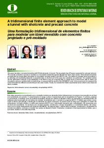
differences across the piezoelectric thickness, piezoelectric layer is divided into two layers. The obtained results from the present method have been compared with results from other researchers in Fig. 5. The proposed model, which ensures continuity condition for the transverse shear stresses, has a high agreement with mixed model of Chee et al. Case II (Three-layer active/sensory cantilever): In order to investigate the sensory capability, a mechanical load of 1000N upwards was applied to the free tip of layered beam. Due to the electro-mechanical properties, a potential difference will appear across the thickness of piezoelectric layer. The mid-plane deflections along the beam and the total voltage across the thickness of the piezoelectric have been plotted in Figs. 6 and 7, respectively. From these figures, the deflection and the voltage distribution predicted by the present formulation have a very good correlation with results of Chee et al. [28]. 5.2
PVDF Bimorph Beam
The second case study is a cantilever piezoelectric bimorph beam with two PVDF layers bonded together and polarized in opposite directions. This particular example and its related dimensions have been shown in Fig. 8. This bimorph beam has been studied by the following researchers: Hwang and Park [36], Tzou and Ye [37], Chee et al. [28], Tzou and Tseng [9], Suleman and Venkayya [38], Correia et al. [39], and Fukunaga et al. [40]. 254
Electric Potential (V)
2500 2000
Sar./Hey. Al Chee et al. Al present Al Sar./Hey. T300
1500 1000
Chee et al. T300 present T300
500 0 0
0.2
0.4
0.6
0.8
1
1.2
Normalized Distance (x/L)
Fig. 7
Voltage difference across the piezoelectric layer
Fig. 8
Piezoelectric bimorph beam
In order to compare the present results with results obtained by these researchers, the following mechanical and piezoelectric properties are used for the PVDF beam: E11 = E22 = E33 = 2GPa, G12 = G13 = G23 = 1GPa, ν12 = ν23 = ν13 = 0.0, e31 = e32 = 0.0460C/m2, and χ11 = χ33 = 0.1062 × 10⁻⁹F/m. The e33 coefficient is assumed to be zero. Also the beam has been discretized into five equal elements for comparison purposes. Case I (Actuator model): By applying a total 1V voltage across the thickness direction, PVDF bimorph beam will act as an actuator. The induced deflections can be found in Table 2. For comparison, the results Journal of Mechanics, Vol. 26, No. 2, June 2010
Comparison of deflections induced by actuators
Location x (mm) Present Mixed model (Chee et al. (1999)) Plate FE (nine-node element) (Fukunaga et al. (2001)) Plate FE (four-node element) (Fukunaga et al. (2001)) Theory (Tzou and Tseng (1990)) Plate FE (11 DOFs) (Correia et al. (2000)) Plate FE (9 DOFs) (Correia et al. (2000)) Shell FE (FDST) (Tzou and Ye (1996)) Plate FE (FDST) (Suleman and Venkaya (1995)) Analytical (Correia et al. (2000)) Experimental (Tzou and Tseng (1990))
(10−4 mm) 40 0.552 0.552 0.553 0.553 0.552 0.552 0.552 0.528 0.55 0.51 −
Deflections 20 0.138 0.138 0.139 0.139 0.138 0.138 0.138 0.132 0.14 0.13 −
obtained from Chee et al. [28], Tzou and Ye [37], Tzou and Tseng [9], Suleman and Venkaya [38], Correia et al. [39], and Fukunaga et al. [40] have been employed. From this table, it can be found that the present results are in very good agreement with previous theoretical and experimental results. Case II (Sensor model): The sensor capability has been investigated in this section. The voltage distribution for an imposed tip deflection of 10mm has been plotted in Fig. 9. In this figure, the present results have been compared with the results obtained from Hwang and Park [36], Chee et al. [28], and Tzou and Tseng [9]. Because Hwang and Park used five pieces of separate electrode, the sensor voltage in Fig. 9 has a step distribution. However, it is possible to measure the sensor voltage using point electrodes. Measuring the sensor voltages via these types of electrodes leads to a sensor distribution as shown by the results of Tzou et al., Chee et al. and the present model. Figure 9 also indicates a good agreement between previous results and the present model.
Voltage Difference across beam (Volts)
Table 2
60 1.242 1.242 1.24 1.24 1.24 1.24 1.24 1.19 1.24 1.14 −
80 2.208 2.208 2.21 2.21 2.21 2.21 2.21 2.11 2.21 2.02 −
100 3.45 3.45 3.45 3.45 3.45 3.45 3.45 3.30 3.45 3.16 3.15
350 300 250 200
Hwang/Park Tzou et al
150
Chee et al. present
100 50 0 0
0.02
0.04
0.06
0.08
0.1
Distance (m)
Fig. 9
Voltage difference across the thickness of PVDF along the length of the cantilever
code whose algorithm is based on the present model has been developed. Comparison of numerical results from this formulation with other published results shows that the present modeling method is suitable in predicting the behavior of laminated beams under mechanical and electrical loadings.
APPENDIX A 6.
CONCLUSIONS
In the present paper, finite element modeling of piezoelectric composite beams with distributed sensor and actuator layers is considered. The variation of mechanical displacement across the thickness has been modeled by a sinus model which ensures continuity condition for the transverse shear stresses as well as the boundary conditions on the upper and lower surfaces of the beam. Any piezoelectric layer in the laminated structure can function as sensor or actuator. This model has the distinct advantage of involving unknowns at the beam mid-plane only. For the electrical potential, the through thickness variation was modeled by the layer-wise theory. The proposed element has the three independent generalized displacements: Two displacements and one rotation. It has C0 continuity, except for the transverse displacement which has C1. A three-layer cantilever beam made of piezoelectric and non-piezoelectric materials and a PVDF bimorph beam have been employed for validation. A computer Journal of Mechanics, Vol. 26, No. 2, June 2010
SINUS MODEL WITH CONTINUITY CONDITIONS [29] A.1
Displacement Field
The beam displacement field is defined as follows: u ( x, z ) = u ( x) + zv( x) + f ( z ) u2 ( x) + g ( z ) v2 ( x) +
( NC ) −1
∑
uic ( x)( z − zi +1 ) H ( z − zi +1 )
i =1
w( x, z ) = w( x)
(A.1)
where u(x), v(x), u2(x), v2(x), uic ( x) , w(x) are the unknown functions. H is the Heaviside function, f (z) and g(z) are defined by ⎧ h ⎛ πz ⎞ ⎪ f ( z ) = π sin ⎜ h ⎟ ⎪ ⎝ ⎠ ⎨ ⎪ f ′( z ) = cos ⎛ πz ⎞ ⎜ ⎟ ⎪⎩ ⎝ h ⎠
⎧ h ⎛ πz ⎞ ⎪ g ( z ) = π cos ⎜ h ⎟ ⎪ ⎝ ⎠ ⎨ ⎪ g ′( z ) = − sin ⎛ πz ⎞ ⎜ ⎟ ⎪⎩ ⎝ h ⎠
255
The transverse shear strain component can be written as:
+
∑
uic ( x) H ( z − zi +1 )
(A.2)
i =1
A.2
Boundary Conditions
(1) σ13 ( z1 ) = 0 ⇔ G (1) ( v( x) + w′( x) + v2 ( x) ) = 0
⇔ v( x) + w′( x) = −v2 ( x)
(A.3)
In the same way, at the top surface z NC +1 = h / 2 ; we have: ( NC ) σ13 ( z = z NC +1 ) = 0 ( NC ) −1 ⎛ ⎞ ⇔ G ( NC ) ⎜ v( x) + w′( x) − v2 ( x) + ∑ uic ( x) ⎟ = 0 i =1 ⎝ ⎠ ( NC ) −1
∑
(A.4)
uic = 2v2 ( x)
i =1
Then, the following relations can be deduced: v( x) = − w′( x) −
1 ( NC ) −1 c ∑ ui ( x) 2 i =1
1 ( NC ) −1 v2 ( x) = ∑ uic ( x) 2 i =1
∑ i =1
w( x, z ) = w( x)
For k ∈ {1, NC − 1}, Eq. (A.8) gives: ⎛ 1 ( NC ) −1 G ( k ) ⎜ f ′( zk +1 ) u2 ( x) + ∑ uic ( x) ( g ′( zk +1 ) − 1) 2 i =1 ⎝ k −1 ⎞ + ∑ uic ( x) ⎟ = G ( k +1) ( f ′( zk +1 ) u2 ( x) i =1 ⎠ ( NC ) −1 k −1 ⎞ 1 + ∑ uic ( x) ( g ′( zk +1 ) − 1) + ∑ uic ( x) + ukc ( x) ⎟ 2 i =1 i =1 ⎠ (A.9)
(G ( k ) − G ( k +1) ) f ′( zk +1 ) u2
(A.5)
u ( x, z ) = u ( x ) − zw′( x ) + u2 ( x) f ( z ) 1 ⎛ 1 ⎞ uic ⎜ − z + g ( z ) + ( z − zi +1 ) H ( z − zi +1 ) ⎟ 2 ⎝ 2 ⎠
⎛ 1 ( NC ) −1 ( k +1) σ13 ( zk +1 ) = G ( k +1) ⎜ f ′( zk +1 ) u2 ( x) + ∑ uic ( x) 2 i =1 ⎝ k −1 ⎞ × ( g ′( zk +1 ) − 1) + ∑ uic ( x ) + ukc ( x) ⎟ i =1 ⎠
Equation (A.9) can be written under the following form:
Substituting Eq. (A.5) in Eq. (A.1), the beam displacement field can be rewritten as: ( NC ) −1
∑
layer (k + 1):
At the bottom surface z1 = −h / 2 ; the following relation must be satisfied:
⇔
⎛ 1 ( NC ) −1 c (k ) ( zk +1 ) = G ( k ) ⎜ f ′( zk +1 ) u2 ( x) + σ13 ui ( x) ( g ′( zk +1 ) − 1) 2 i =1 ⎝ k −1 ⎞ + uic ( x) ⎟ i =1 ⎠
∑
γ13 ( x, z ) = v( x) + w′( x) + f ′( z ) u2 ( x) + g ′( x) v2 ( x) ( NC ) −1
layer (k) :
(A.6)
= G ( k +1) ukc ( x) + (G ( k +1) − G ( k ) ) k −1 ⎛ 1 ( NC ) −1 ⎞ × ⎜ ∑ uic ( x) ( g ′( zk +1 ) − 1) + ∑ uic ( x) ⎟ i =1 ⎝ 2 i =1 ⎠
Finally, a system of NC−1 equations is obtained for the NC−1 unknown functions uic ( x) . This system can be expressed as: [ A][U ] = [ B ] u2
Unknown functions are now used to ensure the continuity conditions at each layer interface.
c where [U ]t = [u1c u2c ...... u NC −1 ] and the coefficients Akl of [A] for k ∈ {1, NC−1} are:
A.3 Continuity Conditions for the Transverse Shear Stress From Eq. (A.6), the transverse shear strain can be expressed as: γ13 ( x, z ) = f ′( z ) u2 ( x) +
( NC ) −1
∑ i =1
+
( NC ) −1
∑
⎛ 1 1 ⎞ uic ( x) ⎜ − + g ′( z ) ⎟ ⎝ 2 2 ⎠
uic ( x) H ( z − zi +1 )
σ ( z = zk +1 ) = σ
256
( z = zk +1 )
l = k : Akl = G ( k ) + G ( k +1)
(
(A.7)
In order to ensure continuity condition for the transverse shear stress, we must have: ( k +1) 13
(
) ( g ′( z + (G ) ( g ′( z
l < k : Akl = G ( k +1) − G ( k )
(A.8)
k +1
( k +1)
l > k : Akl = G ( k +1) − G ( k )
i =1
(k ) 13
(A.10)
) + 1)
)
− G ( k ) g ′( zk +1 )
k +1
) − 1)
while [B] is defined by coefficients:
(
)
Bk = 2 G ( k ) − G ( k +1) f ′( zk +1 )
The solution of this system yields uic ( x) = α i u2 ( x) where coefficients αi are expressed from Journal of Mechanics, Vol. 26, No. 2, June 2010
(G ) (k )
A.4
k =1, NC
; ( zk +1 ; g ′( zk +1 ); f ′( zk +1 ) )k =1, NC −1 .
Final Displacement Field
The final displacement field takes the following form u ( x, z ) = u ( x) − zw′( x) + u2 ( x) f ( z ) ( NC ) −1
∑ i =1
1 ⎛ 1 ⎞ αi ⎜ − z + g ( z ) + ( z − zi +1 ) H ( z − zi +1 ) ⎟ 2 ⎝ 2 ⎠ (A.11)
w( x, z ) = w( x)
Note that in the above equations u2(x) = ψx(x) + w′(x)
REFERENCES 1. Crawley, E. F. and Luis, J., “Use of Piezoelectric Actuators as Element of Intelligent Structures,” American Institute of Aeronautics and Astronautics, 25, pp. 1373−1385 (1987). 2. Tzou, H. S. and Grade, M., “Theoretical Analysis of a Multi-Layered Thin Shell Coupled with Piezoelectric Shell Actuators for Distributed Vibration Controls,” Journal of Sound and Vibration, 132, pp. 433−450 (1989). 3. Wang, B. T. and Rogers, C. A., “Laminate Plate Theory for Spatially Distributed Induced Strain Actuators,” Journal of Composite Materials, 25, pp. 433−425 (1991). 4. Sung, C. K., Chen, T. F. and Chen, S. G., “Piezoelectric Modal Sensor/Actuator Design for Monitoring /Generating Flexural and Torsional Vibrations of Cylindrical Shells,” Journal of Sound and Vibration, 118, pp. 48−55 (1996). 5. Wu, C. P., Syu, Y. S. and Lo, J. Y., “ThreeDimensional Solutions for Multilayered Piezoelectric Hollow Cylinders by an Asymptotic Approach,” International Journal of Mechanical Sciences, 49, pp. 669−689 (2007). 6. Wu, C. P. and Liu, K. Y., “A State Space Approach for the Analysis of Doubly Curved Functionally Graded Elastic and Piezoelectric Shells,” Computers, Materials and Continua, 6, pp. 144−199 (2007). 7. Wu, C. P., Chiu, K. H. and Wang, Y. M., “A Review on the Three-Dimensional Analytical Approaches of Multilayered and Functionally Graded Piezoelectric Plates and Shells,” Computers, Materials and Continua, 18, pp. 93−132 (2008). 8. Allik, H. and Hughes, T. J. R., “Finite Element Method for Piezoelectric Vibration,” International Journal for Numerical Methods in Engineering, 2, pp. 151−157 (1970). 9. Tzou, T. S. and Tseng, C. I., “Distributed Piezoelectric Sensor/Actuator Design for Dynamic Measurement /Control of Distributed Parameter System: A Piezoelectric Finite Element Approach,” Journal of Sound and Vibration, 138, pp. 17−34 (1990). Journal of Mechanics, Vol. 26, No. 2, June 2010
10. Xu, K. M., Noor, A. K. and Tang, Y., “ThreeDimensional Solutions for Coupled Thermo-ElectroElastic Response of Multi-Layered Plates,” Computer Methods in Applied Mechanics and Engineering, 126, pp. 355−371 (1995). 11. Semedo Garcao, J. E., Mota Soares, C. M., Mota Soares, C. A. and Reddy, J. N., “Analysis of Laminated Adaptive Plate Structures Using Layer-Wise Finite Element Models,” Composite Structures, 82, pp. 1939−1959 (2004). 12. Garcia Lage, R., Mota Soares, C. M., Mota Soares, C. A. and Reddy, J. N., “Analysis of Laminated Adaptive Plate Structures by Mixed Layer-Wise Finite Element Models,” Composite Structures, 66, pp. 269−276 (2004). 13. Garcia Lage, R., Mota Soares, C. M., Mota Soares, C. A. and Reddy, J. N., “Modeling of Piezolaminated Plates Using Layer-Wise Mixed Finite Element Models,” Composite Structures, 82, pp. 1849−1863 (2004). 14. Heyliger, P. R. and Saravanos, D. A., “Coupled Discrete-Layer Finite Elements for Laminated Piezoelectric Plates,” Communications in Numerical Methods in Engineering, 10, pp. 971−981 (1994). 15. Saravanos, D. A., Heyliger, P. R. and Hopkins, D. A., “Layer-Wise Mechanics and Finite Element Model for the Dynamic Analysis of Piezoelectric Composite Plates,” International Journal of Solids and Structures, 34, pp. 359−378 (1997). 16. Mitchell, J. A. and Reddy, J. N., “A Refined Plate Theory for Composite Laminates with Piezoelectric Laminate,” International Journal of Solids and Structures, 32, pp. 2345−2367 (1995). 17. Sheikh, A. H., Topdar, P. and Halder, S., “An Appropriate FE Model for Through Thickness Variation of Displacement and Potential in Thin/Moderately Thick Smart Laminates,” Composite Structures, 51, pp. 401−409 (2001). 18. Carrera, E., “Theories and Finite Elements for Multilayered, Anisotropic, Composite Plates and Shells,” Archives of Computational Methods in Engineering, 9, pp. 87−140 (2002). 19. Noor, A. K. and Burton, W. S., “Assessment of Shear Deformation Theories for Multilayered Composite Plates,” Applied Mechanics Reviews, 42, pp. 1−13 (1989). 20. Reddy, J. N., and Robbins, D. H. Jr., “Theories and Computational Models for Composite Laminates,” Applied Mechanics Reviews, 47 Part 1, pp. 147−169 (1994). 21. Di Sciuva, M., “A Refined Transverse Shear Deformation Theory for Multilayered Anisotropic Plates,” Atti Accademia Scienze Torino, 118, pp. 279−295 (1984). 22. Lue, D. and Li, X., “An Overall View of Laminate Theories Based on Displacement Hypothesis,” Journal of Composite Materials, 30, pp. 1539−1560 (1996). 23. Bhaskar, K. and Varadan, T. K., “Refinement of Higher Order Laminated Plate Theories,” American Institute of Aeronautics and Astronautics, 27, pp. 1830−1831
257
24.
25.
26.
27.
28.
29.
30.
31.
32.
33.
258
(1989). Di Sciuva, M., “Multilayered Anisotropic Plate Models with Continuous Interlaminar Stress,” Computers and Structures, 22, pp. 149−167 (1992). Lee, C. Y. and Liu, D., “Interlaminar Shear Stress Continuity Theory for Laminated Composite Plates,” American Institute of Aeronautics and Astronautics, 29, pp. 2010−2012 (1991). Cho, M. and Parmerter, R. R., “Efficient Higher Order Plate Theory for General Lamination Configurations,” American Institute of Aeronautics and Astronautics, 31, pp. 1299−1308 (1993). Reddy, J. N., “A Simple Higher-Order Theory for Laminated Composites,” Journal of Applied Mechanics, Transactions of the ASME, 51, pp. 745−752 (1984). Chee, C. Y. K., Tong, L. and Steven, P. G., “A Mixed Model for Composite Beams with Piezoelectric Actuators and Sensors,” Smart Materials and Structures, 8, pp. 417−432 (1999). Vidal, P. and Polit, O., “A Family of Sinus Finite Elements for the Analysis of Rectangular Laminated Beams,” Composite Structures, 84, pp. 56−72 (2008). Benjeddou, A., “Advances in Piezoelectric Finite Element Modeling of Adaptive Structural Elements: A Survey,” Computers and Structures, 76, pp. 347−363 (2000). Cho, M. and Oh, J., “Higher Order Zig-Zag Plate Theory Under Thermo-Electric-Mechanical Loads Combined,” Composites Part B: Engineering, 34, pp. 67−82 (2003). Cho, M. and Oh, J., “Higher Order Zig-Zag Theory for Fully Coupled Thermo-Electric-Mechanical Smart Composite Plates,” International Journal of Solids and Structures, 41, pp. 1331−1356 (2004). Oh, J. and Cho, M., “A finite Element Based on Cubic Zig-Zag Plate Theory for the Prediction of ThermoElectric-Mechanical Behaviors,” International Journal of Solids and Structures, 41, pp. 1357−1375 (2004).
34. Topdar, P., Chakraborti, A. and Sheikh, A. H., “An Efficient Hybrid Plate Model for Analysis and Control of Smart Sandwich Laminates,” Computer Methods in Applied Mechanics and Engineering, 193, pp. 4591−4610 (2004). 35. Saravanos, D. A. and Heyliger, P. R., “Coupled Layer-Wise Analysis of Composite Beams with Embedded Piezoelectric Sensors and Actuators,” Journal of Intelligent Material Systems and Structures, 6, pp. 350−363 (1995). 36. Hwang, W. S. and Park, H. C., “Finite Element Modeling of Piezoelectric Sensors and Actuators,” American Institute of Aeronautics and Astronautics, 31, pp. 930−937 (1993). 37. Tzou, H. S. and Ye, R., “Analysis of Piezoelastic Structures with Laminated Piezoelectric Triangle Shell Elements,” American Institute of Aeronautics and Astronautics, 34, pp. 110−115 (1996). 38. Suleman, A. and Venkaya, V. B., “A Simple Finite Element Formulation for a Laminated Composite Plate with Piezoelectric Layers,” Journal of Intelligent Material Systems and Structures, 6, pp. 776−782 (1995). 39. Correia, F. V. M., Gomes, M. A. A. and Suleman, A., “Modeling and Design of Adaptive Composite Structures,” Computer Methods in Applied Mechanics and Engineering, 185, pp. 325−346 (2000). 40. Fukunaga, H., Hu, N. and Ren, G. X., “Finite Element Modeling of Adaptive Composite Structures Using a Reduced Higher-Order Plate Theory via Penalty Functions,” International Journal of Solids and Structures, 38, pp. 8735−8752 (2001).
(Manuscript received April 24, 2009, accepted for publication July 28, 2009.)
Journal of Mechanics, Vol. 26, No. 2, June 2010