INSTITUTE OF PHYSICS PUBLISHING
JOURNAL OF NEURAL ENGINEERING
doi:10.1088/1741-2560/2/4/006
J. Neural Eng. 2 (2005) 103–113
A finite-element model of the mechanical effects of implantable microelectrodes in the cerebral cortex Jeyakumar Subbaroyan1, David C Martin1,2 and Daryl R Kipke1,3 1
Department of Biomedical Engineering, University of Michigan, Ann Arbor, MI 48109, USA Department of Materials Science and Engineering, University of Michigan, Ann Arbor, MI 48109, USA 3 Department of Electrical Engineering and Computer Science, University of Michigan, Ann Arbor, MI 48109, USA 2
E-mail:
[email protected]
Received 1 May 2005 Accepted for publication 23 August 2005 Published 11 October 2005 Online at stacks.iop.org/JNE/2/103 Abstract The viability of chronic neural microelectrodes for electrophysiological recording and stimulation depends on several factors, including the encapsulation of the implant by a reactive tissue response. We postulate that mechanical strains induced around the implant site may be one of the leading factors responsible for the sustained tissue response in chronic implants. The objectives of this study were to develop a finite-element model of the probe–brain tissue interface and analyze the effects of tethering forces, probe–tissue adhesion and stiffness of the probe substrate on the interfacial strains induced around the implant site. A 3D finite-element model of the probe–brain tissue microenvironment was developed and used to simulate interfacial strains created by ‘micromotion’ of chronically implanted microelectrodes. Three candidate substrates were considered: (a) silicon, (b) polyimide and (c) a hypothetical ‘soft’ material. Simulated tethering forces resulted in elevated strains both at the tip and at the sharp edges of the probe track in the tissue. The strain fields induced by a simulated silicon probe were similar to those induced by a simulated polyimide probe, albeit at higher absolute values for radial tethering forces. Simulations of poor probe–tissue adhesion resulted in elevated strains at the tip and delamination of the tissue from the probe. A tangential tethering force results in 94% reduction in the strain value at the tip of the polyimide probe track in the tissue, whereas the simulated ‘soft’ probe induced two orders of magnitude smaller values of strain compared to a simulated silicon probe. The model results indicate that softer substrates reduce the strain at the probe–tissue interface and thus may also reduce tissue response in chronic implants.
1. Introduction Neuroprosthetic devices have potential applications in the treatment of several debilitating diseases. Advancements in microelectronics and microelectromechanical systems (MEMS) processing technology have continually improved the functional capabilities of these devices while simultaneously shrinking their sizes, thereby enabling them to be implanted with minimal damage or displacement of only a small volume of tissue. Recent experimental results from our group show that it is possible to obtain long-term 1741-2560/05/040103+11$30.00
neural recording from the cerebral cortex for over a period of four months with 80% or more active electrode sites [4, 5]. Flexible and biocompatible polymer substrates have also been used to obtain chronic neural recordings [3, 6, 7]. Work is underway to modify chronic neural implants as closed loop devices by adding chemical sensing and drug delivering capabilities to them [8–10]. But there still remain several challenges in extending the viability of chronic neural devices to render them useful for prosthetic applications. Neural activities recorded from these devices deteriorate with time ultimately leading to complete loss of activity. The failure
© 2005 IOP Publishing Ltd Printed in the UK
103
J Subbaroyan et al
of the devices could be attributed to, among several factors, changes occurring at the probe–tissue interface. Of particular interest to the neural engineering community is the reactive tissue response surrounding the implant. For instance, the electrical properties of the tissue surrounding the implant site are altered due to an inflammatory response that extends to a few 100 µm around the implant [11]. Research conducted in our lab showed that reduction in the root mean square (RMS) noise in unit recordings correlated with a decrease in resistance of the tissue adsorbed onto the recording sites. Animals with an increased signal-to-noise ratio (SNR) as a result of an active intervention strategy also showed reduced encapsulation resistance and extracellular tissue resistance [12]. There are several factors considered responsible for initiating and maintaining the tissue response. Szarowski et al showed that while the initial injury response (defined as post-implant period of 1 week) was a function of the device dimensions, the sustained injury response (defined as post-implant period of 4 weeks and above) was independent of the device dimensions [13]. The continuous presence of the probe induced the formation of a sheath composed of reactive astrocytes and microglia. Tethering forces from interconnects [14], biocompatibility of the implanted substrate material [15–18] and its chronic contact with the meninges [19] were suspected to be other possible causes for the tissue reaction. The reactive tissue response is also prompted by tissue and blood vessel damage caused by the insertion or by motion of the probe in the brain. The motion of the probe during insertion is caused by ‘brain pulsations’—movements of the brain, due to intracranial pressure changes, with respect to the skull. The pulsations have two distinct frequencies—a fast, low amplitude pulsation synchronous with cardiac pulse and a slow, high amplitude pulsation synchronous with breathing [20]. Surface displacements in anesthetized rats were found to be in the order of 2–25 µm due to respiration and 1–3 µm due to vascular pulsations [21]. However, the pulsations cease to exist when the skull is closed as cerebrospinal fluid (CSF) fills up the voids. In chronic microelectrodes, probe ‘micromotion’—relative displacements of the probe with respect to the brain tissue— could be attributed to forces resulting from rotational acceleration of the animal’s head [22]. ‘Micromotion’ is believed to be the causative factor for tethering forces acting on the probe. Researchers suggest that stiffness of the substrate and the interconnect could translate the tethering forces acting on them into interfacial strains at the probe–tissue interface, hence causing damage to the surrounding brain tissue [23]. Hoogerwerf and Wise [24] observed that tips of the probes with platforms incorporated into the cranium caused more tissue reaction than their ‘free floating’ counterparts. It is also believed that a relatively inflexible probe in the brain microenvironment could cause a shear-induced inflammatory response [25]. This could be due to the large mismatch in the stiffness of the probe substrate and the brain tissue (Young’s moduli of bulk silicon and brain are ∼200 GPa [2] and 6 kPa [1] respectively). Hence, there is a good basis for positing a direct correlation between the strains induced around the implant and the chronic reactive tissue response. 104
Our objectives in this study were to use a model to understand the mechanical strain profiles induced in the tissue as a function of tethering forces, substrate stiffness and probe– tissue adhesion properties. The simulation results suggest that a cause–effect relationship could exist between localized strains at the probe–tissue interface and the sustained tissue response and provide insight into refining the physical probe design. We specifically focused on the microenvironment immediately adjacent to a microelectrode inserted in the cerebral cortex within the context of performance analysis of implantable microelectrode arrays used in research animals [4, 5, 13, 14, 26]. Extension of the work to microelectrode characterization in humans will require modifications to the model to represent material properties of the human brain.
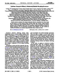
2. Methods 2.1. Finite-element model development A 3D finite-element model of the probe–tissue interface was developed in ABAQUS 6.4 (HKS Inc., RI). The model had two components—a single shank probe and (cortical) brain tissue. Pre-simulation conditions were defined such that the probe was in contact with the brain tissue; i.e., it was assumed that the probe had already been implanted in the tissue and that their surfaces were in contact. Brain tissue was approximated as linearly elastic with isotropic material properties. The probes simulated in this work are implanted in the cerebral cortex of rats, which predominantly comprises gray matter. Prange and Margulies [27] conclude that gray matter is primarily isotropic, with notable anisotropy restricted primarily to white matter. Hence, the isotropy assumption in this study is reasonable. Moreover, Taylor and Miller [28] report that the accuracy of a linear model is within 2% of a nonlinear model for simulated small strains in brain tissue, as in the present study. A quartersymmetry model was simulated because of tissue symmetry about the xz (horizontal), xy (coronal) and yz (sagittal) planes (figure 1(a)). The probe used in the simulations was based on the geometry of a single shank Michigan probe (figure 1(b)). The tapering sidewalls of the Michigan probe were replaced with straight sidewalls in the simulated probe while the tip shape was approximated to a chisel so that symmetry can be exploited (see the appendix for implementation details). 2.2. Selection of region of interest (ROI) in the brain tissue The movement of the probe relative to the tissue may likely destroy healthy, viable cells surrounding the implant. A typical ‘kill zone’ could extend as wide as 60 µm from the implant site [29]. Moreover, the recordable population of neurons for a single electrode site probe lies within a cylinder of radius ∼140 µm [30]. Hence an ROI of 750 µm was chosen in the brain tissue, much greater than the posited ‘kill zone’ and the effective recording distance of a single shank probe. 2.3. Material property of substrates The interfacial strains induced by three substrate materials were investigated. The modeled substrates include (a) silicon,
FEM of mechanical effects of implantable microelectrodes (a)
1 D
(b)
E
by fixing the edges AB, BC (figure 1(a)) and their corresponding mirror images (not shown), thereby allowing no displacement or rotation of the bottom surface. A boundary condition was defined at the back end of the probe (surface DE, figure 1(a)) such that it was displaced by 1 µm, based on Goldstein and Salcman [22]. The surface interaction between the probe and the brain tissue was defined by a master–slave algorithm, with the probe acting as the master surface and the brain acting as the slave surface (see the appendix for details).
123µm
600µm
2
3000µm
100µm
2.5. Simulations
a ‘stiff’ substrate (elastic modulus, E = 200 GPa), (b) polyimide, a ‘flexible’ polymer substrate (E ∼ 3 GPa) and (c) a hypothetical ‘soft’ substrate (E = 6 MPa). Though silicon is the most widely used substrate for microfabricated probes because of its biocompatibility and established processing techniques, efforts are underway to explore alternate substrates for implantable devices. Our group has investigated both silicon and polymer substrates, namely polyimide [3, 4]. Hence, these two substrate materials were simulated along with a third, highly flexible ‘soft’ substrate material to demonstrate the extent of strain relief provided by such a material.
Simulations were designed to evaluate the effect of tethering forces, substrate stiffness and probe–tissue adhesion properties on the interfacial strains at the probe–tissue surface. The origin of the tethering forces is the relative displacement of the brain with respect to the skull. Since the interconnect from the back end of the probe is fixed to the skull, the tethering forces are translated to the probe–tissue interface. A radial tethering force causes longitudinal displacement of the probe while a tangential tethering force causes perpendicular displacement (figure 1). The simulations consisted of an initial step and a functional step. Baseline material properties and boundary conditions (table 2 in the appendix) were assigned in the initial step. To simulate the effects of tethering forces, substrate stiffness and probe–tissue adhesion properties on the brain tissue, material property definitions, surface interactions and boundary conditions were changed in the functional step (table 3 in the appendix). The simulation outputs include principal stress, von Mises stress, displacement and principal strain components. We shall describe our results based on maximum principal strain, which combines the effect of all the axial strains and hence is representative of the events in the space surrounding the implant. Subsequent uses of the term ‘strain’ refer to maximum principal strain induced in the brain tissue.
2.4. Boundary conditions and interactions
2.6. Estimation of elastic modulus of brain tissue
Initial conditions were defined with the probe shank and brain tissue in contact with each other. Tethering forces are caused by rotational acceleration of the head and could result in the probe being displaced parallel or perpendicular to its longitudinal axis. The nomenclature in the paper uses the longitudinal axis of the probe as the frame of reference. Hence, the forces causing parallel and perpendicular displacements of the probe are called radial tethering forces and tangential tethering forces, respectively. The brain is encapsulated by meningeal layers, namely pia mater and dura mater. The brain–meninges complex is in turn encased in the rigid skull while CSF fills the void between the meninges and the cranium. The lower extension of the brain is connected to the spinal cord through the brain stem. Brain movements are thus restricted and hence boundary conditions were defined such that the bottom surface of the tissue was fixed in the simulations, preventing large scale global displacements while allowing local displacements around the implant site. This is accomplished
An in situ brain tissue indentation experiment was performed to estimate the elasticity of the brain tissue. Unlike conventional studies where indentation depths are on the order of few millimeters [31, 32], the depths in this study were confined to few 100 µm to simulate ‘micromotion’. The choice of the indentation depths (200–700 µm) was limited by the resolution of the force sensor. A mechanical indentation system was custom built in our laboratory. Figure 2 shows the schematic of the test set-up. A cylindrical punch with a flat surface was used to indent the brain tissue. A spring loaded, dc–dc linear variable differential transformer (LVDT) (Trans-Tek Inc., CT) was used for force measurement. The punch was rigidly fixed to the LVDT. A linear piezoelectric actuator (M-230.25, Physik Instruments, MA) was used to drive the punch at 1 mm s−1 to five different indentation depths. Motion control was achieved using an external controller (C862 Mercury Controller, Physik Instruments, USA) interfaced with a personal computer. The LVDT-punch assembly was attached to the actuator using an
y A
x
50µm C
z B
33µm
Figure 1. (a) A quarter-symmetry, 3D finite-element model (FEM) of the probe–brain tissue system with edge-biased seeding along the interface. The directions of probe displacements due to tangential (1) and radial (2) tethering forces, applied to surface DE, are shown. Edges AB, BC and their corresponding mirror images (not shown) are fixed allowing no displacement or rotation. (b) Schematic of a single shank Michigan probe (left) and a close-up view of the recording sites and tip shape (right).
105
J Subbaroyan et al
M-230 Piezoelectric Actuator
RS 232 Serial Interface Labview v6
PI C862 Controller LVDT
CPU PI C862 Controller Interface
Spring Indentor SRS Pre-amp NI-DAQ Board
Figure 2. Experimental set-up for measuring instantaneous indentation forces. Table 1. Experimental (n = 8) indentation forces at a punch velocity of 1 mm s−1. Indentation depth (µm)
Estimated force (mN)
230 276 345 460 690
4.3661 ± 0.1618 5.2983 ± 0.1963 6.8573 ± 0.2484 9.3378 ± 0.2642 15.5018 ± 0.2661
M4 set screw. The entire assembly was attached to the probe holder of a digital, stereotaxic instrument (myNeurolab, MO, USA) using a twin series clamp. The output of the LVDT was amplified (dc coupling, low noise, single ended input, gain = 50) using an SR560 low noise voltage preamplifier (Stanford Research Systems, CA). The output was acquired using a data acquisition board (NIDAQ 6035E, 16 bit resolution, 200 kS s−1, National Instruments, TX) and displayed using LabVIEW 6 (National Instruments, TX). Five adult male Sprague-Dawley rats (Charles River Laboratories, MA) weighing 270–305 g were used for the in situ indentation tests. The animals were anesthetized with a mixture of 50 mg ml−1 ketamine, 5 mg ml−1 xylazine and 1 mg ml−1 of acepromazine administered intraperitoneally with an initial dosage of 0.125 ml/100 g of body weight. The depth of anesthesia was regulated by monitoring the heart rate and blood oxygen saturation. Regular supplements of anesthesia at 0.1 ml were administered throughout the surgery. All procedures complied with the guidelines for the care and use of laboratory animals and were approved by the University of Michigan Committee on Use and Care of Animals. The animals were attached to a standard stereotaxic frame. Craniotomies (approximately 7 mm × 2.5 mm) were made on either side of the midline and 1 mm lateral to it. The surface of the brain was kept wet throughout the experiment with liberal application of saline. The punch was manually lowered and placed just above the surface of the brain. The punch was then indented at 1 mm s−1 and the instantaneous peak forces for five indentation depths were obtained. Linear regression coefficient of the force as a function of indentation depth from the in situ experiment was positive and significant (24.2 µN µm−1, p < 0.0001, one-way ANOVA, n = 8). The results are summarized in table 1. 106
In an axisymmetric model where a flat-ended, cylindrical indent is applied perpendicular to the surface of a soft tissue, the resulting indentation force can be used to estimate the elasticity of the tissue under investigation [33]. Using the force values and other experimental parameters in the theoretical model, the elastic modulus was computed to be 5.51 ± 0.3832 kPa. The error between the computed modulus and the simulated modulus was 8.2%. Since the model is linearly elastic, it can be concluded that the model overestimates the strain values by about 8%. The calculated elastic modulus agrees closely with the values obtained by Gefen et al (E = 4.9909 kPa) [31].
3. Results 3.1. Effects of radial tethering force The simulated probe was displaced by 1 µm normal to the surface of the brain tissue and the resulting strain profiles were analyzed. The strain profile had two signature characteristics. First, as shown in figure 3(a), the point of maximum strain occurred at the tip of the probe track in the tissue. There was also a localized high strain area around sharp corners. The other important characteristic was the presence of symmetrical strain areas in the brain tissue along the sidewalls of the simulated probe track resulting from shearing of the tissue and extending up to 100 µm from the implant interface. The strain induced in the nodes located in a direction normal to the longitudinal axis of the probe was plotted at three locations— along the tip, the shank mid-point and near the surface of the brain (see figure 3(b)). Nodal strain values were normalized with respect to the strain observed at the tip of a silicon probe track for comparison between different regions, different substrates and different probe–tissue adhesion properties. Hence a simulated silicon substrate forms the baseline system with which all other results are compared. The strain values at all three positions decrease exponentially as a function of distance from the interface. The strain along the sidewall is due to frictional shear stresses induced by the 1 µm longitudinal displacement or ‘poking’ action of the probe. The shear stress increases from the surface of the brain to the tip of the probe track (figure 4(a)). The radial tethering deformation of the brain tissue could also be compared to crack propagation in brittle materials. The ‘poking’ action of the probe is analogous to mode I or opening
FEM of mechanical effects of implantable microelectrodes (a)
(b) 1
E, Max. Principal (Ave. Crit.: 75% ) 1.540e-02
Surface y =0.9375e− 0.1076x R2 =0.9551
0.5 s
4.834e-07
Normalized strai n
0
m
0.4
0
20
40
60
80 100 Mid−point y =0.3476e−0.0175x R2 =0.9775
0
20
40
60
0.2 0 1
y x z
50µm t
0.5 0
80
100
Tip y =0.8292e−0.0301x 2 R =0.911
0
20 40 60 80 Distance in +x direction(µm)
100
Figure 3. (a) Strain profile in the brain tissue for a radial tethering force resulting in a 1 µm displacement of a silicon probe extended to about 100 µm from the interface (s = surface, m = mid-point and t = tip). Localized high strains occurred at the tip and sharp edges. (b) Normalized strain values decreased exponentially as a function of distance in the brain tissue at all three locations of interest. 0
(b) Stress =k*1/sqrt(r) k =0.3899 2 R =0.9872
0.1
100 200 300 400 500 600 700 800
Mises Stress(nN/µm2)
Distance from the brain surface(µm)
(a)
0.08 0.06 0.04 0.02
900 1000 0.01 0.012 0.014 0.016 0.018 0.02 0.022 0.024 0.026 2 Frictional Shear Stress(nN/µm )
0
20
40
60 80 Distance(µm)
100
120
140
Figure 4. (a) Frictional shear stress increased with the distance from the surface of the brain tissue and was maximum at the tip. (b) von Mises stress has an inverse square root dependence on the longitudinal distance from the tip, analogous to mode I of a crack.
mode of a crack. From basic fracture mechanics, the primary tensile stress in front of the crack tip varies with distance [34], as K k σ = = , (1) (2πr)0.5 (r)0.5 where K is the stress intensity factor, σ is the tensile stress in front of the crack tip and r is the distance from the tip, K k= . (2π)0.5 The von Mises stress data for a radial tethering force when fitted with an inverse square root relation to the longitudinal distance from the tip resulted in an R 2 = 0.9872 (figure 4(b)). This result suggests that a ‘poking’ deformation could lead to extensive compression, or in the worst case, tearing of the tissue underneath the tip. 3.2. Effects of tangential tethering force Theoretical estimates suggest rotational acceleration of an animal’s head can induce lateral tip deflections as large as
20 µm and longitudinal tip displacements along the probe axis around 2 µm [22]. In our model, we used a lateral displacement of 1 µm and found that it induced localized regions of high strain near the tip of the probe track in the brain tissue (figure 5(a)). Symmetrical strain regions along the sidewalls extended away from the implant interface for about 30 µm into the surrounding tissue. As in the radial tethering case, nodal strain values were normalized with respect to the strain at the tip of a silicon probe track. Figure 5(b) shows that the strain falls off exponentially at all the three regions of interest. The pressure profile revealed that the tissue underwent compression near the surface of the brain while there was extensive tension near the tip. 3.3. Effect of probe–tissue adhesion properties Two different adhesion properties were simulated. A good adhesion was defined as zero slip between the tissue and the probe. Such a case would result in frictional shear stresses increasing along the probe–tissue interface from the surface 107
J Subbaroyan et al (a)
(b) 0.3
E, Max. Principal (Ave. Crit.: 75%) 6.511e-03
Surface y =0.2841e− 0.1182x 2 R =0.9851
0.2 0.1
1.661e-07
Normalized strai n
0
0
20
40
60
0
20
40
60
0.3 0.2 0.1 0 1
y x z
80 100 Mid−point y =0.2599e−0.0619x R2 =0.8622
50µm 0.5 0
80
100
Tip y =0.9791e−0.1332x R2 =0.9738
0
20 40 60 80 Distance in +x direction(µm)
100
Figure 5. (a) Strain profile in the brain tissue for a tangential tethering force resulting in a 1 µm displacement of a silicon probe contained to about 30 µm from the interface. (b) Normalized strain values decreased exponentially as a function of distance in the brain tissue at all three locations of interest.
of the brain to the tip of the probe track (figure 5(a)). In contrast, poor adhesion was simulated by defining a finite friction coefficient and elastic slip between the probe shank and the tissue (coefficient of friction = 0.05 and maximum elastic slip = 0.005). Maximal elastic slip was observed near the surface of the brain. The strain profile for poor adhesion, irrespective of the substrate modeled, resulted in increased strains near the tip of the probe track. A radial tethering force, when applied to a poor adhesion case, resulted in a 237% increase in the strain at the tip of the probe track while a tangential tethering force resulted in a 178% increase. As a result of the finite slip, the shear strain along the sidewall was negligible. Both tethering forces resulted in the delamination of the tissue from the probe close to the tip (figure 6).
E, Max. Principal (Ave. Crit.: 75%) 5.187e-02
-2.440e-06
3.4. Effect of substrate stiffness The mismatch in the mechanical properties of the probe substrate and the tissue resulted in large strains at the interface as seen from the above results. The performances of three simulated substrates namely, silicon, polyimide and ‘soft’ material were directly compared in terms of the strains induced at the tip of their track in the brain tissue due to radial and tangential tethering forces. For both forces, simulation results indicated that polyimide and silicon substrate probes produced similar strain profiles extending up to several tens of microns from the implant site, albeit the former had lower absolute values. As observed in the previous cases, the strain values decayed exponentially as a function of distance in the brain tissue for both polyimide and ‘soft’ substrates (figure 7). For a radial tethering force, there was negligible decrease in the strain at the tip of a polyimide probe track whereas there was a 65% decrease in the strain at the tip of a ‘soft’ probe track. A 94% reduction in the strain value at the tip of a polyimide probe track was observed for a tangential tethering force (figure 8(a)). On the other hand, the ‘soft’ probe induced almost two orders of magnitude less strain at the probe tip and mid-point locations. The tangential tethering force resulted 108
50 µm
Figure 6. Poor probe–tissue adhesion could result in compression and delamination of tissue from the probe (encircled region). A scale factor of 100 was used to highlight these events near the tip of the probe.
in extensive flexing and hence increased strain values at the surface of the brain tissue (figure 8(b)). To quantify the amount of strain relief provided by flexible substrates over their stiffer counterparts, we compared their length constants. The length constant was defined as the perpendicular distance from the probe–tissue interface at which the normalized strain fell off to 5%. The values were plotted for both radial and tangential tethering cases (figure 9). As seen from the plot, there was a 4% and 42% decrease in the length constant at the tip of a simulated
FEM of mechanical effects of implantable microelectrodes (a)
Surface
1
(b) 0.6
Silicon Polyimide "Soft"
0.8
Surface
Silicon Polyimide "Soft"
0.4
0.6 0.4
0.2
0.2 0
20 Mid-point
0.4
40
60
80
0.3 0.2 0.1 0
0
20
1
0
100 Normalized Strain
Normalized Strain
0
40
60
80
0.5
0
40
60
80
100
40
60
80
100
20 40 60 80 Distance in +x direction(µm)
100
0.1
0
1
Tip
20 Mid-point
0.2
0
100
0
0.3
20 Tip
0.5
0
20 40 60 80 Distance in +x direction(µm)
0
100
0
Figure 7. Normalized strain values induced by three different probe substrates for displacements resulting from a (a) radial tethering force and (b) tangential tethering force. While a ‘soft’ substrate was effective in providing strain relief against both forces, a polyimide probe provided effective strain relief only against tangential tethering forces. (a)
(b)
E, Max. Principal (Ave. Crit.: 75%) 3.886e-03
E, Max. Principal (Ave. Crit.: 75%) 1.318e-03
2.638e-07
3.818e-09
y
x
50µm
z
Figure 8. Strain profile induced in the brain tissue for displacement resulting from a tangential tethering force by a (a) polyimide and (b) ‘soft’ probe. Note the shift in the region of high strain from the tip (silicon) to the surface of the brain tissue (polyimide and ‘soft’).
polyimide probe and a simulated ‘soft’ probe compared to an equivalent silicon probe for a radial tethering force. The effect is more pronounced for a tangential tethering force. A 90% decrease in the length constant at the tip of a simulated polyimide probe was observed while the strain value observed at the tip of a simulated ‘soft’ probe was negligible.
4. Discussion Finite-element modeling is an excellent analytical tool used in studying the injury biomechanics of soft tissues such as brain
[32, 35]. The use of modeling has enabled the understanding of stresses (strains) induced in the brain tissue during head injury. We have adopted a similar approach in this paper by developing a 3D finite-element model of the probe–brain tissue microenvironment to analyze the effects of tethering forces, probe–tissue adhesion properties and substrate stiffness on the induced interfacial strain profiles. As described in the introduction, the origin of the tethering forces is ‘micromotion’ caused by rotational acceleration of the animal’s head. The effects of two types of tethering forces—radial and tangential—were simulated. We have also investigated the effect of probe–tissue adhesion properties on 109
Length Constant(µm)
Length Constant(µm)
J Subbaroyan et al
140 120 100 80 60 40 20 0
Silicon Polyimide "Soft"
Surface
Mid–Point
Tip
Mid–Point
Tip
60 50 40 30 20 10 0
Surface
Figure 9. Length constants of the three probe substrates for a (a) radial tethering force and (b) tangential tethering force. (∗—Normalized strain less than 5%).
the strain induced in the surrounding brain tissue. A ‘good’ adhesion is defined by a no slip condition between the probe and the tissue while a ‘poor’ adhesion is defined by a finite slip condition (appendix, table 3). These conditions were used to evaluate the effect of integration of the implant in the tissue. Finally, the effect of substrate stiffness on the strain induced was also evaluated. While it was intuitively expected that flexible substrates could result in reduced strain in the tissue, the extent of strain relief had not been quantitatively simulated previously. Moreover, the understanding of the effect of tethering forces and probe–tissue adhesion properties has, at best, been anecdotal until now. In this study, we have quantified the results in each case based on the strain induced and the extent of its influence in the tissue surrounding the implant. The simulation results provide a basis for new design rules for the physical design of this type of probe in order to minimize stresses between the probe and adjacent tissue. Unlike impact injury modeling [36, 37] or modeling surgical procedures [35, 38], this modeling of the brain is different because of the small strain rates (in the order of 10−6 s−1) and small displacements involved (2–20 µm). They are small enough to treat the brain tissue as linearly elastic. The rationale for this choice stems from the fact that the strain rates used in the simulations fall under the instantaneous elastic region of the brain viscoelastic properties. The scope of the model used in this study is thus limited to evaluate the instantaneous elastic responses of the brain tissue to small displacements, and hence time-dependent (viscous) properties are neglected. Time-dependent factors such as velocity of implant ‘micromotion’, creep and fatigue and their effect on the induced strains are not determined by the model. Unlike the model proposed by Miller and Chinzei, the current model assumes identical tissue stiffness in compression and extension [39]. Nonetheless, the results provide insight into the events caused by the mechanical impedance mismatch at the interface of a soft tissue with a rigid implant substrate. The results of the study showed elevated local strains near the tip and edges of the probe. Hence, sharp discontinuities 110
in probe design should be avoided. One method to achieve this is by reducing the opening angle of the tip (defined as half the angle between the faces of the tip). This would result in a smooth gradation of the shank width while avoiding sharp edges. A large mismatch in the mechanical properties between the probe and the tissue (silicon is about 106 times stiffer than brain) exerts pressure on the surrounding tissue. This could result in compression, expansion and even tearing of the tissue. The former two were evident in the nodes near the surface of the brain and surrounding the probe tip. The probe tract in the brain tissue is analogous to a crack on which tensile and compressive stresses are exerted by the probe sidewalls and tip. As seen from figure 4(b), radial tethering forces result in localized high concentrations of tensile (von Mises) stress in front of the probe tip. An increased stress tends to reduce the strength of a material and when this value is exceeded, the crack propagates in a plane normal to the tensile stress. While no attempt has been made to compute the yield strength of the brain tissue or the limiting value of tethering force, the results from figure 4(b) suggest that at yield strength, the tensile stress could result in tearing of the tissue underneath the tip. At all locations along the probe–tissue interface, the strain value dropped exponentially as a function of distance away from the interface. The maximum normalized strain in all cases occurred at the tip. Experimental evidence suggests that an elevated glial fibrillary acidic protein (GFAP) expression, a marker for reactive astrocytes, was observed at the tips of probe arrays [24, 40]. It is possible that the elevated local strains induced by micromotion could be one of the factors responsible for such a response. The strain profile observed along the shank length was due to the shearing of the tissue. It has been shown experimentally that there is strong adhesion between cells and substrate soon after insertion [41]. This could result in the formation of monolayers, and in some cases, multilayers of cells along and on the probe shank. Thus, as the probe was subjected to ‘micromotion’, a considerable amount of shear stress was evident in the vicinity of the implant with a maximum at the tip. The model also showed that dimpling could occur at the surface of the brain. Thus a combination of shearing and compression of the tissue caused by probe ‘micromotion’ could be significant in the case of a relatively ‘stiff’ substrate. This postulation is increasingly being suspected as a major contributor in maintaining the tissue response in chronic implants [14]. Probe–tissue adhesion is believed to be an essential ingredient to obtain stable long-term recordings. While a good adhesion could result in the shearing of the tissue along the interface, it results in smaller strains at the tip compared to a poor adhesion case. Hence a probe that slips into the brain during insertion minimizing shear stresses (poor adhesion) while promoting tissue integration post-insertion (good adhesion) will be an ideal candidate for good long-term recordings. The use of soft polymer coatings could be one of the solutions in realizing such a probe. Poor adhesion could also result in the delamination of tissue from the probe surface. The latter could alter the recording performance (such as signal amplitude and signal-to-noise ratio) and hence the overall performance of the probe.
FEM of mechanical effects of implantable microelectrodes
It has been postulated that a flexible probe is better suited as a chronic implant because of its ability to provide strain relief against forces of ‘micromotion’ between the probe and the tissue [3]. The simulations confirmed that tethering forces acting on a flexible probe induced less strain values in the brain than a stiffer silicon probe. The probe bent substantially near the surface of the brain because of its smaller modulus of elasticity and hence absorbed most of the stress near the backend. This was affirmed by the pressure profiles that indicate the presence of a substantial compressive stress near the surface (data not shown). The substrates used in the simulations are stiffer than the brain tissue and hence the strain induced in the substrates is negligible compared to the strain induced in the brain tissue (data not shown). The difference in the strain profile induced by different substrates in the brain tissue is caused by the difference in their relative displacements along the shank length to an applied force. There exists a gradient in this displacement with the largest displacement seen at the surface and smallest at the tip. This gradient is not very pronounced for a radial tethering force (unless the substrate is extremely flexible) whereas the trend is clearly observable for tangential tethering forces. The smaller the gradient (defined here as the ratio of tip displacement to surface displacement), the smaller is the induced strain. The strain profiles closely mirror this trend. It has to be noted that this ratio is always higher for the brain tissue than for the substrates. This is expected given the compliance of a soft tissue. A probe in the brain subjected to a tangential tethering force is analogous to an off-center type 1 lever with the surface of the brain acting as the fulcrum (pivot), the tethering force as the effort and the bulk brain tissue acting as a uniformly distributed load where the load is larger than the effort. Given the boundary conditions y = 0 and dy/dx = 0, the beam does not deflect or rotate at the fixed end. The tethering force acting on a ‘stiff’ substrate translates into large interfacial strains at the pivot and at the fixed end. On the other hand, extensive flexing of the ‘soft’ substrate near the surface of the brain prevents stress being transferred along the shank and hence there is significant strain near the pivot, but not along the shank or the tip. Polyimide probe provides the intermediate case between silicon and ‘soft’ probes in that the elevated strain was evident at the surface as well as the shank mid-point indicating that the bending was not confined to the surface of the brain. For a simulated ‘soft’ substrate, the strain values near the shank mid-point and the tip are two to three orders of magnitude smaller than the value at the brain surface. The results indicate that flexible substrates such as polyimide (∼3 GPa) or a ‘soft’ material (6 MPa) could be better candidates for chronic implants although a flexible material presents new challenges for insertion and reliable estimation of their depth in the brain tissue. Compared to a radial tethering force acting on a silicon substrate, a tangential tethering force of equal magnitude induces 33% smaller strain values (figure 5(a)). For a flexible substrate such as polyimide, a tangential tethering force results in elevated strains near the surface of the brain (figure 8(a)). Thus the stresses are now concentrated in the superficial
cortical layers (layer I/II), away from tissue layer of interest (layer V) for neuroprosthetic applications. Strains induced by radial tethering forces extend up to about 100 µm into the tissue compared to about 30 µm in the case of tangential tethering forces. Thus, this model implies that for conventionally tethered planar probes, tangential forces are preferable to radial forces. This has practical implications in the probe design and surgical methodology that researchers should also consider. From the length constant values, it can be seen that a flexible substrate such as polyimide, while providing strain relief against tangential tethering forces, is hardly effective against radial tethering forces. While using a ‘soft’ substrate for intracranial applications posing fabrication and insertion challenges, the most effective method is to reduce the tethering force by using flexible interconnects with silicon or polymer substrates [42–46]. Preliminary results from our lab and other labs have shown that eliminating tethering forces altogether results in statistically significant reduction in the GFAP expression around the implant site suggesting that a direct relationship exists between the interfacial strain induced and the inflammatory response [14, 47]. In summary, the proposed design changes include reducing the opening angle of the probe tip, choice of flexible materials for probe substrates and interconnect and use of a soft polymer coating to reduce the shear stresses associated with insertion.
5. Conclusion A 3D finite-element model of the brain was developed to understand the mechanical properties of the probe–tissue interface. Radial and tangential tethering forces result in elevated strain at the tip and shearing along the probe–tissue interface. Poor tissue adhesion properties could result in negligible shear strains but elevated strains at the tip leading to tissue delamination from the probe. A probe fabricated from a substrate less stiff than silicon (such as polyimide) could reduce interfacial strains by 65–94% at the tip when tangential tethering forces are applied. A hypothetical ‘soft’ substrate could reduce tissue strain by two orders of magnitude. This result assumes importance in the wake of experimental verification that tethering causes a substantial increase in the tissue response surrounding the probe [14]. These results imply that the neural probe interface will benefit from softer materials, improved interfacial adhesion and a restriction of tethering forces to the tangential mode.
Acknowledgments The authors would like to thank John Seymour and Matt Johnson of the Neural Engineering Laboratory for their helpful comments on the manuscript. This work was supported in part by grants from NIH/NIBIB (P41 EB-00230–10), the Engineering Research Centers program of the National Science Foundation (EEC-9986866) and NASA Biosciences and Engineering Institute (NNCO4AA21A). 111
J Subbaroyan et al
Table 2. Dimensions and mechanical properties of the materials used in the FE model. Part
Dimensions (mm)
Young’s modulus (N m−2)
Poisson’s ratio
Brain Probe
0.75 (l) × 0.75 (w) × 1.5 (h) Shank width—0.125 Length—1.125 Thickness—0.025
6000 [1] Silicon—200 × 109 [2] Polyimide—2.793 × 10⁹ [3] ‘Soft’—6 × 10⁶
0.45 0.278 0.33 0.33
Table 3. Property definitions and boundary conditions used in the simulations. Effect simulated
Initial step
Radial tethering force Tangential tethering force
x=y=z=0 x = z = 0, y = −1 x=y=z=0 x = y = 0, z = −1 Normal behavior Tangential behavior Good: ‘Hard’ ‘Rough’ Poor: ‘Hard’ ‘Penalty’ Case a: Silicon Case b: Polyimide Case c: ‘Soft’
Probe–tissue adhesion Substrate stiffness
Appendix A finite-element (FE) model of the probe–brain tissue microenvironment was developed in ABAQUS 6.4 (HKS Inc., RI), a commercially available FE package. The model has two parts—a single shank probe and brain tissue. The dimensions and mechanical properties of the materials used in the model are described in table 2. Exploiting the symmetry of the brain tissue and the probe, a quarter-symmetry model was simulated. A quartersymmetry model, while reducing the computational time, increases model accuracy and sensitivity by increasing the mesh density. Edge biased seeding was used along the edges of the probe–tissue interface while global seeding was applied to rest of the model. A bias ratio of 50 and elements per edge of 25 were chosen for the edge biased seeding. Increasing either the bias ratio or elements resulted in non-convergence of simulations even after several hours. A mesh convergence study was carried out and an optimal element size of 15 was chosen for the global seeding. The resulting model had 6996 elements and 31 608 nodes. C3D20R (20 node quadratic brick, reduced integration type) hexahedral elements were used for meshing. The contact surfaces were defined by two interactions— ‘normal’ behavior and ‘tangential’ behavior. ‘Normal’ behavior was always defined as ‘hard’ contact, with no separation on contact. ‘Tangential’ behavior with a ‘rough’ contact or a ‘penalty’ contact were used to simulate good adhesion (no slip between probe and tissue contact surfaces) and poor adhesion (finite slip between probe and tissue contact surfaces, co-efficient of friction = 0.05 and maximum elastic slip = 0.005). The property definitions and boundary conditions used in the simulations are summarized in table 3.
References [1] Ommaya A K 1967 Mechanical properties of tissues of the nervous system J. Biomech. 1 127–38 [2] Pearson G L, Read W T and Feldman W L 1957 Deformation and fracture of small silicon crystals Acta Metall. 5 181–91
112
General static step
Parameter varied Displacement Displacement Surface interaction Material property
[3] Rousche P J et al 2001 Flexible polyimide-based intracortical electrode arrays with bioactive capability IEEE Trans. Biomed. Eng. 48 361–71 [4] Vetter R J et al 2004 Chronic neural recording using silicon-substrate microelectrode arrays implanted in cerebral cortex IEEE Trans. Biomed. Eng. 51 896–904 [5] Kipke D R et al 2003 Silicon-substrate intracortical microelectrode arrays for long-term recording of neuronal spike activity in cerebral cortex IEEE Trans. Neural Syst. Rehabil. Eng. 11 151–5 [6] Metz S et al 2004 Flexible polyimide probes with microelectrodes and embedded microfluidic channels for simultaneous drug delivery and multi-channel monitoring of bioelectric activity Biosensors Bioelectron. 19 1309–18 [7] Takeuchi S et al 2004 3D flexible multichannel neural probe array J. Micromech. Microeng. 14 104–7 [8] Johnson M D et al 2003 Chemical sensing capability of MEMS implantable multichannel neural microelectrode arrays 25th Annual Int. Conf. of the IEEE Engineering in Medicine and Biology Society (Cancun) [9] Chen J K et al 1997 A multichannel neural probe for selective chemical delivery at the cellular level IEEE Trans. Biomed. Eng. 44 760–9 [10] Papageorgiou D et al 2001 A shuttered probe with in-line flowmeters for chronic in-vivo drug delivery The 14th IEEE Int. Conf. on Micro Electro Mechanical Systems (MEMS) [11] Williams J C 2001 Performance of chronic neural implants: measurement, modeling and intervention strategies Biomedical Engineering (Tempe: Arizona State University) [12] Johnson M D, Otto K J and Kipke D R 2005 Repeated voltage biasing improves unit recordings by reducing resistive tissue impedances IEEE Trans. Neural Syst. Rehabil. Eng. 13 160–5 [13] Szarowski D H et al 2003 Brain responses to micro-machined silicon devices Brain Res. 983 23–35 [14] Biran R, Martin D C and Tresco P A 2005 Neuronal cell loss accompanies the brain tissue response to chronically implanted silicon microelectrode arrays Exp. Neurol. 195 115–26 [15] Yuen T G H, Agnew W F and Bullara L A 1987 Tissue response to potential neuroprosthetic materials implanted subdurally Biomaterials 8 138–41 [16] Stensaas S S and Stensaas L J 1978 Histopathological evaluation of materials implanted in cerebral cortex Acta Neuropathol. 41 145–55
FEM of mechanical effects of implantable microelectrodes
[17] Stensaas S S and Stensaas L J 1976 Reaction of cerebral cortex to chronically implanted plastic needles Acta Neuropathol. 35 187–203 [18] Koeneman B et al 2004 An ex vivo method for evaluating the biocompatibility of neural electrodes in rat brain slice cultures J. Neurosci. Methods 137 257–63 [19] Kim Y et al 2004 Chronic response of adult rat brain tissue to implants anchored to the skull Biomaterials 25 2229–37 [20] Britt R H and Rossi G T 1982 Quantitative analysis of methods for reducing physiological brain pulsations J. Neurosci. Methods 6 219–29 [21] Muthuswamy J et al 2003 Microactuated neural probes to compensate for brain micromotion 25th Annual Int. Conf. of EMBS (Cancun) [22] Goldstein S R and Salcman M 1973 Mechanical factors in design of chronic recording intracortical microelectrodes IEEE Trans. Biomed. Eng. 20 260–9 [23] Uwe Meyer J et al 1996 Chronically implantable neural information transducers 18th Annual Int. Conf. of the IEEE Engineering in Medicine and Biology Society (Amsterdam) [24] Hoogerwerf A C and Wise K D 1994 A 3-dimensional microelectrode array for chronic neural recording IEEE Trans. Biomed. Eng. 41 1136–46 [25] Edell D J, Kuzma J and Petraitis D 1996 Tomorrow’s implantable electronic systems 18th Annual Int. Conference of the IEEE Engineering in Medicine and Biology Society (Amsterdam) [26] Nicolelis M et al 2003 Chronic, multisite, multielectrode recordings in macaque monkeys Proc. National Academy of Sciences of the United States of America vol 100 pp 11041–6 [27] Prange M and Margulies S 2002 Regional, directional, and age-dependent properties of the brain undergoing large deformation Trans. ASME, J. Biomech. Eng. 124 244–52 [28] Taylor Z and Miller K 2004 Reassessment of brain elasticity for analysis of biomechanisms of hydrocephalus J. Biomech. 37 1263–9 [29] Edell D J et al 1992 Factors influencing the biocompatibility of insertable silicon microshafts in cerebral cortex IEEE Trans. Biomed. Eng. 39 635–43 [30] Buzsaki G 2004 Large-scale recording of neuronal ensembles Nat. Neurosci. 7 446–51 [31] Gefen A et al 2003 Age-dependent changes in material properties of the brain and braincase of the rat J. Neurotrauma 20 1163–77
[32] Miller K and Chinzei K 1997 Constitutive modeling of brain tissue: experiment and theory J. Biomech. 30 1115–21 [33] Zhang M, Zheng Y and Mak A 1997 Estimating the effective Young’s modulus of soft tissues from indentation tests—nonlinear finite element analysis of effects of friction and large deformation Med. Eng. Phys. 19 512–7 [34] Courtney T H 2000 Mechanical Behavior of Materials 2nd edn (Boston: McGraw-Hill) xviii, p 733 [35] Miller K et al 2000 Mechanical properties of brain tissue in-vivo: experiment and computer simulation J. Biomech. 33 1369–76 [36] Donnelly B R and Medige J 1997 Shear properties of human brain tissue Trans. ASME, J. Biomech. Eng. 119 423–32 [37] Brands D W A, Peters G W M and Bovendeerd P H M 2004 Design and numerical implementation of a 3-D non-linear viscoelastic constitutive model for brain tissue during impact J. Biomech. 37 127–34 [38] Hansen K V and Larsen O V 1998 Using region-of-interest based finite element modeling for brain-surgery simulation Medical Image Computing and Computer-Assisted Intervention—Miccai ’98 vol 1496 305–16 [39] Miller K and Chinzei K 2002 Mechanical properties of brain tissue in tension J. Biomech. 35 483–90 [40] Tresco P A Personal communication with D C Martin [41] Turner J N et al 1999 Cerebral astrocyte response to micromachined silicon implants Exp. Neurol. 156 33–49 [42] Hetke J F et al 2003 3-D silicon probe array with hybrid polymer interconnect for chronic cortical recording 25th Annual Int. Conf. of the IEEE Engineering in Medicine and Biology Society (Cancun) [43] Meyer J et al 2001 High density interconnects and flexible hybrid assemblies for active biomedical implants IEEE Trans. Adv. Packag. 24 366–74 [44] Norlin P et al 2002 A 32-site neural recording probe fabricated by DRIE of SOI substrates J. Micromech. Microeng. 12 414–9 [45] Stieglitz T 2001 Flexible biomedical microdevices with double-sided electrode arrangements for neural applications Sensors Actuators A 90 203–11 [46] Stieglitz T, Beutel H and Meyer J 1997 A flexible, light-weight multichannel sieve electrode with integrated cables for interfacing regenerating peripheral nerves Sensors Actuators A 60 240–3 [47] Subbaroyan J et al 2004 Characterization of the electrode-tissue interface in chronic neural implants 34th Annual Meeting of the Society for Neuroscience (San Diego)
113