Landman, Hoogendoorn, Westerman, Hoogendoorn-Lanser, Van Kooten
1
Design and Implementation of Integrated Network Management in the Netherlands Ir. Ramon Landman Department of Transport & Planning Faculty of Civil Engineering and Geosciences Delft University of Technology Stevinweg 1, PO Box 5048, 2600 GA Delft – The Netherlands phone +31 15 278 39 58 fax +31 15 278 31 79 e-mail
[email protected] Prof. dr. ir. Serge Hoogendoorn (corresponding author) Department of Transport & Planning Faculty of Civil Engineering and Geosciences Delft University of Technology Stevinweg 1, PO Box 5048, 2600 GA Delft – The Netherlands phone +31 15 278 54 75 fax +31 15 278 31 79 e-mail
[email protected] Dr. Marcel Westerman MARCEL Pendrechtseweg 12 3084 NL Rotterdam Phone 06 -18142702 e-mail
[email protected] Sascha Hoogendoorn-Lanser, PhD Rijkswaterstaat, Centre for Transport and Navigation Schoemakerstraat 97c, 2628 VK Delft – The Netherlands phone +31887982483 fax +31887982999 e-mail
[email protected] Jaap van Kooten ARANE Groen van Prinsterersingel 43b, 2805 TD Gouda, The Netherlands phone +31 182 555030 fax +31 182 555039 e-mail
[email protected] Word count Abstract Main text Figures (8 x 250) Total
209 6000 1750 8000
1
Landman, Hoogendoorn, Westerman, Hoogendoorn-Lanser, Van Kooten
2
ABSTRACT Isolated Dynamic Traffic Management (DTM) measures are widely applied means to improve road network performance. It is well known that the uncoordinated deployment of DTM measures can yield suboptimal, perhaps even counterproductive impacts, in particular in case of non-recurrent conditions. Dynamic coordination of DTM measures (Integrated Network Management) is put forward as one of the promising solution directions for efficient utilization of road networks. To investigate the potential of Integrated Network Management in reality, the Dutch Ministry of Transportation has provided a budget of 50 million Euros to set up a large-scale field operational test in which Integrated Network Management is implemented in and around the Dutch city of Amsterdam. The control approach is based on smart integration of established concepts, theories and best practices of (coordinated) DTM and Integrated Corridor Management (ICM). This paper presents an overview of the overall approach with a focus on the developed control framework, based on the principles of escalation, supervision, and graceful degradation. The paper will discuss the main challenges that are to be overcome in order to deploy INM at such large-scale into practice. The paper briefly discusses the evaluation program that is set up to gain insights into the effects on traffic flows, reliability, livability and safety of the designed system. Keywords: dynamic traffic management, integrated network management, field operational test
2
Landman, Hoogendoorn, Westerman, Hoogendoorn-Lanser, Van Kooten
3
INTRODUCTION Isolated Dynamic Traffic Management (DTM) measures are widely applied means to increase road network performance and to increase travel time reliability by synchronizing traffic demand and supply. However, it is well known that the uncoordinated deployment of DTM measures can yield suboptimal, perhaps even counterproductive impacts. In particular in case of non-recurrent conditions (incidents, roadworks, events) coordination between measures is essential to fully utilize the scarce network infrastructure [1]. Dynamic coordination of DTM measures is put forward as one of the most promising solution directions for efficient utilization of road networks. However, despite the many theoretical studies into INM (Integrated Network Management), see [2], only few practical applications of INM can be found [3, 4, 5]. To investigate the potential of INM in reality, the Dutch Ministry of Transportation has provided a budget of 50 million Euros to implement INM in and around the Dutch city of Amsterdam. The overall approach is based on smart integration of established concepts, theories and best practices of (coordinated) DTM and Integrated Corridor Management (ICM). The largescale field operational test will last for about four years, including design and development, implementation and evaluation. It considers the motorways, as well as urban ringroads and arterials. To gain the most benefits for the field trial, the system will be thoroughly evaluated from a traffic operations perspective and an organizational perspective (process of cooperation between road authorities, system implementation, etc.). The results are expected to be of high value for national and international road authorities, researchers, industry, etc., showing under which circumstances and to what extent INM is a cost effective solution for congestion relief. This paper presents an overview of the overall approach with a focus on the developed control framework, which is based on the principles of escalation, supervision, and graceful degradation. This implies that problems are dealt with at the local level if possible, while coordination sets in only when needed. The framework is unique in that it can effectively inhibit multiple proven control paradigms (such as HERO, [6, 7, 8, 9, 10]). Furthermore, local control objectives will be adapted if prevailing problems in the network cannot be resolved by increasing the level of coordination. The paper will discuss the main challenges that are to be overcome in order to deploy INM at such large-scale into practice. The paper furthermore briefly discusses the evaluation program that is set up to gain insights into the effects on traffic flows, reliability, livability and safety of the designed system. Finally, the paper discusses some of the future steps that will be taken in the short term to assure the success of the large-scale trial. STATE OF PRACTICE DTM As mentioned in the introduction, most of the studies on INM are theoretical showing the impact of coordinating available DTM measures using simulation models. Although several examples exist where measures of the same kind are coordinated, a generic framework that allows coordination of heterogeneous measures (route guidance, ramp-metering, intersection control, dynamic speed limits) on a network level is still lacking. In addition to this, many of these theories are not evaluated in a real-life setting, and their direct and indirect effects remain therefore unknown. That said, the concept of INM is certainly not new. Coordination of intersection control has already been performed for decades. In 4th European Framework Program (’94-‘98) the DACCORD study [2] was performed to develop and evaluate coordinated control measures within corridors. Many studies have been performed since then, such as [1]. However, coordination between measures did not find its way to practice on a large-scale yet. Let us consider some of the real-life examples of coordinated traffic management. Traffic control coordination Coordination of traffic lights is one of the most common applications of coordinated traffic control, and practical examples can be found in many places. An older example is the SCOOT system, which was already implemented in practice in 1983. The study of SCOOT implementation carried out in Southampton in 1983 showed journey time-savings of 18% and 26% for the morning and evening peak periods in comparison to Vehicle Actuated control [3]. In a recent study, [11] developed and tested a multi-agent look-ahead traffic-adaptive control system. The project illustrates the development and evaluation of a distributed approach for more efficient and more effective area traffic control. It attempts to solve the shortcomings of
3
Landman, Hoogendoorn, Westerman, Hoogendoorn-Lanser, Van Kooten
4
centralized approaches due to the complexity of the deployed instruments and the frequency with which adjustments have to be made. In addition, the look-ahead adaptive algorithm allows better coordination of actions between neighboring intersections by sharing the information of traffic release from upstream. Both microscopic and macroscopic levels of coordination are considered. Moreover, the performance of the proposed traffic-adaptive control system has been evaluated using a test bed. Coordinated ramp-metering A more recent application of coordination is coordinated ramp-metering. The HERO coordination algorithm was for example successfully applied at the Monash freeway in Australia. The main objectives of this project were: 1. applying a system-wide approach to ramp-metering that would provide the ability to coordinate onramps to balance flows across the network and 2. implementing a system-wide approach for resolving motorway bottlenecks by maximizing the available capacity of the motorway under all traffic loading and environmental conditions. To this aim the system makes use of control logic that supports contemporary traffic flow theory. The assessment of the project showed significant benefits of coordination. HERO sensibly reduced the space-time extent of motorway traffic flow breakdown and provided significant improvements in throughput and travel speed. The AM peak evaluation revealed a 4.7% increase in average flow (on top of the previous system) and a 35.0% increase in average speed while the PM peak evaluation showed an 8.4% increase in average flow and a 58.6% increase in average speed [12, 13]. Need for large field operational test Recently, a state-of-practice review for traffic management was performed by the NEARCTIS Network of Excellence [14]. This report shows, as is illustrated in this section, that the practical studies into the impacts of coordination and integration of DTM measures are still limited. As a consequence, many research questions exist with respect to the design of INM, control concepts to be deployed, technical aspects, expected impacts of the coordination, social costs and benefits, useracceptance, etc. Thus, although large benefits are expected from coordinating DTM measures (in particular under non-recurrent conditions), there is a strong need to investigate these benefits in a real-life, real-size network. TOWARDS INTEGRATED NETWORK MANAGEMENT IN THE NETHERLANDS The goals and frameworks for traffic and transport in the Netherlands to 2020 are described in the ‘Nota Mobiliteit’. To cope with the current and anticipated traffic problems the Nota Mobiliteit presents the ambitious goals: ‘faster, cleaner and safer door to door mobility’. Three interrelated pillars are identified to help realizing these goals knowing: Building road infrastructure, Pricing of infrastructure use, and Utilization of infrastructure. The pillars ‘Building’ and ‘Pricing’ are powerful instruments to solve congestion problems, but they have their limitations in the short term. For one, due to air quality regulation and deferred maintenance building and widening of roads is delayed. Because the implementation of road pricing has been delayed due to technical reasons, and since congestion is still steadily increasing, the Dutch Ministry formulated a clear policy on the transition toward optimal utilization of the Dutch road network by means of DTM in the Framework ‘Utilization’ [15]. This policy is supported by the willingness to structurally invest in DTM, given that we can prove the cost-effectiveness of the measures in general, and in particular of the coordination and integration of measures. This is one of the key motivations that has initiated the large-scale field operational test. LARGE-SCALE FIELD TEST TRAFFIC MANAGEMENT AMSTERDAM In general terms, the main objective of Integrated Network Management is the following: Coordination of local traffic management measures so that the effects on accessibility are such that all stated objectives in a network with collaborating road managers are satisfied as much as possible.
4
Landman, Hoogendoorn, Westerman, Hoogendoorn-Lanser, Van Kooten
5
The large-scale field operational test has as its main objectives: 1. To gather all available (international) theories concerning coordinated DTM in order to come up with and integrated network wide control concept. 2. To develop missing theories so that an overall coordination can be established in practice. 3. To implement the control system at large-scale in practice, overcoming all practical hindrances and challenges that are met (e.g. establishing cooperation between road authorities, specification of new DTM measures and adjusting existing measures to function within an INM frame). 4. Thorough evaluation in practice to gain insights into the feasibility and effects of INM. The results are the basis for political choices in order to structurally support and develop the transition. From these objectives, the following research questions are formulated: 1. How should coordinated network management be designed aimed at improving accessibility on relevant parts of the road network and which measures, control concepts and agreements between road authorities are required to this aim? 2. What are the results of INM expressed in: a. Feasibility in terms of traffic, technical and organizational sense? b. Effects on flows, loss hours, travel times and reliability while taking boundary conditions into account concerning safety, livability and environment? c. Efficiency in terms of social costs and benefits? d. Support from road users and road authorities in the region? 3. What can be learned in respect to national implementation of INM around the main cities? Description of the Amsterdam site The field test area covers about 175 km2. The area has a large number of DTM measures, including over 40 ramp-metering installations and 4 intersection controllers that regulate the inflow towards the motorway, and 75 (variable) message signs. An additional 10 ramp-metering installations will be implemented in the near future (see FIGURE 1). The most important applications that control the current DTM measures are the CDMS (Central VMS Management System – translated from Dutch) for control of Variable Message Signs showing route information and guidance, and the CVMS (Central Intersection controller and ramp-metering Management System – translated from Dutch) for control of intersections and ramp-metering installations. Two traffic control centers are present that monitor the network and distribute traffic information, one for the freeway network, and one for the urban network. Three authorities involved in the large field test: the Ministry of Public Works and Water Management, the Directorate-General for Public Works and Water Management and the Region of Amsterdam.
5
Landman, Hoogendoorn, Westerman, Hoogendoorn-Lanser, Van Kooten
b33
b10
b1
b3 6
b5
VMS for separating local and ongoing flows
Sxx
Static sign for separating local and ongoing flows
Road side information
DW
DWista
VPS
VPS
Sxx b3
b19
b4 b39
b7
VMS for indication calamities
bxx
Existing VMS
bxx
b6
VMS for rerouting traffic
b3
b39
b9
b1
b1
b8
b3
b2
6
DW VPS
DW
b13 b17
b20
b12
b15
b35
b14 b16
b11 b18 bO1
b32 SO4
b27 b29
b21
bO2 b24
VP
S
b30
DW
DW bO3
b23
b31
b22
DW b34 b25
b41
b42
DW
b38 b28
b39
24
b40 DW
Regulation by intersection controller Ramp metering installation Planned for implementation
FIGURE 1 Overview of a) allocation of various types of variable message signs and b) allocation of ramp-metering and intersection controllers that are to be implemented in the INM system.
6
Landman, Hoogendoorn, Westerman, Hoogendoorn-Lanser, Van Kooten
7
Project organization The project covers all above mentioned objectives, elaborated in six different workpackages. If INM turns out to be beneficial from a management and user perspective, the design will be used as a basis for practical implementation in the rest of the Netherlands. Workpackage 1 deals with making an inventory of new DTM measures that are needed to realize INM. Available DTM measures of course serve as a basis to adjust current measures and develop new ones. In workpackage 2 the current measures and applications are actually adjusted and new measures are implemented in practice. In workpackage 3 the concept for an INM system is designed, elaborating the control framework, its components, the control/coordination algorithms and the way policy/sustainability objectives are embedded. A general set up is essential to facilitate implementation elsewhere in the Netherlands. The evaluation is carefully prepared and executed in workpackage 4. To unambiguously evaluate the impacts of INM, a clear evaluation methodology is determined including a description of the performance indicators. To assure the support of all relevant stakeholders everybody works from the same set of objectives, confirmed in a covenant, so that everybody actively participates in realizing the objectives. Clear communication, thorough environmental management and good project management are essential to gain full support in realizing INM. This is taken care of in workpackages 5 and 6. Designing the control system is the most important as well as difficult part of research. Workpackage 3 is therefore the heart of the project, and the other workpackages deliver the essential information and create the right environment to realize the controller design. The remainder of this paper focuses on the design of a control framework that makes use of control units on the level of coordination strings, sub networks and the complete network. INTEGRATED NETWORKWIDE TRAFFIC CONTROL FRAMEWORK This section explains the overall framework developed for the large-scale field operational test Amsterdam. FIGURE 2 provides an overview of this system, including the different logical units, the different levels considered, etc. Let us briefly explain the main elements of the framework. The logical control framework consists of the three key element types: 1. Logical Monitoring Units (LMU) 2. Logical Control Units (LCU) 3. Supervisor Unit (SU) Each of these element types performs specific tasks, which will be explained at an abstract level in the remainder of this section. It is important to understand that all these logical units are defined for multiple clustering levels (see FIGURE 2). The term clustering is used to describe the different levels of coordination needed to solve problems of increasing severity. This is also reflected by the control paradigm used in the large-scale field operational test Amsterdam: ‘solve locally if possible, more globally if needed’. To operationalize this, the following clustering levels of the INM system are defined: 1. Points or local measures 2. Arterials (coordinated measures) 3. Subnetworks (clusters of arterials) 4. Network In doing so, the INM system can incorporate more than coordination of measures along an arterial: also on a higher level, units can be defined that can initiate appropriate action for solving or preventing problems by affecting larger parts of the network. At the same time, hierarchy keeps the complexity of the system at a moderate level. Let us briefly consider the definition and tasks of the logical units. The logical control units influence the traffic flows. They are directly linked to the physical DTM measures (ramp-meter installations, intersection controllers, VMS’s, etc.). The logical control units at the lowest clustering level (points) perform autonomous when problems in the network occur at a local level. When the problems become more severe, the logical control units at a higher level will take over – possibly after intervention of the supervisor – and the level of coordination will increase. Control units are equipped with the proper level of intelligence to communicate with the supervisor unit that guards the performance of the control units, give instructions, and determine when to escalate to a higher
7
Landman, Hoogendoorn, Westerman, Hoogendoorn-Lanser, Van Kooten
8
level of control. From the layer of strings, control units constantly supply the supervision units with their (predicted) control space and the (predicted) effects they can realize. The logical monitoring units monitor traffic operations on the road network at the specific clustering level (point, string, subnetwork, network) at which they are defined. They constantly supply the control units and the supervising unit with information concerning bottlenecks and (storage) capacity in specific parts of the network. To this aim they collect traffic flow data by means of sensors and manipulate the data if needed. Supervisor units aim to find an optimal coordination configuration to solve the problem at hand by combining the information concerning the offered effects of the Logical Control Units (supply) and the required effect identified by the Logical Monitoring Unit (demand). In fact the supervision element is a sort of auction of effects, moreover in the description of the element itself. CONTROL
MONITORING & DIAGNOSIS
SUPERVISION Control rules Control scenarios Control algorithms Event agenda SUPERVISION
ESCALATION In network
Coordinated in network Supervision units
Coordinated in sub network
In Sub networks
Control within layer
Control space Effects
Space Bottlenecks
Coordinated in strings
In strings
Local
At locations
MEASURES
PERFORMANCE
FIGURE 2 Framework for Coordinated Network wide Traffic Control system characterized by the elements CONTROL, SUPERVISION and MONITORING.
Process description There are multiple ways in which the higher control levels – describing higher levels of coordination – in the INM system are activated. Escalation goes gradually if a supervisor notices that a lower level control unit cannot longer solve a certain traffic problem. Assistance will then be granted if there are units available that can have an effect on the specific location in the network by means of redundant control space. The other way is that the control problem is directly escalated to a higher level when a severe traffic problem is detected by a monitoring and diagnosis unit that needs immediate coordination of control units to reduce the negative effects. The determination of an optimal coordination configuration and combination of control settings of the units is done by a supervisor that divides the control tasks over the available units based on their control space, priorities and the distance to the unit in need of assistance. The latter determines how long it takes before the assistance has an effect. The complexity of the search space is reduced by predefinition of fixed combinations of measures. The units no longer function autonomously because they are receiving instructions while constantly being monitored and evaluated by the supervisor. When following instructions the local triggers for escalation are ignored, so complying with instructions always prevails above solving local problems. Escalation example The following example illustrates the escalation process for the ramp-metering installation at connection s106 at the ring west of Amsterdam. The flows on the A10 are steadily increasing at the beginning of the peak hour. To keep the motorway flowing as smooth as possible, the rampmetering installation is spreading out the upcoming platoons from the upstream intersection controller. By means of a short fixed cycle time a constant flow is allowed to enter the motorway.
8
Landman, Hoogendoorn, Westerman, Hoogendoorn-Lanser, Van Kooten
9
As the peak hour advances, the Monitoring & Diagnosis unit will detect decreased flow and speed values due to arising congestion at the designated road stretches. The ramp-metering (RM) installation and Intersection Controllers (IC) subsequently coagulate together so that the RM installation can start restricting the inflow while the upstream IC creates extra waiting space by holding up the traffic (see FIGURE 3). The logical control unit ‘Decreasing inflow to freeway’ determines how long the inflow can be restricted till blockades arise at the connection (indication of control space). Ramp meter Intersection controller Reduced flow toward ramp meter
s106
Urban roads
Freeway, A10
FIGURE 3 Example of coordination between ramp-metering installation and intersection controller.
When the logical control unit runs out of control space, or when congestion appears at the motorway the inflow must be further restricted. To this aim the logical control unit ‘coordination inflow restriction to freeway’ is activated (see FIGURE 4). The unit starts supervising and coordinates the various connections. The upstream connections (e.g. s104, s105, s107 depending on direction) are commanded to help reducing the inflow based on their available control space and priorities. The control space of connections that are marked important in the priority maps are not completely utilized if possible. A10
s104
s105
s106
Autonomous control unit Control unit without control space
s107
Assisting control unit Supervisor for coordination inflow restriction
A4
A10
FIGURE 4 Escalation to higher control level
9
Landman, Hoogendoorn, Westerman, Hoogendoorn-Lanser, Van Kooten
10
LOGICAL CONTROL UNITS Control units are able to influence the traffic flows by means of physical actuators (ramp-metering installations, intersection controllers, VMS’s, etc.). The logical control units are described in terms of their effects, their functioning, the required input, and the output to the supervisor and the actuators. Control units are defined at different levels of coordination (point, string, subnetwork, network). The list below provides a number of examples of the different logical control elements that are considered within the project at different clustering levels. Table 1 Examples of logical control units in the large-scale field operational test Amsterdam Level Point
String
Subnetwork
Network
Logical control unit Facilitating weaving process at merges and weaving areas Reducing inflow from urban network Reducing inflow from urban network while preventing blockades of intersections and off-ramps Create capacity for merging flows by dynamic lane closures Coordinating inflow reductions from on-ramps (e.g. via HERO principles) Improving throughput on major urban corridors while preventing blockades on underlying urban roads Facilitation weaving process by dynamic speed reduction Improving distribution of traffic over lanes by dynamic lane allocation (according to destinations) Improving throughput A10 west by coordinating measures (rerouting traffic over urban ringroad, coordination of inflow reductions from on-ramps, improving throughput on major urban corridors) Improving throughput A10 south by coordinating measures (dynamic lane allocation according to destinations, rerouting city traffic, control inflow from urban network to freeway) Coordination between subnetworks to reduce the collective travel times on selected relations on the freeway by using the resulting network capacity, limiting exchange effects between the freeways and the urban network as much as possible.
The impacts of the logical control units can be expressed at both the traffic operations level and at the policy level. The latter reflects the extent in which the logical control unit can help to achieve the policy objectives described for specific parts of the network. For instance, the A10 freeway has to offer a high service level (speeds higher than 65 km/h); important urban corridors are to operate at speeds higher than 35 km/h, while urban arterials with a regional function are to operate at a speed of at least 25 km/h. An important consequence is that in the control framework itself, the physical entities are less relevant than the logical control units, which are described in terms of functions that cause a certain effect. For instance, ramp-metering installations increase the capacity and reduce the inflow toward the freeway, either autonomously or coordinated, by temporarily holding back traffic on the on-ramp. By coordinating a ramp-meter with the intersection controllers upstream, effectively more traffic can be held back, increasing the duration the ramp-meter can be active without causing blockages. For each of the logical control units, the functions of the unit are described as well as the interfaces. The interfaces relevant are: 1. The acquisition of traffic data from the logical monitoring units 2. The signals going to the physical actuators 3. The input it gets from a higher cluster level (e.g. instructions from the supervisor) 4. The output it returns to the higher cluster level (e.g. the expected effect it will realize, the remaining control capacity) Worked example Let us further clarify these concepts by means of an example. To this end, we will consider the logical control unit ‘Reducing inflow from urban network while preventing blockades of intersections and off-ramps’. FIGURE 5 shows an example of such a control unit. The on-ramp to the A10 freeway (towards the North) is metered. Next to the on-ramp, the relevant directions at the controlled intersections are included in the control process, creating more storage space for the metered vehicles, besides the on-ramp. At the same time, blockades due to the metered on-ramp can be prevented by holding these vehicles back at the controlled intersection, which is beneficial for the other directions.
10
Landman, Hoogendoorn, Westerman, Hoogendoorn-Lanser, Van Kooten
11
Ramp meter Intersection controller (direction toward freeway) Waiting queue at intersection Queue detector
s106
Urban roads
Freeway, A10
FIGURE 5 Logical control unit ‘Reducing inflow from urban network while preventing blockades of intersections and off-ramps’.
This LCU thus has the following objectives: 1. Improving the merging process 2. Prioritize freeway traffic compared to flows from the urban network to the freeway 3. Discourage the use of the freeway by local traffic 4. Reduce traffic volumes on freeway to prevent or solve problems further downstream. This can be achieved via the following functions: 1. Facilitating the merging process by peak shaving (smoothing inflow from the on-ramp) 2. Reduce inflow to the freeway such that the capacity of the freeway (locally, or further downstream) is not exceeded 3. Increase the waiting times for traffic that wants to enter the freeway, making the use of the freeway less attractive to local traffic. To perform these functions, the LCU needs input from the LMU’s that cover the freeway and the urban network at relevant parts: it needs to know the volumes and speeds on the freeway, the length of the queue on the on-ramp, and the length of the queues on the intersections for the relevant directions (compared to the available space on the turning lanes). The output going to the actuators (the ramp-meter and the intersection controllers) are the metering rate, and the maximum lengths of the green phases for the different relations going towards the on-ramp, taking into account the available turning lane space for these directions. From the supervisor, the LCU receives instructions basically describing the effects the LCU will need to cause, and the level-of-service it will need to maintain on the underlying network. This may imply that the traffic conditions in the underlying network will be less than the norm, for instance in case the problems on the freeway are severe. Note that the decision to reduce the admissible level of service will not be made by the LCU, but by the supervisor (as will be illustrated in the remainder). Finally, the LCU will return to the supervisor its control status, the expected effects and its possibilities to keep restricting the inflow to a certain level. LOGICAL MONITORING UNITS In this section, we will describe the logical monitoring units (LMU’s). Similar to the LCU’s, the LMU’s describe monitoring functions rather than physical sensors. The main reason for doing so is the increased flexibility to remove and add new sensors to the system, without changing the entire framework. In other words, in this way the principle of plug and play becomes possible, a very important principle to maintain and adjust the system in the long run and to include pending data collection techniques. The LMU’s continuously monitor the actual traffic situation on the roadway sections in the network. Their function is to recognize bottlenecks and to estimate available space (capacity,
11
Landman, Hoogendoorn, Westerman, Hoogendoorn-Lanser, Van Kooten
12
storage) within the network elements. The monitoring units get their data from assigned sensors (e.g. induction loops or cameras). The LMU’s are defined at different cluster levels (point, string, subnetwork, network). The table below provides a list of examples of LMU’s at the different cluster levels. Note that some of these LMU’s provide directly measureable quantities, while others provide indirect quantities. Table 2 Examples of Logical Monitoring Units. Level Point
String
Subnetwork
Network
Logical Monitoring Unit Traffic volume Traffic point speed Blockage indicator Congestion indicator Waiting time Remaining capacity Distribution over lanes Queue length Waiting time Travel time Remaining capacity / storage capacity in string Disruption and nature of disruption Traffic performance Remaining capacity / storage capacity in subnetwork Total inflow in / outflow from the subnetwork Accumulation (number of vehicles in subnetwork) / average density Traffic performance Remaining capacity / storage capacity in subnetwork Total inflow in / outflow from the subnetwork Accumulation (number of vehicles in subnetwork) / average density
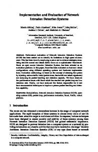
Many of the LMU’s can determine their output based on the sensors that are currently on the Amsterdam freeway and urban network. Flows, speeds and occupancies on the Dutch freeways are monitored by means of induction loops. Travel times are computed from the speed measurements, or are measured directly using dedicated travel time cameras. Worked example: ‘Remaining capacity / storage capacity in a subnetwork’ On the level of sub networks the flow measurements coming from various loop detectors are used to construct performance indicators like Macroscopic Fundamental Diagrams (MFD) that relate average network performance and accumulation. The MFD is a powerful tool to determine the remaining storage space in corridors and subnetworks and therefore it is the main concept behind the LMU ‘Remaining capacity / storage capacity in a subnetwork’ illustrated here. The main functions of the LMU are to determine whether there is a problem in the areas covered by the LMU, and whether there is still capacity available. Note that the former function relates to the level-of-service in terms of traffic operations, and to the desired level of service in the area given the function of the considered road. In other words, both bottlenecks from the traffic engineering perspective are detected as well as bottlenecks from a policy/road function perspective. For subnetworks (but also for strings) the current level-of-service (determining whether there is a problem) is determined by computing (a proxy of) the accumulation, describing the average number of vehicles in the subnetwork. Recall from [16, 17] that the MFD describes a crisp relation between the accumulation and the overall production of a corridor or sub network, for example according the schematized graph in FIGURE 6. The production of the considered network area is derived by weighing the measured flows over the lengths of their roadway stretches. The MFD can be used as an online indicator for the level of service within coordination strings and subnetworks. In this way it is relatively easy to detect any problem and reduction of performance in a qualitative as well as in a quantitative way. If the accumulation is less than the so-called critical accumulation (see FIGURE 6), no problem in terms of traffic operations occurs. When the accumulation is however larger than the critical accumulation, the average network performance will start to decrease and a problem will be identified by the LMU.
12
Landman, Hoogendoorn, Westerman, Hoogendoorn-Lanser, Van Kooten
13
FIGURE 6 Schematized MFD including a level of service indication (colors), the critical accumulation Ncrit and an arbitrary accumulation N at time t giving reason to reduce the inflow into the considered network area in order to control the network back to its critical state.
Clearly, the LMU can also use the MFD – in particular the critical accumulation – not only to determine with how many vehicles the network is overloaded, but also to determine the storage space left in the subnetwork before the performance will deteriorate. The slopes of the free flow and congestion branch give information on respectively how fast the performance of the network becomes instable and how fast it moves toward grid lock. By combining this information with the actual change in accumulation over time a measure can be derived of the time to collapse of the performance of the network given the actual (predicted) inflow. SUPERVISOR The function of the supervisor within the INM system is to ensure that the supply of control effects and the demand for capacity are matched in the best possible way. In this sense, the supervisor is a sort of auctioneer where demands are placed (by the LMU’s) for realizing a certain effect by the LCU’s. Let us in the remainder briefly discuss the functioning of the supervisor elements. The supervisor has four main functions: 1. Safeguarding operations of the LCU’s 2. Escalation of control to higher cluster levels in case lower levels are unable to resolve the prevailing or expected conditions 3. Instructing the LCU’s to achieve certain effects 4. Modify objectives and functions The first function entails checking whether the functioning of the LCU’s is still in line with the boundary conditions formulated for each of the LCU’s, given for instance the priorities that specific parts of the network have over other parts, the function for specific roads, policy objectives, etc. The escalation occurs when the expected effects of the LCU’s at the current level of coordination will not be sufficient to solve the problems at hand. If this occurs, the supervisor will look for the locations where there is space left in the network and for LCU’s (at a higher level) that can – given their expected effects and control space – use that space in the network to effectively resolve the problem. When the supervisor has effectively matched the supply of expected effects of the LCU’s at the higher to the demand for supply reported by the LMU’s, the supervisor will instruct the LCU’s to start performing specific functions to achieve these effects. Finally, when it turns out that there is not sufficient spare capacity left in the network, and none of the LCU’s can resolve the prevailing problems, the supervisor can decide to change the control objectives and functions. This means that the supervisor will decide that the acceptable level-of-service for a specific (type of) road is downgraded based on its function. In doing so, problems on higher-order roads might be resolved (at least to an extent). It may be acceptable that the acceptable level of service on the underlying network is reduced in order to maintain the freeway network flowing. This principle is referred to as ‘graceful degradation’.
13
Landman, Hoogendoorn, Westerman, Hoogendoorn-Lanser, Van Kooten
14
TECHNICAL IMPLEMENTATION In FIGURE 7 an illustrative overview is given of the relevant systems and applications in the traffic control centers of the Directorate-General for Public Works and Water Management and Amsterdam that need adjustments (in red) to realize INM. Weer
Milieu
VK objecten
DGL
Spitsstrook status
Boss Online
VBA
Objecten
I,V,B
Monibas
DSS i/f
DSS
VMC
DSS i/f
DSS Bridge
Vanessa i/f
Dorien proxy
Nina gateway
?? Datex2
Datex2
CDMS CBA
Monica
DynaMax
CTMS Spitsstrook status
CVMS/ HERO
ODA
MOCO
MOZO
DRIP server
VBS
IDP
Rosita
Kantel wals
PVS
MOSW
Doel -> Actie
VRI-C
Doel -> Actie
CVMS
VRI centrale Vialis
Telemelder
VRI centrale Siemens
MTM2 IVERA 0 centrale Siemens
DwiSta
Upgrade
Spitsstrook
Detector
MSG
TDI g1 of g2
TDI g3
Vervang
VRI IV >1.3
VRI IV 0
DRIP
Berm DRIP
Camera
VRI
VRI IV0
VRI >IV 1.3
Berm DRIP
DRIP
Vervang/upgrade
FIGURE 7 Relevant systems and applications in the traffic control centers of the Directorate-General for Public Works and Water Management.
THOROUGH EVALUATION IN PRACTICE The most important deliverables from the evaluation workpackage 4 are the ex-ante evaluation, the workplan of the ex-post evaluation and the actual execution, and the plan to scale up the results to a national level. By means of the ex-ante evaluation insight is gained by means of simulation into the expected effects of INM in the Amsterdam region, resulting in a first estimate of expected social costs and benefits. The evaluation plan describes the applied methods for data collection, data storage and data analysis that are going to be applied for evaluating the true effects of the INM system in practice. Referring to the project objectives, the evaluation must provide insight into the system / technical aspects, the behavioral aspects of the users, the effects on traffic flows and the social effects (travel times, reliability, safety and environment). Therefore, an ex-post social cost benefit analysis is performed in which all above mentioned effects are aggregated and expressed in monetary values. Next to that a large survey will be held under local residents to see if the opinions of the road users support the quantitative evaluation outcomes. To conclude, the plan for implementing INM on a national level describes how a social cost benefit estimation can be made (for INM on national level) on the basis of the ex-post evaluation, the (separate) evaluations of measures that are not tested in the field test (simulation), and the evaluations of measures that are elsewhere implemented (related projects). FUTURE CHALLENGES If INM is beneficial and feasible from the cost benefit and technical analyses, and the support is gained of important stake-holders, then realization of the field operational test will be initiated. This will deliver unique knowledge and practical insights into the achievable effects of INM and its organizational embedment. First of all local infrastructural changes (i.e. changes to the lay out of weaving sections and interchanges) are implemented and evaluated to limit conflicts within the traffic streams and to increase the capacity of the network as much as possible. Then the local measures are further assessed and worked out. The total inflow from the urban roads to the motorway will become controlled by means of ramp-metering installations. Standard coordination is designed between the ramp-metering installations and upstream intersection controllers so that they work as one DTM measure. Alternative control strategies are evaluated like making space for merging traffic flows by closing the right lane for the mainstream upstream the weaving sections. To conclude the adjustments on local level, a first step is made into introducing priority maps into local DTM measures. Roads or tracks with high priority obviously will be favored over low priority roads. At the level of coordination strings, ramp-meters will be coordinated in order to delay the formation of congestion and reduce spill back of on ramp queues to the urban roads (HERO). Inflow limitations are introduced for crossing roads at the intersections with the important corridor
14
Landman, Hoogendoorn, Westerman, Hoogendoorn-Lanser, Van Kooten
15
radials. Weaving processes are improved by dynamical changes of speed limits. Extra capacity is offered between interchanges by dynamic activation of peak lanes. Local traffic and through going traffic are separated by assigning designated lanes. To conclude, variable message signs will actively inform about route alternatives between interchanges to optimally distribute traffic over available routes. On the level of sub networks, the use of the motorway for short trips will be discouraged by imposing extra waiting time at ramp-metering installations. Coordination between rampmetering installations will limit the formation of congestion as long as possible on the motorway and variable message signs must distribute traffic flows equally over the available routes. It is important that road users receive at all time consistent and reliable information and that measures control the traffic in an understandable and reasonable manner. If not, the control system will lose its credibility which will cause public resistance. Next to that, measures like rerouting will lose their effect. SUMMARY AND CONCLUSIONS This paper has introduced the large-scale field operational test Integrated Traffic Management Amsterdam, which is a unique project investigating the potential of coordination and integration of Dynamic Traffic Management measures in a real-life network. The main objectives of the project are primarily to gain insight into the added benefits of integrating traffic management measures, compared to measures operating in an isolated way, primarily focusing on traffic related impacts. In the paper, the motivation for the project and its objectives were discussed. The focus was however on the control framework, based upon the concepts of escalation, supervision, and graceful degradation, and distinguishing three main logical elements: the logical control unit, the logical monitoring unit, and the supervisor. The control framework furthermore distinguishes between different levels of coordination (or clustering), describing to which extent measures will be clustered to form a so-called local control unit. They can be isolated, clustered in a string, clustered in a subnetwork, or clustered in the entire network. The implied hierarchical structure of the control framework causes the complexity of the resulting control problem to remain limited. Furthermore, problems occurring are dealt with first at the location at which they occur. Only if they are (predicted to be) unsolvable, the problem is escalated to a higher level. The control framework will be ‘plug and play’: new sensors can be easily implemented, new control concepts operating at specific clustering levels can be easily included, etc., yielding a very flexible system. In doing so, the system will keep on consisting of state-of-the-art elements. After the project has started and the new control paradigms are implemented, the results of coordination will be closely monitored using a thoroughly designed monitoring program. We are convinced that the new insights will be very valuable for traffic management practice and research.
15
Landman, Hoogendoorn, Westerman, Hoogendoorn-Lanser, Van Kooten
16
REFERENCES 1.
2.
3.
4.
5.
6. 7. 8.
9.
10. 11. 12. 13.
14. 15.
16.
17.
Zhou, X., H.S. Mahmassani and K. Zhang. Dynamic micro-assignment modeling approach for integrated multimodal urban corridor management. Transportation Research Part C, Vol. 16, 2008, pp 167-186. Thijs, R., Ch.D.R. Lindveld, N.J. Van Der Zijpp, and P.H.L. Bovy. Impact assessment of traffic control on motorway corridors: evaluation results from the DACCORD-project, VK 2205.334, Delft University of Technology, 2009. TRG - Transportation Research Group. SCOOT in Southampton: Evaluation of SCOOT in Portswood/St. Denys Area. Technical Report prepared for Hampshire County Council, university of Southampton, 1984. Haj-Salem, H. and M. Papageorgiou. Ramp-metering impact on urban corridor traffic: Field results. Transportation Research Part A: Policy and Practice, Vol. 29, 1995, pp 303319. Haj-Salem, H., J. M. Blosseville and M. Papageorgiou. ALINEA - A Local Feedback Control Law for on-ramp-metering: A real life study. 3rd IEE Intern. Conf. on Road Traffic Control, London, U.K., 1990, pp 194-198. Papageorgiou, M., H. Haj-Salem and J. M. Blosseville. ALINEA: A Local Feedback Control Law for on-ramp-metering. Transportation Research Record 1320, 1991, pp 58-64. Papageorgiou, M., Haj-Salem, H. and F. Middelham. ALINEA local ramp-metering: Summary of field results. Transportation Research Record 1603, 1997, pp 90-98. Papageorgiou, M., M. Ben-Akiva, J. Bottom, P.H.L. Bovy, S.P. Hoogendoorn, N.B. Hounsell, A. Kotsialos, and M. McDonald. Chapter 11 ITS and Traffic Management. Handbooks in Operations Research and Management Science, Vol. 14, 2007, pp 715-774. Hoogendoorn, S.P., W. Daamen, and Y. Yuan. Ex-ante evaluatie gecoördineerde toeritdosering Amsterdam: Tuning, evaluatie en aanpassing van het HERO algoritme. Delft, Netherlands, 2009. Yuan, Y. Coordination of Ramp-metering Control in Motorway Networks, Master thesis, ITS Edulab, Delft, Netherlands, 2008 Van Katwijk, R.T. Multi-Agent Look-Ahead Traffic-Adaptive Control, PhD. Thesis, Delft University of Technology, 2008. Papamichail, I. M. Papageorgiou. Traffic-responsive linked ramp-metering control. IEEE Transactions on Intelligent Transportation Systems, 9, 2008, pp 111-121. Papamichail, I., A. Kotsialos, I. Margonis, and M. Papageorgiou. Coordinated rampmetering for freeway networks – A model-predictive hierarchical control approach. Transportation Research Part C, In press, 2009. European Commission, NEARCTIS – Review of available case studies and related scientific knowledge. 7th Framework Programme, Theme 3, Deliverable 7, 2009. Dutch Ministry of Transport, Public Works and Water Management. Beleidskader Benutten. Eén van de pijlers voor een betere bereikbaarheid. Achtergronddocument (in Dutch). Ministerie van Verkeer en Waterstaat, Directoraat Generaal Personenvervoer, 2008. Daganzo, C.F.,N. Geroliminis. An analytical approximation for the macroscopic fundamental diagram of urban traffic. Transportation Research Part B, Vol. 42, 2008, pp 771-781. Geroliminis, N., C.F. Daganzo. Existence of urban-scale macroscopic fundamental diagrams: Some experimental findings, Transportation Research Part B, Vol. 42, 2008, pp 759-770.
16