Hindawi Publishing Corporation Mathematical Problems in Engineering Volume 2015, Article ID 952049, 11 pages http://dx.doi.org/10.1155/2015/952049
Research Article A Force Sensorless Method for CFRP/Ti Stack Interface Detection during Robotic Orbital Drilling Operations Qiang Fang,1 Ze-Min Pan,1 Bing Han,2 Shao-Hua Fei,1 Guan-Hua Xu,1,3 and Ying-Lin Ke1 1
The State Key Laboratory of Fluid Power Transmission and Control, College of Mechanical Engineering, Zhejiang University, Hangzhou 310027, China 2 AVIC Xi’an Aircraft Industry (Group) Company Ltd., Xi’an 710089, China 3 Kunshan Industrial Technology Research Institute Co., Ltd., Kunshan 215347, China Correspondence should be addressed to Ze-Min Pan;
[email protected] Received 27 March 2015; Accepted 10 August 2015 Academic Editor: Robert Gao Copyright © 2015 Qiang Fang et al. This is an open access article distributed under the Creative Commons Attribution License, which permits unrestricted use, distribution, and reproduction in any medium, provided the original work is properly cited. Drilling carbon fiber reinforced plastics and titanium (CFRP/Ti) stacks is one of the most important activities in aircraft assembly. It is favorable to use different drilling parameters for each layer due to their dissimilar machining properties. However, large aircraft parts with changing profiles lead to variation of thickness along the profiles, which makes it challenging to adapt the cutting parameters for different materials being drilled. This paper proposes a force sensorless method based on cutting force observer for monitoring the thrust force and identifying the drilling material during the drilling process. The cutting force observer, which is the combination of an adaptive disturbance observer and friction force model, is used to estimate the thrust force. An in-process algorithm is developed to monitor the variation of the thrust force for detecting the stack interface between the CFRP and titanium materials. Robotic orbital drilling experiments have been conducted on CFRP/Ti stacks. The estimate error of the cutting force observer was less than 13%, and the stack interface was detected in 0.25 s (or 0.05 mm) before or after the tool transited it. The results show that the proposed method can successfully detect the CFRP/Ti stack interface for the cutting parameters adaptation.
1. Introduction As carbon fiber reinforced plastics and titanium (CFRP/Ti) stacks are widely used in aircraft structures, a large number of bolt holes are required to assemble the stacked structure. Drilling of CFRP/Ti stacks becomes one of the most important activities in the integration of these advanced materials into aeronautical applications. To improve the manufacturing process and achieve high efficiency, the preferable practice is to drill the hole for assembly through CFRP/Ti stacks in one shoot instead of through CFRP and titanium material separately [1, 2]. However, the hard-to-machine properties as well as the dissimilar machining properties of each material make it challenging to drill CFRP/Ti stacks. A number of studies, machining CFRP [3, 4] or Ti [5, 6], have been carried out in the last few decades. On the one hand, low feed rate with high cutting speed is desirable for drilling CFRP material [7, 8]. On the other hand, the optimum drilling process for titanium requires drilling at low cutting speed with moderate feed rate
due to its low thermal conductivity, high hardness/strength, and strong affinity [1, 2, 9]. Therefore, it is not easy to select suitable parameters that perform ideally for both materials in a stacked form. Some of the studies were dedicated to selecting compromised process parameters to drill holes in both materials of the stack [2, 10–12]. Yet some researchers studied tool wear mechanisms, hole qualities, manufacturing cost, and so forth, when drilling the CFRP/Ti stacks, and they changed the parameters during drilling process and applied the most suitable parameters for each material [4, 5, 13]. Changing the process parameters for each material during the drilling process seems a good method to overcome the compromise of the different machining parameters. But large aircraft parts are usually designed with changing profiles and the thickness of different material layers varies along the profiles. In addition, it is difficult to guarantee the thickness accuracy of the large CFRP parts in the fabrication process. Therefore, it is a challenge to achieve the adaptation of the cutting parameters for different materials since
2 the thickness of each layer is unknown. Neugebauer et al. [14] presented a method based on an acoustic emission (AE) signal for identifying the transition point between materials, such that the point can be used to correctly adapt the process parameters to the material being drilled. Similar to Neugebauer’s method, researchers conventionally monitor tool/cutting condition by laser, vision sensor, acoustic emission sensor (AE sensor), dynamometer, and so forth [15]. However, these techniques need to install additional sensors and equipment to a machine tool. Considering the cost, workspace limitation, and unwanted compliance, a sensorless method is more favorable in practical applications. Compared with the AE signal, cutting force is a more intuitive characteristic parameter in cutting process, because the variation of cutting force is directly related to the cutting condition (such as tool breakage and tool wear). Thus, realtime information of the cutting force is particularly useful for tool wear prediction, breakage detection, and other malfunction inspections [16]. For these reasons, a force sensorless method based on force observer has been employed by many researchers, because the input of the observer can be obtained from the servo driver directly. The force observer estimates the external force to the servo motor based on the given dynamic system model with the inputs of the measured servo motor current, command position, and actual position [17, 18]. This method is employed to monitor tool collision [19, 20], detect tool wear and failure [21, 22], and suppress the chatter vibration [23]. In the robotic orbital drilling process, the thrust force usually ripples in orbital rotation frequency [24], the amplitude of the ripple force is time varying, and the phase is uncertain when drilling CFRP/Ti stacks. An adaptive observer [25, 26] could be used to obtain the DC component of the thrust force from the complicated signals of the feed drive system. And the estimation consistency, antinoise performance, and convergence rate of the adaptive observer are improved by using the algorithm with exponential forgetting factor [27]. In this paper, a force sensorless method based on cutting force observer is utilized for monitoring the thrust force and identifying the drilling material during the drilling process. An adaptive disturbance observer with exponential forgetting factor, which filters out the undesired force ripple and severe current disturbance of the feed motor, is used to estimate the disturbance force of the feed drive system. The thrust force is calculated by deducting the friction force from the estimated disturbance force. Then, an in-process algorithm is developed to detect the stack interface between the CFRP and titanium materials by monitoring the variation of the thrust force for adapting the cutting parameters. Section 2 describes the dynamic model of the feed drive system for the robotic orbital drilling end-effector. Section 3 presents the adaptive observer employed by the force observer. Section 4 states the design of the interface detecting algorithm which contains a signal processing and a decision making part. Experimental results presented in Section 5 show the effectiveness of the proposed method. Finally, in the last section, the paper concludes with a short summary.
Mathematical Problems in Engineering
Spindle Slide table
Motor Ball screw
Nut
Linear encoder
Robot
Figure 1: Configuration of feed drive system.
2. Dynamics of the Feed Drive System This paper proposes a force sensorless method based on an adaptive disturbance observer of the feed drive system for thrust force monitoring during the orbital drilling process. Before discussing the adaptive disturbance observer, the feed drive system used for the orbital drilling device is introduced first. The system which illustrates a typical configuration of an industrial servo system is depicted in Figure 1. The system comprises a servo motor, a ball screw, a linear encoder, a slide table, and so forth, as shown in Figure 1. The dynamics of the motor can be described by 𝐽𝑒 𝜔̇ 𝑚 = 𝜏𝑚 − 𝜏𝑑 ,
(1)
where 𝐽𝑒 denotes the equivalent inertia of the moving parts, 𝜔𝑚 is the angular velocity, and 𝜏𝑚 and 𝜏𝑑 are the output moment and torque disturbance of the motor, respectively. The motor output 𝜏𝑚 is given simply as 𝜏𝑚 = 𝐾𝑇 𝐼𝑚 ,
(2)
where 𝐾𝑇 is the torque constant and 𝐼𝑚 the motor torque current. The disturbance contains reaction torque 𝜏ext of the cutting process, Coulomb friction 𝜏cf , viscous friction 𝐷𝜔𝑚 (𝐷 denotes the viscous friction constant), and unspecified parameter errors. The disturbance torque on the motor side 𝜏𝑑 is defined as 𝜏𝑑 = 𝜏ext + 𝜏cf + 𝐷𝜔𝑚 + Δ𝐽𝑒 𝜔̇ 𝑚 − Δ𝐾𝑇 𝐼𝑚 ,
(3)
where Δ𝐽𝑒 = 𝐽𝑒 − 𝐽en , Δ𝐾𝑇 = 𝐾𝑇 − 𝐾Tn represent the deviation between the nominal and actual value of the equivalent inertia and torque constant, respectively, and 𝐽en , 𝐾Tn are the nominal values.
Mathematical Problems in Engineering
3
In the case that Δ𝐽𝑒 and Δ𝐾𝑇 equal zero, (3) can be simplified as 𝜏𝑑 = 𝜏ext + 𝜏cf + 𝐷𝜔𝑚 .
(4)
Plant 𝜏d Im
+ −
KT
1 Je s
𝜏m
𝜔m
xact
Kpitch s
The estimation of torque disturbance is derived as 𝜏̂𝑑 = 𝐾Tn 𝐼𝑚 − 𝐽en 𝜔̇ 𝑚 .
(5)
Im
The estimated cutting force is obtained as 𝐹̂cut =
𝑛 (̂ 𝜏 − 𝜏cf − 𝐷𝜔𝑚 ) , 𝐾pitch 𝑑
where 𝐾pitch and 𝑛 denote the pitch and transmission efficiency of the ball screw, respectively. Preliminary experimental results of the robotic orbital drilling process have shown that the thrust cutting force mainly contains a DC component and an AC ripple force in orbital rotation frequency after being filtered by a low-pass filter, which is also shown in [24]. Thus, the thrust force can be written as 𝐹cut = 𝐹DC + 𝐹𝑟 ,
(7)
where 𝐹DC and 𝐹𝑟 denote the DC component and ripple force, respectively. The frequency of the ripple force equals the orbital frequency which is given by the process parameters within the range from 1 Hz to 4 Hz. It brings trouble when we monitor the value of thrust force to detect the tool position in the drilling process. The frequency of the ripple force is determined by the orbital speed of the orbital drilling operation, but the amplitude and initial phase are uncertain. For this reason, we use an adaptive observer to decouple the ripple force from the observed force. The ripple force can be modeled as 𝐹𝑟 = 𝐹am sin (2𝜋 ⋅ 𝑓orbital 𝑡 + 𝜑ph )
(8)
= 𝑆 ⋅ sin (2𝜋 ⋅ 𝑓orbital 𝑡) + 𝐶 ⋅ cos (2𝜋 ⋅ 𝑓orbital 𝑡) , where 𝑓orbital is the orbital frequency, 𝐹am and 𝜑ph represent the amplitude and initial phase of the ripple force, respectively, 𝑆 and 𝐶 are unknown weights related to 𝐹am and 𝜑ph , and 𝑡 denotes current time. The DC component of the thrust force can be estimated as in the following equation and Figure 2: 𝐹̂DC =
𝑛 𝐾pitch
𝜏̂dc =
𝑛 𝐾pitch
(̂ 𝜏𝑑 − 𝜏cf − 𝐷𝜔𝑚 ) − 𝐹𝑟 .
(9)
Figure 2 depicts the feed drive system and the adaptive cutting force observer. It is assumed that the load torque remains constant and that its derivative equals zero during a few sampling periods since the sampling frequency of the signal processor is much higher than that of the external load torque variation. Thus, 𝑑𝜏𝑑 = 0. 𝑑𝑡
(10)
xact
Friction force model
(6)
̂ DC F
−
xact
Adaptive disturbance observer
FDC +
n (𝜏 + D𝜔m ) Kpitch cf
+ Adaptive cutting force observer
Figure 2: Adaptive cutting force observer of the feed drive system.
The state equation is given by 𝑥̇ (𝑡) = 𝐴 (𝑡) 𝑥 (𝑡) + 𝐵 (𝑡) 𝑢 (𝑡) + Ψ (𝑡) 𝜃 + 𝛿 (𝑡) , 𝑦 (𝑡) = 𝐶𝑥 (𝑡) + 𝜂 (𝑡) ,
(11)
where 𝑇
𝑇
𝑥 (𝑡) = [𝑥1 𝑥2 𝑥3 ] = [𝑥act 𝜔𝑚 𝜏𝑑 ] , 𝑦 (𝑡) = 𝑥act , 𝑢 (𝑡) = 𝐼𝑚 , 0 𝐾pitch 0 [ 1 ] ] 𝐴 (𝑡) = [ [0 0 − ] , 𝐽en 0 ] [0 0
(12)
𝑇 𝐾 𝐵 (𝑡) = [0 Tn 0] , 𝐽en 𝑇
1 0 sin (𝑓obital 𝑡) 0 [ Ψ (𝑡) = − ] , 𝐽en 0 cos (𝑓obital 𝑡) 0 𝑇
𝜃 = [𝑆 𝐶] , 𝐶 (𝑡) = [1 0 0] . The input variable 𝑢(𝑡) is the motor drive current 𝐼𝑚 , state variables 𝑥(𝑡) are the actual position 𝑥act of the slide table, motor angular velocity 𝜔𝑚 , and the disturbance torque 𝜏𝑑 , the output variable 𝑦 is equal to 𝑥act , and 𝛿(𝑡) ∈ 𝑅𝑛 and 𝜂(𝑡) ∈ 𝑅𝑚 are the system noise and the measurement noise, respectively. 𝑄(𝑡) ∈ 𝑅𝑛×𝑛 and 𝑅(𝑡) ∈ 𝑅𝑚×𝑚 are their covariance matrices. In order to simplify the expression, the symbol 𝑡 will be omitted in the following equations unless there is an emphasis.
4
Mathematical Problems in Engineering ̇ Suppose the relationship between 𝜃̂ and system output estî is mation error (𝑦 − 𝑦)
3. Adaptive Observer with Exponential Forgetting Factor For any given parameter 𝜃, a state observer for system (11) can be designed as
̇ ̂ , 𝜃̂ = 𝑀 (𝑡) (𝑦 − 𝑦)
̂̇ = 𝐴𝑥̂ + 𝐵𝑢 + Ψ𝜃 + 𝐾 (𝑦 − 𝐶𝑥) ̂ , 𝑥
where 𝑀(𝑡) ∈ 𝑅𝑝×𝑚 is an undetermined parameter. Due to 𝜃̃ = 𝜃 − 𝜃̂ and 𝜃̇ = 0, thus
(13)
where 𝑥̂ is the estimation of the system state 𝑥 and 𝐾(𝑡) is the gain matrix. Since 𝜃 is unknown in system (11), 𝜃 is replaced by its ̂ Therefore, the state observer (13) is written as estimate 𝜃(𝑡). ̂̇ = 𝐴𝑥̂ + 𝐵𝑢 + Ψ𝜃̂ (𝑡) + 𝐾 (𝑦 − 𝐶𝑥) ̂ + 𝑤 (𝑡) , 𝑥
(14)
̂ where 𝑤(𝑡) denotes the deviation of the estimated value 𝜃(𝑡) from the true value 𝜃, and it will be explained later. Define the estimate errors of the state 𝑥 and unknown parameter 𝜃 as 𝑥̃ (𝑡) = 𝑥 (𝑡) − 𝑥̂ (𝑡) , 𝜃̃ (𝑡) = 𝜃 (𝑡) − 𝜃̂ (𝑡) .
(15)
As parameter 𝜃 is a constant, hence, 𝜃̇ = 0. Combining (11), (14), and (15), the derivative of estimate error of the state is obtained as ̃̇ = 𝑥̇ − 𝑥 ̂̇ 𝑥 = 𝐴𝑥 + 𝐵𝑢 + Ψ𝜃 ̂ + 𝑤] − [𝐴𝑥̂ + 𝐵𝑢 + Ψ𝜃̂ + 𝐾 (𝑦 − 𝐶𝑥)
(16)
̇ ̃ 𝜃̃ = −𝑀𝐶̃𝑧 − 𝑀𝐶Υ𝜃.
(24)
As mentioned 𝑧̃(𝑡) → 0 when 𝑡 → ∞, so an appropriate parameter 𝑀(𝑡) would satisfy the remaining expression of (24): ̃𝜉̇ = −𝑀𝐶Υ𝜉, ̃
(25)
stable. Thus, the parameter estimation error 𝜃̃ → 0. Choose the parameter 𝑀 (𝑡) = ΓΥ𝑇 𝐶𝑇 ,
(26)
where Γ ∈ 𝑅𝑝×𝑝 is a symmetric positive definite matrix. Equation (25) can be expressed as ̃𝜉̇ = −ΓΥ𝑇 𝐶𝑇 𝐶Υ𝜉. ̃
(27)
(28)
Thus, the adaptive observer can be expressed as (17)
where Υ(𝑡) ∈ 𝑅𝑛×𝑝 is an undetermined parameter. Substitute (16) into (17); then ̇ 𝜃̃ − Υ𝜃̃̇ − 𝑤. (18) 𝑧̃̇ = (𝐴 − 𝐾𝐶) 𝑧̃ + [(𝐴 − 𝐾𝐶) Υ + Ψ − Υ]
̇ ̂̇ then, (18) can be Let Υ̇ = (𝐴 − 𝐾𝐶)Υ + Ψ and 𝑤 = −Υ𝜃̃ = Υ𝜃; simplified as (19)
and (14) can be written as ̂̇ ̂̇ = 𝐴𝑥̂ + 𝐵𝑢 + Ψ𝜃̂ + 𝐾 (𝑦 − 𝐶𝑥) ̂ + Υ𝜃. 𝑥
Substitute (17) into (23); then
̇ ̂ . 𝜃̂ = ΓΥ𝑇 𝐶𝑇 (𝑦 − 𝑦)
Assume the relationship between 𝑥̃ and 𝜃̃ as
𝑧̃̇ = (𝐴 − 𝐾𝐶) 𝑧̃,
(23)
Substitute (26) into (22); then
= (𝐴 − 𝐾𝐶) 𝑥̃ + Ψ𝜃̃ − 𝑤.
𝑧̃ (𝑡) = 𝑥̃ (𝑡) − Υ (𝑡) 𝜃̃ (𝑡) ,
̇ ̂ = −𝑀𝐶𝑥. ̃ 𝜃̃ = −𝑀 (𝑦 − 𝑦)
(22)
(20)
Υ̇ = (𝐴 − 𝐾𝐶) Υ + Ψ, ̂̇ = 𝐴𝑥̂ + 𝐵𝑢 + Ψ𝜃̂ + (𝐾 + ΥΓΥ𝑇 𝐶𝑇 ) (𝑦 − 𝐶𝑥) ̂ , 𝑥
(29)
̇ ̂ . 𝜃̂ = ΓΥ𝑇 𝐶𝑇 (𝑦 − 𝐶𝑥) As all the matrices 𝐴(𝑡), 𝐵(𝑡), 𝐶(𝑡), and Ψ(𝑡) are piecewise continuous and uniformly bounded in time, in order to guarantee the convergence of the adaptive observer, we state the following assumptions [25]. Assumption 1. For the matrix pair (𝐴(𝑡), 𝐶(𝑡)) in system (11), there exists a bounded time-varying matrix 𝐾(𝑡) ∈ 𝑅𝑛×𝑚 that satisfies the system 𝑧̃̇ = [𝐴 (𝑡) − 𝐾 (𝑡) 𝐶 (𝑡)] 𝑧̃,
(30)
Assume that there exists a gain matrix 𝐾 which satisfies system (19) globally stable; then 𝑧̃(𝑡) → 0 as 𝑡 → ∞. In order to guarantee 𝑥̃ and 𝜃̃ converge to zero, respectively, the parameter estimation error 𝜃̃ should converge to zero. The system output estimation can be obtained as
Assumption 2. Let Υ(𝑡) ∈ 𝑅𝑛×𝑝 be a matrix of signals generated by the ODE (ordinary differential equations) system
𝑦̂ (𝑡) = 𝐶 (𝑡) 𝑥̂ (𝑡) .
Υ̇ (𝑡) = [𝐴 (𝑡) − 𝐾 (𝑡) 𝐶 (𝑡)] Υ (𝑡) + Ψ (𝑡) .
(21)
globally exponentially stable.
(31)
Mathematical Problems in Engineering
5
∫
𝑡+𝑇
𝑡
Υ𝑇 (𝜏) 𝐶𝑇 (𝜏) 𝐶 (𝜏) Υ (𝜏) 𝑑𝜏 ≥ 𝛼𝐼𝑝 ,
(32)
where 𝐼𝑝 is a 𝑝 × 𝑝 identity matrix. Assumption 1 states that, for any given parameter 𝜃, a state observer can be designed for system (11) with the gain matrix 𝐾(𝑡). Assumption 2 is a persistent excitation condition, typically required for system identification [25]. As system (11) is uniformly complete observable, the gain matrix 𝐾(𝑡) can be chosen as the Kalman gain matrix: 𝑃̇ (𝑡) = 𝐴 (𝑡) 𝑃 (𝑡) + 𝑃 (𝑡) 𝐴𝑇 (𝑡) 𝑇
−1
− 𝑃 (𝑡) 𝐶 (𝑡) 𝑅 (𝑡) 𝐶 (𝑡) 𝑃 (𝑡) + 𝑄 (𝑡) ,
(33)
1000
Thrust cutting force (N)
Assume that Ψ(𝑡) is persistently exciting so that there exist two positive constants 𝛼, 𝑇 for all 𝑡 ≥ 𝑡0 ; the following inequality holds:
Feed
800
CFRP
Ti
600 400 Threshold Interface
200
Exit
Enter
0 0
10
20
30 Time (s)
40
50
60
Dynamometer Force observer
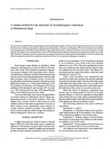
Figure 3: Thrust force measured by dynamometer and observed by force observer during orbital drilling of CFRP/Ti stack using a conventional end mill.
𝐾 (𝑡) = 𝑃 (𝑡) 𝐶𝑇 (𝑡) 𝑅−1 (𝑡) . Theorem 1. Let Γ ∈ 𝑅𝑝×𝑝 be any symmetric positive definite matrix. Under Assumptions 1 and 2, (29) is a global exponential adaptive observer for system (11). That is, for any initial con̂ ) and ∀𝜃 ∈ 𝑅𝑝 , the state estimation ̂ 0 ), and 𝜃(𝑡 ditions 𝑥(𝑡0 ), 𝑥(𝑡 0 ̂ ̂ and parameter estimation error 𝜃(𝑡) − 𝜃(𝑡) error 𝑥(𝑡) − 𝑥(𝑡) exponentially converge to zero [25, 26]. Since the constant matrix Γ significantly affects the antinoise performance and convergence rate of the adaptive observer, which is generally hard to obtain, a time-varying matrix D(𝑡) is utilized to replace the constant matrix Γ according to [27]. D(𝑡) is obtained by the RLS (Recursive Least Squares) algorithm with exponential forgetting factor. Therefore, the adaptive observer (29) can be given by Υ̇ = (𝐴 − 𝐾𝐶) Υ + Ψ, Γ̇ = −ΓΥ𝑇 𝐶𝑇 𝐶ΥΓ + 𝜆Γ, ̂̇ = 𝐴𝑥̂ + 𝐵𝑢 + Ψ𝜃̂ + (𝐾 + ΥΓΥ𝑇 𝐶𝑇 ) (𝑦 − 𝐶𝑥) ̂ , 𝑥
(34)
̇ ̂ , 𝜃̂ = ΓΥ𝑇 𝐶𝑇 (𝑦 − 𝐶𝑥) where 𝜆 > 0 is the forgetting factor and the initial value Γ(0) ∈ 𝑅𝑝×𝑝 can be any symmetric positive definite matrix.
4. Detection of Stack Interface The cutting force signals are recorded during the robotic orbital drilling experiments. Figure 3 shows an example of the recorded signals when feeding the tool into the stack, of which CFRP is the first layer and titanium is the second layer. The graph shows a good correlation between the thrust force measured by dynamometer and that observed by the proposed force observer during the drilling process. The graph also depicts the typical changes in thrust force signal along the tool feed path. There is a sharp rise when the tool enters the
CFRP, and then, the thrust force keeps constant when drilling CFRP layer. A depression (as shown in the enlarged drawing) comes up with the tool transients from the CFRP layer to titanium layer in the case that a slight gap appears between the two layers. But if the layers are in intimate contact with one another, a sharp rise will take place in the transition which performs similarly to the tool entering the CFRP. When the tool has entered the titanium layer, the thrust force shows a slow descending tendency. After that, a rapid decline of the thrust force comes up at the exit of the titanium. The proposed force observer is used to monitor the thrust force during the orbital drilling process. The changes in the shape of the force observations are identified by a moving linear regression algorithm. Monitoring the deviation between the predicted force (calculated by the time-force function defined by linear regression) and observed force at a regular interval makes it practical to detect the tool position in the CFRP/Ti stack. The procedure of the tool position detection is shown as follows, and the flow chart is also presented in Figure 4. (1) The tool position indicator Flag is set to 0 before the tool reaches the workpiece. (2) Force value 𝐹𝑘 measured by cutting force observer is recorded for a regular time interval Δ𝑡. We predict the force 𝐹̂𝑘 of the current time 𝑡𝑘 by the time-force function, 𝐹 = 𝐴 ⋅ 𝑡 + 𝐵, and parameters 𝐴 and 𝐵 are calculated by linear regression with the last 𝑁 force values, 𝐹𝑘−1 , 𝐹𝑘−2 , . . . , 𝐹𝑘−𝑁. The difference 𝐹̃𝑘 between the measured force and predicted force is obtained by 𝐹̃𝑘 = 𝐹𝑘 − 𝐹̂𝑘 . The subscript 𝑘 denotes number of the force value sampled by the detection algorithm. (3) When 𝐹𝑙𝑎𝑔 = 0 and the deviation 𝐹̃𝑘 exceeds the threshold thd 1, it is regarded as the situation in which the tool makes contact with the workpiece, which means the tool is entering the CFRP layer. Then,
6
Mathematical Problems in Engineering
Force observation Flag = 0
Read force data every Δt: Fk Function: F = A · t + B; parameters A and B are calculated by linear regression with the last N force data ̂ k = A · tk + B Predict the force value F ̃ k = Fk − F ̂k Calculate F
Flag = 1
Flag = 0
No ̃ k > thd_1 F
Yes Time_1 = tk Flag = 1
Flag = 2
No
Yes
Yes
Time_2 = tk Flag = 2
Flag = 3
No ̃ k < thd_3 F
̃ k | > thd_2 |F
Time_3 = tk Flag = 3
No
Yes End
Figure 4: Flow chart of the algorithm used for detecting the tool position in CFRP/Ti stack.
the indicator Flag is set to 1 and the time when it happens is recorded as time 1.
respectively, have been identified. Then, the algorithm is ended.
When 𝐹𝑙𝑎𝑔 = 1 and |𝐹̃𝑘 | > 𝑡ℎ𝑑 2, it is regarded as the situation in which the tool is approaching or entering the titanium layer. Then, the indicator Flag is set to 2 and the time when it happens is recorded as time 2.
Considering the safety machining requirement, a fail indicator is assigned if the desired change is not found where it is supposed to be within the time frame of normal process.
When 𝐹𝑙𝑎𝑔 = 2 and the deviation is below thd 3 (thd 3 is a negative value), it is regarded as the situation in which the tool is going to penetrate through the stack. Then, Flag is set to 3 and the time when it happens is recorded as time 3. (4) When the equation, 𝐹𝑙𝑎𝑔 = 3, is satisfied, all the three positions, which denote that the tool enters the CFRP, traverses the material interface, and exits the Ti,
5. Experiments and Results 5.1. Experimental Setup. As shown in Figure 5, experiments were carried out on the Robotic Orbital Drilling System (RHMS) developed at Zhejiang University. The stack plate was mounted on a Kistler 9257B dynamometer which was used to measure the thrust force during the drilling process. The feed drive system employs an AKM 33E servo motor produced by KOLLMORGEN Co., Ltd., and an LC483 absolute linear encoder produced by HEIDENHAIN Co., Ltd., with
Mathematical Problems in Engineering
7 Table 2: Parameters of adaptive observer.
Robot
Symbol 𝑄 𝑅 Γ
Dynamometer
𝜆
Workpiece
End-effector
Figure 5: Experimental setup for robotic orbital drilling.
CFRP Ti
Figure 6: Workpiece sample of CFRP/Ti stacks.
Table 1: Parameters of feed drive system. Symbol 𝐽en 𝐾Tn 𝐾pitch 𝑛
Description Nominal system equivalent inertia Nominal torque constant Pitch of the ball screw Transmission efficiency of the ball screw
Value 0.0003 Kg⋅m2 1.10 Nm/A 0.637 mm/rad 0.95
resolution 5 𝜇m, and the system parameters mentioned in Section 2 are given in Table 1. The CFRP/Ti stack used in the experiment was composed of CFRP and Ti plates. The CFRP plate (T700/QY9611, with a thickness of 5 mm) lay on the top of the titanium plate (Ti6Al-4V, with a thickness of 4.5 mm), and they were bolted together, as shown in Figure 6. The holes with a diameter of 8 mm were orbital drilled with solid carbide end mills featuring four teeth, an overall length of 75 mm, a cutting edge length of 25 mm, and a diameter of 6 mm. All the cutting tests have been carried out at a spindle speed of 2000 rev/min, an orbital speed of 120 rev/min, and a feed rate of 12 mm/min. The tests were carried out in dry machining conditions, since wet conditions can adversely affect the material properties of the composite. The CFRP and titanium chips were evacuated in process via a vacuum dust removal system.
Description Covariance matrix of the system noise Covariance matrix of the measurement noise Symmetric positive definite matrix Forgetting factor
Value diag(0.01, 0.01, 0.01) 0.01 diag(100, 100) 0.5
5.2. Performance of the Cutting Force Observer. The cutting force observer is proposed in Sections 2 and 3, and the parameter value of the adaptive observer is shown in Table 2. The summation of friction force, winding loss, iron loss, and so forth was estimated by the adaptive disturbance observer on the condition of air cutting test with a feed rate of 12 mm/min. It is assumed that the thrust force is equal to zero in the air cutting condition; thus, the output of the motor is regarded as the friction force of the feed drive system in constant feed rate of 12 mm/min. To evaluate the performance of the force observer, the measured force and the observed force of the drilling tests are compared. Figure 7(a) shows the thrust force recorded by the dynamometer when drilling a hole in CFRP/Ti stack that started with the CFRP layer and ended with the titanium layer. Figure 7(b) depicts the comparison of the DC component of the thrust force measured by the dynamometer and that observed by the force observer. Figure 7(c) indicates the relationship between the AC component of the measured force and the ripple force estimated by the adaptive observer, in which the ripple force is obtained by (8). The root mean square (RMS) value of the estimated error, 𝑇 𝜀rms = ((1/𝑇) ∫0 |𝜀|2 𝑑𝑡)1/2 , is used to measure the average observed performance of the cutting force observer, where 𝜀 is the difference between the DC component of the measured force and that of the observed force and 𝑇 represents the cutting time. Average thrust force measured by dynamometer and force observer when drilling CFRP and titanium layers and the average estimate performance of the force observer are presented in Table 3. The estimated errors of the force observer are below 12% and 13% when drilling CFRP and Ti layers, respectively. Although it is not a high accuracy method for the force measurement, basic consistency between the observed force and the true thrust force is guaranteed. In this research, the force observer is aimed at monitoring the thrust force variation when drilling different materials. As shown in Table 3, the thrust force when drilling Ti-alloy is about 3 times higher than that when drilling CFRP in the same drilling operation. Therefore, we consider that estimated errors below 13% are acceptable for the identification of the drilling material. Consequently, we use the cutting force observer for the tool position detection. 5.3. Detection of Tool Position in CFRP/Ti Stack. The developed force observer can measure cutting force in realtime without external sensors. Hence, we consider that
8
Mathematical Problems in Engineering 800
Thrust force (N)
600 400 200 0 0
10
20
30
40
50
60
70
Time (s)
AC component of thrust force (N)
DC component of thrust force (N)
(a)
800 600 400 200 0 0
10
20
30 40 Time (s)
50
60
70
80 60 40 20 0 −20 −40 −60 −80
0
30
40
50
60
70
50
60
70
Dynamometer Force observer 30 Error of DC component (N)
100 Error of DC component (N)
20
Time (s)
Dynamometer Force observer
50 0 −50 −100
10
0
10
20
30 40 Time (s)
50
60
70
(b)
20 10 0 −10 −20 −30
0
10
20
30 40 Time (s) (c)
Figure 7: (a) Thrust force recorded by dynamometer during the drilling test, (b) comparison of the DC component of measured force and thrust force observed by cutting force observer, and (c) comparison of the AC component of measured force and ripple force estimated by adaptive observer (at frequency of 2 Hz, equal to orbital frequency).
the developed feed drive system is able to detect the tool position in orbital drilling process by monitoring the thrust force. In order to verify the effectiveness of the proposed detection algorithm and evaluate the repeatability of this method, 24 holes have been drilled for the position detection tests. The parameters of the detection algorithm mentioned in Section 4 are shown in Table 4. In this experiment, the entering time of CFRP layer, the time of the tool transit of the interface between different materials, and the exit time of Ti layer are identified.
The time nodes identified by the detection algorithm are shown in Figure 8. Table 5 lists the differences between the drilling depth of the cutting tool and the true position of the workpiece. Drilling depth is calculated by the feed rate which multiplies the time given by the detection algorithm. A negative sign indicates that a change of the material being drilled is found ahead of time and position, while a positive value indicates a delay. The accuracy of the identified position of the tool is depicted in Figure 9 clearly. The upper surface of the stack was detected after the tool enters the CFRP
Mathematical Problems in Engineering
9
Table 3: Comparison of measured and observed thrust force when drilling CFRP and Ti layers. Test number 1 2 3 4 5 6 7 8 9 10 11 12 13 14 15 16 17 18 19 20 21 22 23 24
Thrust force when drilling CFRP Measured (N) Observed (N) 𝜀rms (N) Deviation (%) 83.47 85.91 10.27 11.95 99.28 102.19 11.76 11.85 109.13 106.52 11.94 10.94 118.96 116.17 17.20 14.46 129.35 126.10 11.61 8.98 132.88 128.39 11.85 8.92 139.02 139.82 12.79 9.20 152.06 146.17 13.54 8.90 151.38 148.21 12.27 8.11 157.83 157.46 13.66 8.65 149.78 151.66 15.78 10.54 162.59 159.46 11.05 6.80 169.51 161.96 12.72 7.50 168.87 166.10 14.53 8.60 172.47 168.19 16.37 9.49 172.63 162.19 16.22 9.40 180.10 172.47 21.31 11.83 182.53 175.50 16.36 8.96 205.38 196.45 17.20 8.37 196.28 187.14 16.81 8.56 195.24 181.41 21.12 10.82 200.63 190.24 17.80 8.87 196.72 181.05 18.59 9.45 203.80 194.89 19.53 9.58
Measured (N) 277.00 312.23 349.95 378.93 393.47 425.12 442.30 464.38 471.32 489.12 510.27 548.53 542.07 553.20 570.95 589.04 609.20 627.18 495.66 652.28 648.23 679.41 683.71 713.97
Thrust force when drilling Ti Observed (N) 𝜀rms (N) Deviation (%) 259.07 24.01 8.67 298.61 21.06 6.75 317.21 37.21 10.63 343.22 38.24 10.09 362.31 36.16 9.19 401.00 29.84 7.02 412.64 35.36 7.99 429.31 39.47 8.50 414.53 58.46 12.40 455.81 36.67 7.50 457.20 54.58 10.70 511.78 36.62 6.68 482.16 59.99 11.07 499.88 53.58 9.69 526.67 45.13 7.90 535.50 54.23 9.21 548.91 61.43 10.08 576.45 52.51 8.37 453.04 45.37 9.15 597.01 58.32 8.94 595.99 57.13 8.81 630.90 52.20 7.68 635.91 50.34 7.36 651.37 64.55 9.04
Table 4: Parameters of the detection algorithm. 𝑡ℎ𝑑 2 50 N
𝑡ℎ𝑑 3 −30 N
1000
Observed force (N)
800 600 CFRP
400
Ti
200 0 0
10
20
30
40
50
60
70
Feed
𝑡ℎ𝑑 1 50 N
Air Accuracy of identified tool position (mm)
Δ𝑡 0.02 s
0.04 0.06 0.08 0.1
CFRP
−0.1 −0.05 0 0.05 0.1
Ti
−1 −0.5 0
Time (s) Observed force CFRP entering time
Interface transit time Ti exit time
Figure 8: Time nodes identified by the detection algorithm with observed force.
layer within 0.5 s; the position accuracy is below 0.1 mm. The accuracy of the interface position between different materials
Air 0
5
10 15 Test number
20
25
CFRP entering Interface transit Ti exit
Figure 9: Accuracy of the identified tool position when the tool enters CFRP, transits the material interface, and exits Ti.
10
Mathematical Problems in Engineering Table 5: Differences in time and feed depth between the values identified by the detection algorithm and the measured value.
Test number 1 2 3 4 5 6 7 8 9 10 11 12 13 14 15 16 17 18 19 20 21 22 23 24
ΔCFRP entering Drilling time (s) Drilling depth (mm) 0.417 0.083 0.269 0.054 0.325 0.065 0.290 0.058 0.305 0.061 0.260 0.052 0.310 0.062 0.290 0.058 0.260 0.052 0.267 0.053 0.450 0.090 0.260 0.052 0.310 0.062 0.320 0.064 0.290 0.058 0.300 0.060 0.470 0.094 0.252 0.050 0.260 0.052 0.470 0.094 0.230 0.046 0.226 0.045 0.340 0.068 0.300 0.060
Δinterface transit Drilling time (s) Drilling depth (mm) 0.196 0.039 −0.115 −0.023 0.092 0.018 −0.234 −0.047 0.162 0.032 0.230 0.046 0.148 0.030 −0.032 −0.006 −0.123 −0.025 −0.165 −0.033 0.366 0.073 −0.092 −0.018 −0.121 −0.024 −0.123 −0.025 −0.160 −0.032 −0.162 −0.032 −0.130 −0.026 −0.063 −0.013 −0.100 −0.020 0.072 0.014 −0.072 −0.014 −0.026 −0.005 0.074 0.015 −0.070 −0.014
was detected in the range of −0.05∼0.05 mm, which means that the interface could be detected 0.25 s before or after the tool penetrates it. But a much poorer accuracy of tool position, when the tool exited the stack, was obtained. The difficulty lied in accurately detecting the time when the tool exited the titanium layer, which is mainly affected by the complicated deformation of the uncut titanium plate. The interaction between the thrust force and the decreasing depth of the uncut material leads to the value of the thrust force becoming fuzzy. In the study of Neugebauer et al. [14], the stack interface is detected within 0.8 mm (0.17 s) when drilling from CFRP to Al using standard drill. From the above experimental results, it is clear that our proposed force sensorless method has performance comparable to the acoustic emission based method.
ΔTi exit Drilling time (s) Drilling depth (mm) −4.970 −0.994 −0.150 −0.030 −2.236 −0.447 −0.021 −0.004 −0.383 −0.077 −4.621 −0.924 −1.657 −0.331 −0.853 −0.171 −1.110 −0.222 −1.512 −0.302 −1.155 −0.231 −4.430 −0.886 −3.760 −0.752 −3.380 −0.676 −0.660 −0.132 −3.320 −0.664 −5.340 −1.068 −4.780 −0.956 −0.270 −0.054 −2.330 −0.466 −1.860 −0.372 −1.999 −0.400 −1.400 −0.280 −6.010 −1.202
speed, orbital speed, and feed rate to adapt the materials being drilled during the drilling operation. Hence, the quality of the hole and the cutting tool life can be improved. Since the thrust force is used as the indicator of the tool position in the stack, the disparity in hardness of different materials will be remarkable. Otherwise, it may be difficult to detect the stack interface by monitoring the thrust force. The suitable thresholds affect the identification accuracy of the tool position, which should be further optimized. In order to enhance the accuracy of the force observer which is affected by the cogging force of the motor, ripple force of the ball screw, and friction of the guide rail, a better machine structure should be developed, for example, using direct drive motor instead of the rotary motor and ball screw and using air-slider instead of the guide rail.
Conflict of Interests 6. Conclusion It is shown that the thrust force observed by the developed force observer can provide a good solution for monitoring the drill position in the CFRP/Ti stack. The point where the cutting tool enters into the stack, exits from the stack, and transits the interface of different materials can be identified during the drilling process of the CFRP/Ti stack. As a result, it is possible to change the drilling parameters such as spindle
The authors declare that there is no conflict of interests regarding the publication of this paper.
Acknowledgment The authors would like to gratefully acknowledge the Fundamental Research Funds for the Central Universities (no. 2015FZA4005) for providing financial support to this work.
Mathematical Problems in Engineering
References [1] D. Kim and M. Ramulu, “Drilling process optimization for graphite/bismaleimide-titanium alloy stacks,” Composite Structures, vol. 63, no. 1, pp. 101–114, 2004. [2] M. Ramulu, T. Branson, and D. Kim, “A study on the drilling of composite and titanium stacks,” Composite Structures, vol. 54, no. 1, pp. 67–77, 2001. [3] D. Che, I. Saxena, P. Han, P. Guo, and K. F. Ehmann, “Machining of carbon fiber reinforced plastics/polymers: a literature review,” Journal of Manufacturing Science and Engineering, vol. 136, no. 3, Article ID 034001, 22 pages, 2014. [4] D. Liu, Y. Tang, and W. L. Cong, “A review of mechanical drilling for composite laminates,” Composite Structures, vol. 94, no. 4, pp. 1265–1279, 2012. [5] E. O. Ezugwu and Z. M. Wang, “Titanium alloys and their machinability—a review,” Journal of Materials Processing Technology, vol. 68, no. 3, pp. 262–274, 1997. [6] P. F. Zhang, N. J. Churi, Z. J. Pei, and C. Treadwell, “Mechanical drilling processes for titanium alloys: a literature review,” Machining Science and Technology, vol. 12, no. 4, pp. 417–444, 2008. [7] I. S. Shyha, D. K. Aspinwall, S. L. Soo, and S. Bradley, “Drill geometry and operating effects when cutting small diameter holes in CFRP,” International Journal of Machine Tools and Manufacture, vol. 49, no. 12-13, pp. 1008–1014, 2009. [8] I. S. Shyha, S. L. Soo, D. K. Aspinwall et al., “Hole quality assessment following drilling of metallic-composite stacks,” International Journal of Machine Tools and Manufacture, vol. 51, no. 7-8, pp. 569–578, 2011. [9] X. Wang, P. Y. Kwon, C. Sturtevant, D. D.-W. Kim, and J. Lantrip, “Comparative tool wear study based on drilling experiments on CFRp/Ti stack and its individual layers,” Wear, vol. 317, no. 1-2, pp. 265–276, 2014. [10] E. Brinksmeier and R. Janssen, “Drilling of multi-layer composite materials consisting of carbon fiber reinforced plastics (CFRP), titanium and aluminum alloys,” CIRP Annals— Manufacturing Technology, vol. 51, no. 1, pp. 87–90, 2002. [11] R. Zitoune, V. Krishnaraj, and F. Collombet, “Study of drilling of composite material and aluminium stack,” Composite Structures, vol. 92, no. 5, pp. 1246–1255, 2010. [12] V. Krishnaraj, A. Prabukarthi, M. Santhosh, M. Senthilkumar, and R. Zitoune, “Optimization of machining parameters in CFRP/Ti stacks drilling,” in Proceedings of the ASME International Manufacturing Science and Engineering Conference, Paper no. MSEC2012-7216, pp. 269–275, Notre Dame, Ind, USA, June 2012. [13] K.-H. Park, A. Beal, D. D.-W. Kim, P. Kwon, and J. Lantrip, “Tool wear in drilling of composite/titanium stacks using carbide and polycrystalline diamond tools,” Wear, vol. 271, no. 11-12, pp. 2826–2835, 2011. [14] R. Neugebauer, U. Ben-Hanan, S. Ihlenfeldt, M. Wabner, and A. Stoll, “Acoustic emission as a tool for identifying drill position in fiber-reinforced plastic and aluminum stacks,” International Journal of Machine Tools and Manufacture, vol. 57, pp. 20–26, 2012. [15] C. H. Lauro, L. C. Brand˜ao, D. Baldo, R. A. Reis, and J. P. Davim, “Monitoring and processing signal applied in machining processes—a review,” Measurement, vol. 58, pp. 73–86, 2014. [16] R. Teti, K. Jemielniak, G. O’Donnell, and D. Dornfeld, “Advanced monitoring of machining operations,” CIRP Annals— Manufacturing Technology, vol. 59, no. 2, pp. 717–739, 2010.
11 [17] T.-Y. Kim, J. Woo, D. Shin, and J. Kim, “Indirect cutting force measurement in multi-axis simultaneous NC milling processes,” International Journal of Machine Tools and Manufacture, vol. 39, no. 11, pp. 1717–1731, 1999. [18] M. D¨olen, B. Kaftanoglu, and R. D. Lorenz, “A cutting force estimator for CNC machining centers,” CIRP Annals—Manufacturing Technology, vol. 53, no. 1, pp. 313–316, 2004. [19] S. T¨onissen, R. Koike, Y. Kakinuma, T. Aoyama, and F. Klocke, “Monitoring of tool collision in drilling by disturbance observer,” CIRP Journal of Manufacturing Science and Technology, vol. 7, no. 3, pp. 274–282, 2014. [20] Y. Kakinuma and T. Kamigochi, “External sensor-less tool contact detection by cutting force observer,” Procedia CIRP, vol. 2, pp. 44–48, 2012. [21] X. Li, A. Djordjevich, and P. K. Venuvinod, “Current-sensorbased feed cutting force intelligent estimation and tool wear condition monitoring,” IEEE Transactions on Industrial Electronics, vol. 47, no. 3, pp. 697–702, 2000. [22] S. N. Huang, K. K. Tan, Y. S. Wong, C. W. de Silva, H. L. Goh, and W. W. Tan, “Tool wear detection and fault diagnosis based on cutting force monitoring,” International Journal of Machine Tools and Manufacture, vol. 47, no. 3-4, pp. 444–451, 2007. [23] T. Yoneoka, Y. Kakinuma, K. Ohnishi, and T. Aoyama, “Disturbance observer-based in-process detection and suppression of chatter vibration,” Procedia CIRP, vol. 1, pp. 44–49, 2012. [24] H. Kihlman, I. Eriksson, and M. Ennis, “Robotic orbital drilling of structures for aerospace applications,” SAE Technical Paper 2002-01-2636, SAE International, Warrendale, Pa, USA, 2002. [25] Q. Zhang, “Adaptive observer for multiple-input-multipleoutput (MIMO) linear time-varying systems,” IEEE Transactions on Automatic Control, vol. 47, no. 3, pp. 525–529, 2002. [26] A. Xu and Q. Zhang, Global Adaptive Observer for a Class of Nonlinear Systems, 2001, https://hal.inria.fr/inria-00072341/ document. [27] Q. Zhang and A. Clavel, “Adaptive observer with exponential forgetting factor for linear time varying systems,” in Proceedings of the 40th IEEE Conference on Decision and Control (CDC ’01), vol. 4, pp. 3886–3891, December 2001.
Advances in
Operations Research Hindawi Publishing Corporation http://www.hindawi.com
Volume 2014
Advances in
Decision Sciences Hindawi Publishing Corporation http://www.hindawi.com
Volume 2014
Journal of
Applied Mathematics
Algebra
Hindawi Publishing Corporation http://www.hindawi.com
Hindawi Publishing Corporation http://www.hindawi.com
Volume 2014
Journal of
Probability and Statistics Volume 2014
The Scientific World Journal Hindawi Publishing Corporation http://www.hindawi.com
Hindawi Publishing Corporation http://www.hindawi.com
Volume 2014
International Journal of
Differential Equations Hindawi Publishing Corporation http://www.hindawi.com
Volume 2014
Volume 2014
Submit your manuscripts at http://www.hindawi.com International Journal of
Advances in
Combinatorics Hindawi Publishing Corporation http://www.hindawi.com
Mathematical Physics Hindawi Publishing Corporation http://www.hindawi.com
Volume 2014
Journal of
Complex Analysis Hindawi Publishing Corporation http://www.hindawi.com
Volume 2014
International Journal of Mathematics and Mathematical Sciences
Mathematical Problems in Engineering
Journal of
Mathematics Hindawi Publishing Corporation http://www.hindawi.com
Volume 2014
Hindawi Publishing Corporation http://www.hindawi.com
Volume 2014
Volume 2014
Hindawi Publishing Corporation http://www.hindawi.com
Volume 2014
Discrete Mathematics
Journal of
Volume 2014
Hindawi Publishing Corporation http://www.hindawi.com
Discrete Dynamics in Nature and Society
Journal of
Function Spaces Hindawi Publishing Corporation http://www.hindawi.com
Abstract and Applied Analysis
Volume 2014
Hindawi Publishing Corporation http://www.hindawi.com
Volume 2014
Hindawi Publishing Corporation http://www.hindawi.com
Volume 2014
International Journal of
Journal of
Stochastic Analysis
Optimization
Hindawi Publishing Corporation http://www.hindawi.com
Hindawi Publishing Corporation http://www.hindawi.com
Volume 2014
Volume 2014