Alessandro Rossini, Khalid A. Mughal, Uwe Wolter. Department of ... In addition,
constraints specified at model level are mapped to Java annotations which are.
Replace this file with prentcsmacro.sty for your meeting, or with entcsmacro.sty for your meeting. Both can be found at the ENTCS Macro Home Page.
A Formal Approach to Data Validation Constraints in MDE Alessandro Rossini, Khalid A. Mughal, Uwe Wolter Department of Informatics University of Bergen Bergen, Norway
Adrian Rutle, Yngve Lamo Department of Computer Engineering Bergen University College Bergen, Norway
Abstract Software security encompasses the measures taken to ensure confidentiality, integrity and availability in software systems. In present-day software development, security is often an afterthought rather than part of the software development life-cycle. In order to reveal potential security flaws before a software system is actually implemented, security aspects should be taken into account starting from the early phases of the development. With model-driven engineering (MDE) gaining momentum in both academia and industry, an interesting challenge is the specification of security constraints within software models. In this paper we focus on data validation – the process of ensuring that a system operates on correct and meaningful data – in the context of MDE. Our contribution is a formal approach to the specification of data validation constraints which involve multiple structural properties. In addition, constraints specified at model level are mapped to Java annotations which are then transformed to executable tests by an existing data validation framework. Keywords: data validation; model-driven engineering; category theory; Diagram Predicate Framework; SHIP Validator
1 Introduction Software systems are nowadays widespread in all walks of society. Violating the confidentiality, integrity and availability of these systems can therefore lead to a negative impact on the economy and health. Software security aims at ensuring that these properties are not compromised. In present-day software development, security is often neglected because of lack of skills and budget, and time-to-market c 2011 Published by Elsevier Science B. V.
Rossini et al.
constraints. Typically, security concerns are considered far too late when the system is already nearing deployment. This is clearly insufficient since security aspects should be taken into account starting from the early phases of the development [8,11] in order to reveal potential security flaws before a software system is actually implemented. Model-driven engineering (MDE) is a branch of software engineering which aims at improving productivity, quality, and cost-effectiveness of software by shifting the paradigm from code-centric to model-centric. MDE promotes models and modelling languages as the main artefacts of the development process and model transformation as the primary technique to generate (parts of) software systems out of models. Models enable developers to reason at a higher level of abstraction while model transformation alleviates developers from repetitive and error-prone tasks such as coding. In this regard, an interesting challenge is the specification of security constraints within models. In this paper we focus on data validation – the process of ensuring that a system operates on correct and meaningful data – in the context of MDE. The lack of proper data validation is listed as the most prevalent cause of software vulnerabilities by the OWASP [14]. In the state-of-the-art of MDE, models are typically specified by means of modelling languages such as the Unified Modeling Language (UML) [13]. These modelling languages are diagrammatic and allow for the specification of constraints on single structural properties, e.g., a data validation constraint on a single input field. However, the specification of complex constraints on multiple structural properties, e.g., data validation constraint on multiple input fields, requires textual constraint languages such as the Object Constraint Language (OCL) [12]. It is the authors’ experience that a completely diagrammatic approach to the specification of data validation constraints in MDE would be desirable [17]. The contribution of this paper is a formal approach to the specification of data validation constraints which can involve multiple, interdependent structural properties. The underpinning of the proposed approach is the Diagram Predicate Framework (DPF) [15,16,17,18] which provides a formalisation of (meta)modelling and model transformation based category theory [1] and graph transformation [5]. The paper also shows how data validation constraints specified at model level are mapped to Java annotations. These annotations are in turn transformed to executable tests at run-time by the SHIP Validator [7,10], a Java based framework which enables the validation of multiple interdependent properties of Java objects. The remainder of the paper is structured as follows. Section 2 presents DPF. Section 3 introduces the formal approach to data validation by means of a running example. In Section 4, the current research in security within MDE is summarised. Finally, in Section 5, some concluding remarks and ideas for future work are outlined. 2
Rossini et al.
2 Diagram Predicate Framework Before introducing DPF, the terminology adopted in this paper is clarified. The term model has different meanings in different contexts. In software engineering, a model denotes “an abstraction of a (real or language-based) system allowing predictions or inferences to be made” [9]. Models in software engineering are typically diagrammatic. The term diagram has also different meanings in different contexts. In software engineering, a diagram denotes a structure which is based on graphs, i.e., a collection of nodes together with a collection of arrows between nodes. Graphs are a well-known and well-understood means to represent structural and behavioural properties of a software system [5], e.g., Entity-Relationship (ER) diagrams and UML diagrams [13]. Since graph-based structures are often visualised in a natural way, the terms diagrammatic and visual and are often treated as synonyms. In this paper, however, visualisation and diagrammatic syntax are clearly distinguished; i.e., this work focuses on syntax and semantics of diagrammatic models independent of their visualisation. In DPF, a model is represented by a specification S. A specification S = (S, C S : Σ) consists of an underlying graph S together with a set of atomic constraints C S which are specified by a signature Σ. A signature Σ = (ΠΣ , αΣ ) consists of a collection of predicates π ∈ ΠΣ , each having an arity (or shape graph) αΣ (π), a proposed visualisation and a semantic interpretation. An atomic constraint (π, δ) consists of a predicate π ∈ ΠΣ together with a graph homomorphism δ : αΣ (π) → S from the arity of the predicate to the underlying graph of the specification. Definition 2.1 [Signature] A signature Σ = (ΠΣ , αΣ ) consists of a collection of predicate symbols ΠΣ and a map αΣ which assigns a graph to each predicate symbol π ∈ ΠΣ . αΣ (π) is called the arity of the predicate symbol π. Definition 2.2 [Atomic constraint] Given a signature Σ = (ΠΣ , αΣ ), an atomic constraint (π, δ) on a graph S consists of a predicate symbol π ∈ ΠΣ and a graph homomorphism δ : αΣ (π) → S. Definition 2.3 [Specification] Given a signature Σ = (ΠΣ , αΣ ), a specification S = (S, C S : Σ) consists of a graph S and a set C S of atomic constraints (π, δ) on S with π ∈ ΠΣ . The semantics of nodes and arrows of the underlying graph of a specification has to be chosen in a way which is appropriate for the corresponding modelling environment [17]. In object-oriented structural modelling, each object may be related to a set of other objects. Hence, it is appropriate to interpret nodes as sets and f arrows X − → Y as multi-valued functions f : X → ℘(Y ). The powerset ℘(Y ) of Y 3
Rossini et al.
is the set of all subsets of Y , i.e., ℘(Y ) = {A | A ⊆ Y }. Moreover, the composition of two multi-valued functions f : X → ℘(Y ), g : Y → ℘(Z) is defined by S (f ; g)(x) := {g(y) | y ∈ f (x)}. Example 2.4 [Signature and specification] Let us consider an information system for the management of students and universities. The information system has the following requirements: (i) A student studies at one to four universities. (ii) A university educates none to many students. Table 1 shows a signature Σ = (ΠΣ , αΣ ) which is suitable for object-oriented structural modelling. Table 1 A signature Σ = (ΠΣ , αΣ )
π
αΣ (π)
[mult(m, n)]
1
a
2
X
[injective]
1
a
2
X
f [inj]
Y
∀x, x′ ∈ X : f (x) = f (x′ ) implies x = x′
[surjective]
1
a
2
X
f [surj]
Y
∀y ∈ Y ∃x ∈ X : y ∈ f (x)
[inverse]
1
2
X [inv] g
Y
∀x ∈ X , ∀y ∈ Y : y ∈ f (x) iff x ∈ g(y)
Proposed vis. Semantic interpretation f Y [m..n]
f
a
b
Student
∀x ∈ X : m ≤ |f (x)| ≤ n, with 0 ≤ m ≤ n and n ≥ 1
sUnivs [1..4] University [inv] [surj] uStuds
Student
sUnivs
University
uStuds
(a) S
(b) S
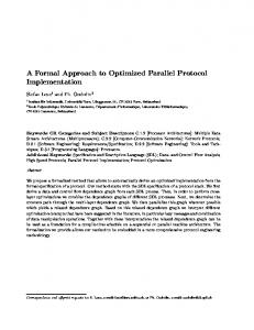
Figure 1. A specification S = (S, C S : Σ) and its underlying graph S
Fig. 1(a) shows a specification S = (S, C S : Σ) which is compliant with the requirements above. Fig. 1(b) shows the underlying graph S of S, i.e., the graph of S without any atomic constraints. In S, the nodes Student and University are interpreted as sets Student and University, and the arrows sUnivs and uStuds are interpreted as multi-valued functions sUnivs : Student → ℘(University) and uStuds : University → ℘(Student), respectively. 4
Rossini et al.
Based on the requirement i, the function sUnivs has cardinality between one and four. This is enforced by the atomic constraint ([mult(1, 4)], δ1 ) on the arrow sUnivs. Moreover, the function uStuds is surjective. This is enforced by the atomic constraint ([surjective], δ3 ) on the arrow uStuds. Finally, the functions sUnivs and uStuds are inverse of each other, i.e., ∀s ∈ Student and ∀u ∈ University : s ∈ uStuds(u) iff u ∈ sUnivs(s). This is enforced by the atomic constraint ([inverse], δ2 ) on sUnivs and uStuds. The graph homomorphisms δ1 , δ2 and δ3 are defined as follows (see Table 2): δ1 (1) = Student,
δ1 (2) = University,
δ1 (a) = sUnivs
δ2 (1) = Student,
δ2 (2) = University,
δ2 (a) = sUnivs, δ2 (b) = uStuds
δ3 (1) = University, δ3 (2) = Student,
δ3 (a) = uStuds
Table 2 The atomic constraints (π, δ) ∈ C S and their graph homomorphisms (π, δ) ([mult(1, 4)], δ1 )
αΣ (π) 1
a
δ(αΣ (π))
2
Student
1
2
1
a
University
Student
b
([surjective], δ3 )
University
sUnivs
a
([inverse], δ2 )
sUnivs
uStuds
University
2
uStuds
Student
Remark 2.5 [Predicate symbols] Some of the predicate symbols in Σ (see Table 1) refer to single predicates, e.g., [surjective], while some others refer to a family of predicates, e.g., [mult(m, n)]. In the case of [mult(m, n)], the predicate is parametrised by the (non-negative) integers m and n, which represent the lower and upper bounds, respectively, of the cardinality of the function which is constrained by this predicate. The semantics of predicates of the signature Σ (see Table 1) is described using the mathematical language of set theory. In an implementation, the semantics of a predicate is typically given by the code of a corresponding validator where both the mathematical and the validator semantics should coincide. However, it is not necessary to choose between the above mentioned possibilities; it is sufficient to know that any of these possibilities defines valid instances of predicates. Definition 2.6 [Semantics of predicates] Given a signature Σ = (ΠΣ , αΣ ), a semantic interpretation [[..]]Σ of Σ consists of a mapping that assigns to each predicate symbol π ∈ ΠΣ a set [[π]]Σ of graph homomorphisms ι : O → αΣ (π), called valid instances of π, where O may vary over all graphs. [[π]]Σ is assumed to be closed under isomorphisms. The semantics of a specification is defined in the so-called fibred way [4,20]; i.e., the semantics of a specification is given by the set of its instances. An instance 5
Rossini et al.
(I, ι) of a specification S consists of a graph I together with a graph homomorphism ι : I → S which satisfies the set of atomic constraints C S . To check that an atomic constraint is satisfied in a given instance of a specification S, it is enough to inspect only the part of S which is affected by the atomic constraint. This kind of restriction to a subpart is obtained by the pullback construction [1], which can be regarded as a generalisation of the inverse image construction. Definition 2.7 [Instance of specification] Given a specification S = (S, C S : Σ), an instance (I, ι) of S consists of a graph I and a graph homomorphism ι : I → S such that for each atomic constraint (π, δ) ∈ C S we have ι ∗ ∈ [[π]]Σ , where the graph homomorphism ι ∗ : O ∗ → αΣ (π) is given by the following pullback: δ
αΣ (π) ι∗
O∗
P.B. δ∗
S ι
I
3 Data Validation A running example based on [7,10] is adopted to show how the formal approach to (meta)modelling can be applied to the problem of data validation. Note that the example is kept intentionally simple, retaining only the details which are relevant for the discussion. Example 3.1 [International money transfers] Let us consider international money transfers. IBAN (International Bank Account Number) is the standard for identifying bank accounts internationally. Some countries have not adopted this standard and, for money transfer to these countries, a special clearing code is needed in combination with the plain account number. BIC (Bank Identifier Code) is the standard for identifying banks globally. Therefore, a form for international money transfers should contain (at least) the input fields bic, iban, account and clearingCode. Moreover, supposing that the currency is Euro, the form should also contain the input fields amountEuros and amountCents. In addition, the transfer system should satisfy the following requirements: (i) The BIC code of the beneficiary’s bank is required. (ii) Either the IBAN or both clearing code and account number are required. (iii) The amount to transfer must be between 0.01 and 100000.00 Euros. Table 3 shows a signature Φ = (ΠΦ , αΦ ) which contains predicates used to specify data validation constraints. Note that in the semantic interpretation of the [cross-range] predicate we denote lexicographical order by ≤. 6
Rossini et al. Table 3 The data validation signature Φ π
αΦ (π)
Proposed vis. f
[required]
1
a
[exactly-onenull]
1
a
2
X
2
X
•
b g
f
Semantic interpretation Y
∀x ∈ X : f (x) defined
Y
∀x ∈ X : (f (x) defined and g(x) undefined) or (f (x) undefined and g(x) defined)
Y
∀x ∈ X : (f (x) defined and g(x) defined) or (f (x) undefined and g(x) undefined)
Int
∀x ∈ X : (m1 , n1 ) (f (x), g(x)) ≤ (m2 , n2 )
Int
∀x ∈ X : m ≤ f (x) ≤ n
[eon]
3 Z 1
[all-or-nonenull]
a
2
f
X
b g
[aonn]
3 Z f
a
[cross-range((m1 , n1 ), (m2 , n2 ))]
1
[range(m, n)]
1
2
X
[m1 .n1 −m2 .n2 ]
b a
g
2
f [m−n]
X
≤
bic iban
Payment
account
[eon]
clearingCode
[aonn]
bic iban
String Payment
String
amountEuros
amountCents
[0.01-100000.00]
amountEuros
amountCents [0-99]
account clearingCode
Integer
Integer (a) P
(b) P
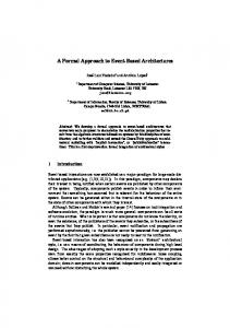
Figure 2. The specification P = (P, C P : Φ) and its underlying graph P
Fig. 2(a) shows a specification P = (P, C P : Φ) which is compliant with the requirements above. The form is represented by the node Payment while the input fields are represented by the arrows bic, iban, account, clearingCode, amountEuros and amountCents. Fig. 2(b) presents the underlying graph P of P, i.e., the graph of P without any atomic constraints. In P, the requirement i is enforced by the atomic constraint ([required], a bic δ1 ) on the arrow bic, i.e., δ1 : (1 − → 2) 7→ (Payment −→ String). This atomic constraint ensures that the user provides a value in the input field bic. Moreover, the requirement ii is enforced in P by two atomic constraints: ([exactly-one-null], 7
Rossini et al.
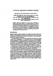
δ2 ) on the arrows iban and account together with ([all-or-none-null], δ3 ) on the arrows account and clearingCode. These atomic constraints ensure that a user provides values in either the input field iban or both the input fields account and clearingCode. Furthermore, the requirement iii is enforced in P by the atomic constraint ([cross-range((0, 1), (100000, 0))], δ4 ) on the arrows amountEuros and amountCents. This atomic constraint ensures that the user provides values in the input fields amountEuros and amountCents which sum up to a value within the range 0.01 to 100000.00. In addition, the atomic constraint ([range(0, 99)], δ5 ) on the arrow amountCents ensures that a user provides a value in the input field amountCents within the range 0 to 99. Fig. 3(b) shows a valid instance I of the specification P = (P, C P : Φ). Fig. 3 also shows the mappings of the graph homomorphism ι : I → P as dashed, grey arrows. bic iban
Payment
account
[eon]
clearingCode
[aonn]
DNBANOKKXXX
String 1
NO4970019999999
[0.01-100000.00]
amountEuros
amountCents [0-99]
50 100 Integer (a) P
(b) I
Figure 3. The specification P = (P, C P : Φ) and a possible instance I
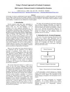
As mentioned, in an implementation, the semantics of a predicate is typically given by the code of a corresponding validator where both the mathematical and the validator semantics should coincide. In this paper, we have chosen to base the implementation of each predicate on the SHIP Validator [7,10]. The XMI serialisation (see Listing 1) of the specification P = (P, C P : Φ) specifying the form in Example 3.1 can be transformed to a Java class (see Listing 2) tagged by Java annotations compatible with the SHIP Validator. For each atomic constraint (π, δ) ∈ C P a corresponding Java annotation is attached to the getter methods of the Java class. Note that an atomic constraint on a single arrow, e.g., ([required], δ1 ) on the arrow bic, translates to a single Java annotation, e.g., @Required on the method getBic(). Likewise, an atomic constraint on multiple arrows, e.g., ([exactly-one-null], δ2 ) on the arrows iban and account, translates to multiple Java annotations, e.g., @ExactlyOneNull on the methods getIban() and getAccount(). The interested reader can download a proof-of-concept implementation of a code generator from [2]. 8
Rossini et al.
Listing 1: XMI serialisation of the specification P = (P, C P: Φ) 1 2 3 4 5 6 7 8 9 10 11 12 13 14 15 16 17 18 19 20 21 22 23 24 25 26 27 28 29 30 31 32 33 34 35 36 37 38 39 40 41 42 43 44 45 46 47 48 49 50 51 52 53 54
name="bic" source="//@node.0" name="iban" source="//@node.0" name="account" source="//@node name="clearingCode" source="// name="amountEuros" source="// name="amountCents" source="//
9
Rossini et al.
Listing 2: Java class generated by transformation 1 2 3 4 5 6 7 8 9 10 11 12 13 14 15 16 17 18 19 20 21 22 23 24 25 26 27 28 29 30 31 32 33 34 35 36 37 38 39 40 41 42 43 44 45 46 47
public class Payment { private private private private
String String String String
bic; iban; account; clearingCode;
private int amountEuros; private int amountCents; @Required public String getBic() { return bic; } @ExactlyOneNull @NotRequired public String getIban() { return iban; } @ExactlyOneNull @AllOrNoneNull @NotRequired public String getAccount() { return account; } @AllOrNoneNull @NotRequired public String getClearingCode() { return clearingCode; } @IntRange(min=0,max=100000) @CrossRange public int getAmountEuros(){ return this.amountEuros; } @IntRange(min=0,max=99) @CrossRange public int getAmountCents(){ return this.amountCents; } }
These Java annotations are in turn transformed into executable tests by the SHIP Validator. The interested reader can consult [7,10] for details about the implementation and execution of these tests. Note that the idea of using annotations to hide the actual validation code and, at the same time, tag the properties to be tested, allow the constraints to be easily integrated into existing code. Besides, the validation aspects of the system remain well separated from the application aspects. This separation of concerns facilitates the transformation of the diagrammatic constraints into actual existing working code.
10
Rossini et al.
4 Related Work In [6], an approach to integrate input validation constraints into UML diagrams using OCL is presented. In particular, this approach targets four different UML diagrams, i.e., use case diagram, class diagram, sequence diagram and activity diagram. This solution enables the specification of input validation constraints on behavioural models while our approach targets structural models only. However, it adopts a textual constraint language such as OCL while our approach is completely diagrammatic. In [8], the author illustrates an approach to enrich UML models with security requirements such as secrecy, integrity and authenticity. The approach exploits UML extension mechanisms such as keywords, tags and constraints. In particular, keywords are used together with tags to specify security requirements on the system, while constraints give criteria to determine if these requirements are satisfied by the UML model. However, keywords and tags can be attached only to single model elements, thus these mechanism are not sufficient to express data validation constraints involving multiple structural properties at the model level. On the contrary, data validation constraints involving multiple structural properties can be expressed in our approach in a diagrammatic fashion.
5 Conclusion and Future Work In this paper, we have illustrated some of the key aspects of data validation in MDE. We have adopted DPF to define an approach to the specification of data validation constraints in models. Moreover, we have shown how these constraints can be mapped to Java annotations which are transformed to executable tests. The diagrammatic and formal nature of the proposed approach constitutes the main contribution and novelty of this work. In a future work, we will introduce a reasoning system for the analysis of predicate dependencies and a logic for this analysis. This extension will enable users of the proposed approach to detect possible inconsistencies between data validation constraints. Moreover, we will integrate the code generator, which transforms the constraints at model level to Java annotations, in the DPF Editor [3], a diagrammatic (meta)modelling tool based on DPF and Eclipse Modeling Framework (EMF) [19]. Acknowledgement The authors would like to thank Øyvind Bech and Dag Viggo Lokøen for the proofof-concept implementation of the code generator, and Federico Mancini for the support with the SHIP Validator.
11
Rossini et al.
References [1] Barr, M. and C. Wells, “Category Theory for Computing Science (2nd Edition),” Prentice Hall, 1995. [2] Bech, Ø. and D. V. Lokøen, “DPF to SHIP Validator Proof-of-Concept Transformation Engine,” http://dpf.hib.no/code/transformation/dpf_to_shipvalidator.py. [3] Bergen University College and University of Bergen, “Diagram Predicate Framework Web Site,” http://dpf.hib.no/. [4] Diskin, Z. and U. Wolter, A Diagrammatic Logic for Object-Oriented Visual Modeling, in: Proceedings of ACCAT 2007: 2nd Workshop on Applied and Computational Category Theory, Electronic Notes in Theoretical Computer Science 203/6 (2008), pp. 19–41. [5] Ehrig, H., K. Ehrig, U. Prange and G. Taentzer, “Fundamentals of Algebraic Graph Transformation,” Springer, 2006. [6] Hayati, P., N. Jafari, S. M. Rezaei, S. Sarencheh and V. Potdar, Modeling Input Validation in UML, in: Proceedings of ASWEC 2008: 19th Australian Software Engineering Conference (2008), pp. 663–672. [7] Hovland, D., F. Mancini and K. Mughal, The SHIP Validator: An Annotation-Based Content-Validation Framework for Java Applications, Technical Report 389, Department of Informatics, University of Bergen, Norway (2009). [8] Jürjens, J., “Secure Systems Development with UML,” Springer, 2005. [9] Kühne, T., Matters of (meta-)modeling, Software and Systems Modeling 5 (2006), pp. 369–385. [10] Mancini, F., D. Hovland and K. Mughal, Investigating the Limitations of Java Annotations for Input Validation, in: Proceedings of ARES 2010: 5th International Conference on Availability, Reliability and Security (2010). [11] McGraw, G., “Software Security: Building Security in,” Addison-Wesley Professional, 2006. [12] Object Management Group, “Object Constraint http://www.omg.org/spec/OCL/2.2/.
Language
Specification,”
(2010),
[13] Object Management Group, “Unified http://www.omg.org/spec/UML/2.3/.
Language
Specification,”
(2010),
Modeling
[14] OWASP, “Top Ten Project,” http://www.owasp.org. [15] Rossini, A., A. Rutle, Y. Lamo and U. Wolter, A formalisation of the copy-modify-merge approach to version control in MDE, Journal of Logic and Algebraic Programming 79 (2010), pp. 636–658. [16] Rutle, A., “Diagram Predicate Framework: A Formal Approach to MDE,” Ph.D. thesis, Department of Informatics, University of Bergen, Norway (2010). [17] Rutle, A., A. Rossini, Y. Lamo and U. Wolter, A Diagrammatic Formalisation of MOF-Based Modelling Languages, in: M. Oriol, B. Meyer, W. Aalst, J. Mylopoulos, M. Rosemann, M. Shaw and C. Szyperski, editors, Proceedings of TOOLS 2009: 47th International Conference on Objects, Components, Models and Patterns, Lecture Notes in Business Information Processing 33 (2009), pp. 37–56. [18] Rutle, A., A. Rossini, Y. Lamo and U. Wolter, A formal approach to the specification and transformation of constraints in MDE, Journal of Logic and Algebraic Programming (To appear). [19] Steinberg, D., F. Budinsky, M. Paternostro and E. Merks, “EMF: Eclipse Modeling Framework 2.0 (2nd Edition),” Addison-Wesley Professional, 2008. [20] Wolter, U. and Z. Diskin, From Indexed to Fibred Semantics – The Generalized Sketch File, Technical Report 361, Department of Informatics, University of Bergen, Norway (2007).
12