, P = P = {p , p }, I = {i , i e1 1 e2 e2 e2 2 e1 e2 e1 2 1 2 1 2 }. e1 The transition the figure. Iand {ie21 , =i3{o }, 2O = {o = {o2 }. Thein transition is illustrated in the figure. e2 =O e2 illustrated 1 }, and Ois p1 m i1
p2
P= ÈPe o1
I=ÈIe
o2
i3
s0
Static features
O= ÈOe
F = ÈFe
i2
s1 Dynamic features s2
Figure 3. The diagram definition of the model. Figure 3. The diagram definition of the model.
A basic model is represented in Figure 4, where m = < P, I, O, F, A>, F = { f }, A = , S = {s0, s1}, and T = { (s0, s1), (s1, s1)}. Additionally, s1 = , Pe = P, Ie = I, and Oe = O.
ISPRS Int. J. Geo-Inf. 2017, 6, 47
7 of 22
AISPRS basicInt. model is represented in Figure 4, where m = < P, I, O, F, A>, F = { f }, A = , 7 of 24 J. Geo-Inf. 2017, 6, 47 S = {s0 , s1 }, and T = { (s0 , s1 ), (s1 , s1 )}. Additionally, s1 = , Pe = P, Ie = I, and Oe = O. p1 m i1
p2
P= Pe o1
I=ÈIe
i2
O=ÈOe
F = Fe = {f}
o2
i3
s0
s1
Figure 4. The diagram definition of the basic model. Figure 4. The diagram definition of the basic model.
3.2. Algebra for Integrating Models 3.2. Algebra for Integrating Models To obtain the unified view of the model in integrated modeling, we present algebra like that in ToHamadi obtain the view of to themodel modelthe in control integrated we allows presentthe algebra likeofthat in the works of andunified Benatallah [33] flowmodeling, of IM, which creation the works of Hamadi and Benatallah [33] to model the control flow of IM, which allows the creation new models using the existing ones as building blocks. With this algebra, the new model also satisfies of new models using the existing ones as building blocks. With this algebra, the new model also the unified definition of the model. satisfies the unified of and the model. We describe below definition the syntax informal semantics of the model algebra operators. We describe below the syntax and informal semantics the modelThe algebra The constructs are chosen to allow common and advanced model of integration. set ofoperators. models The constructs are chosen to allow common and advanced model integration. The set of models can be can be defined by the following grammar in BNF-like notation: defined by the following grammar in BNF-like notation: M::| =Mɛ→ |M X ||M→M MM ◊↑M M:: = ε | X M←M||M←M M ♦ M| | M||M↑M µM | μM ɛ represents an empty model, i.e., a model that performs no operation. ε represents an empty model, i.e., a model no operation. X represents a model constant, usedthat as a performs basic model in this context. X represents model constant, used as amodel basic model in this context. M1→Ma2 represents an integrated that performs the model M1 followed by the model M2, Mi.e., → M represents an integrated model that performs the model M1 followed by the model M2 , →2 is an operator of sequence. 1 i.e., → is anMoperator of sequence. 1←M2 represents an integrated model where the next stage of model M1 must be performed Mafter ← M represents an integrated model thefeedback next stage of model M1 must be performed the current stage of model M 2, i.e., where ← is the operator. 1 2 after the current stage of model M , i.e., ← is the feedback operator. M1 ◊ M2 represents an 2integrated model that behaves as either model M1 or model M2. Once Mone M2them represents an its integrated model that as either model M1 or model Onceoperator. one executes first operation, the behaves second model is discarded; thus, ◊ is M the 1 ♦ of 2 . select of them executes its first operation, the second model is discarded; thus, ♦ is the select operator. M1 ↑ M2 represents a model in which M1 and M2 can execute simultaneously. There is no Minteraction in2, which execute simultaneously. There is no between aMmodel 1 and M i.e., ↑ M represents parallel operator. 1 ↑ M2 represents 1 and M2 acan interaction μM between M1 and M2 , i.e.,that ↑ represents parallel operator. represents a model performs athe model M a certain number of times, i.e., μ represents µM a model that performs the model M a certain number of times, i.e., µ represents an an represents iterate operator. iterate operator. 4. Formal Operational Semantics of Integrated Modeling 4. Formal Operational Semantics of Integrated Modeling In the framework, the formal operational semantics are presented to represent and implement Inthe thealgebra framework, the formal operational semantics are presented to represent and implement the calculators for integration. algebra calculators for integration.
4.1. Connector 4.1. Connector The models interact with each other through the dataflow among them. However, because the The models interact with each other through the dataflow among them. However, because the models may be developed in different scenarios for different purpose by different developers, there models may be developed in different scenarios for different purpose by different developers, there can be potential gaps between models that impede them from connecting smoothly. The barriers mainly involve the different dimensions, different scales, and even different semantics between the variables that will be connected during integration. The framework defines the connector to ‘glue’ the models together such that it fills in the gap. The connector is a simple and single functionality computing unit. The data from the output
ISPRS Int. J. Geo-Inf. 2017, 6, 47
8 of 22
can be potential gaps between models that impede them from connecting smoothly. The barriers mainly involve the different dimensions, different scales, and even different semantics between the variables that will be connected during integration. The framework defines the connector to ‘glue’ the models together such that it ISPRS fills in the gap. Int. J. Geo-Inf. 2017, 6, 47 The connector is a simple and single functionality computing unit. The data from the output variable ISPRS Int. J. Geo-Inf. 2017, 6, 47 8 of 24 of the model is collected by the connector. A new datum is computed with those input data and variable of8sent the model is collected ISPRS Int. J. Geo-Inf. 2017, 6, 47 of 24 to the input variable of another model or to the outputting model itself. sent to the input variable of variable of the model is collected by the connector. A new datum is computed with thoseand input data Each connector can a or 5-tuple, similar to the basic model: with thoseEach can be repre and sent to the input variable ofrepresented another to theA outputting model itself. variable of the model is be collected by model theasconnector. new datum is computed inputconnector data
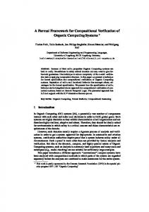
Eachsent connector can bevariable represented as a 5-tuple, similar the basic model: and to the input of another model or to thetooutputting model itself. C: = . A>. Compared to the basic mod Each connector can be representedC:as= a empty model ɛ. ε = < P, I, O, F, A> where P = Ø, I = Ø, O = Ø, F = Ø, A = , Sɛ=={s 4.2.2. Parallel where P = Ø, I = Ø, O = Ø, F = Ø, A = , S = {s 0 }, and Ø.Ø. where P = Ø, I = Ø, O = = , S = {s0 }, andT T= = 4.2.2. Parallel The parallel operator indica 4.2.2. 4.2.2.Parallel Parallel Paralleled The parallel operator indicates that two or more models can be parallel in the same cycle.models do not depend the integrated The parallel operator indicates that two or more models can be parallel in the same cycle. Paralleled Paralleled models do not depend on each other’s according to the dataflow. But if one model fails,cycle.model based on The parallel operator indicates that two or more models can be parallel in same HYDRUS and HYDRUS 2 sh the models integrated model based on the control will fail For example,in 1if of Figure 1,1fails, do not depend other’s to too. the dataflow. if oneschema model the integrated Paralleled models do on noteach depend on according each other’s according to But the dataflow. Butfails, one model 1, I1, O11, , F1, A1>, m2= 0, l, m ≥ 0}, and s20 • = {(s1i s20 , s1j s2m )∈T1 × T2 |, I > 0, l, m ≥ 0}. If si = (s1j, s2k ), Pei = Pe 1j ∪ Pe 2k , Iei = Ie 1j ∪ Ie 2k ,Int. OeiJ. Geo-Inf. = Oe 1j 2017, ∪ Oe6,2k47 , i 6= 0, and fe = (fe1 ↑fe2 ), which means fe1 and fe2 are performed simultaneously. ISPRS 9 of 24 The parallel operation is illustrated in Figure 6. It It is obvious thatthat we can m = mm1↑m 2= ↑ 2↑m 1 and = m1↑m 1↑m )↑m 3 = )m 1↑ = is obvious we obtain can obtain = m m =2↑m m1 ↑3=m(m 1 mm 2= m 2 ↑m1m and 2 ↑m 3 = 2(m 1 ↑m 2 ↑m 3 (mm 2↑m 3). ↑m ). ↑ (m 1 2 3 p1 m= m1↑m2 i1
p2
P= P1ÈP2 m1
I= I1ÈI2
i2
o1 O = O1ÈO2
m2
i3
o2 F = F1 ☉ F2
s0 s1 To clarify, we consider that m1 (s11, s21)
(s12, s21)
and m2 both have two states in addition to their respective initial
(s10, s20)
states. These states are denoted (s11, s21)
(s12, s22)
as s11, s12 of m1 and s21, s22 of m2.
Figure 6. The diagram definition of the Parallel operator.
Figure 6. The diagram definition of the Parallel operator.
4.2.3. Sequence 4.2.3. Sequence The sequence operator is the most familiar operation during integration. It indicates that m1 must The sequence is the operation during integration. It indicates thatbymthe 1 have finished its operator action before m2 most can befamiliar activated in the same cycle, which is generally caused must have finished its action before m 2 can be activated in the same cycle, which is generally caused dataflow. If the data of one or more input variables of m2 are from the output variables of m1 , then bythere the dataflow. If themdata or more input variables m2 are from the output variables m1, is a sequence Usually, there is one or moreof connectors between m1 and m2 ; weof denote 1 →mof 2 . one then m 1→m 2where . Usually, there is one or more connectors between m 1 and m2; we thisthere as m1is →a(csequence ↑ . . . ↑ c ) → m , c , . . . , and c are parallel. 1 2 1 k k 1→(care 1↑…↑c k)→m2,m where and denoteSuppose this as mthere two models I1 , O A1 >,parallel. m2 = , A1 = , 1 = , to parallel operation, we can define cm = c1 ↑ . . . ↑ck , and cm = , Ac = } the ’s1 inputs haveI =been by− m outputs. a ’s Ia^b = {iThe ∈ integration Ia| ∃o ∈ O mb.ofunction = ma.i>}can is the set of mb’s with inputsF = that been occupied a’sf ) ofb, the be represented F 1 have × Fc × F 2 , and f = (f 1by →fm c→ 2 outputs. ∈ F, which means that f 1 ∈F 1 , fc ∈F c , and f 2 ∈F 2 are performed in sequence. According to FSM, A = The integration the function be represented with 1 × Fc × Fmeans 2, and fthat = (f1m →f 2) ∈ A1 × Ac × A2 , and theofinitial state of can the model is s0 = , which c and m2F, are 1 ,c→f which means that f1∈F1, fc∈Fc, and f2∈F2 are performed in sequence. According to FSM, A = A1×Ac×A2, and the initial state of the model is s0 = , which means that m1, c and m2 are in initial states simultaneously. In addition, S = {s0} ∪ (S1\{s10} × Sc\{sc0} × S2\{s20}). The transition T is also the combination of T1, Tc and T2. We define T = T1 × Tc × T2 – s10•- sc0•- s20•. If si = (s1j, scl, s2k), then Pei = Pe1j ∪ Pecl ∪ Pe2k, Iei = Iej1 ∪ Iecl ∪ Ie2k − Iecl^e1j − Ie2kl^ecl, Oei = Oe1j ∪ Oecl ∪ Oe2k, i ≠ 0, fe = (fe1→fec→fe2). The sequence operation is illustrated in Figure 7.
ISPRS Int. J. Geo-Inf. 2017, 6, x FOR PEER REVIEW
10 of 24
represented as WOFOST → HYDRUS-1D and HYDRUS-1D → MODFLOW, respectively. ISPRS Int. J. Geo-Inf. 2017, 6, 47 of 22 Together these are equal to WOFOST → HYDRUS-1D → MODFLOW. The parameters of10the integrated model are the union of three sub-models’ parameters. The input variables should be the union of three variables except LAI, CH (three HYDRUS-1D’s input variables) and in initial statessub-models’ simultaneously. In addition, S = {sRD, 0 } ∪ (S1 \{s10 } × Sc \{sc0 } × S2 \{s20 }). The transition T Hb (a WOFOST’s input of variable). The variables union of three models’ output × Tthe is also the combination T1 , Tc and T2 output . We define T = T1are c × T 2 – s10 •− sc0 •− s20 •. If si = (s1j , variables. The function of the integrated model is the combination three sub-models. In the sc l , s2k ), then Pei = Pe 1j ∪ Pec l ∪ Pe 2k , Iei = Iej1 ∪ Iecl ∪ Ie 2k − Ieclˆe1j − Ieof 2klˆecl , Oei = Oe 1j ∪ Oec l ∪ Oe 2k , model, there are only two states: s 0 = (s10, s20, s30) (initial states) and s1 = (s11, s21, s31). i 6= 0, fe = (fe1 →fec →fe2 ). The sequence operation is illustrated in Figure 7.
p1 m= m1→m2
i1 I= I1IcI2 i2
p2
P= P1PcP2 O= m1
cm
m2
o1
O1OcO2
i3
o2 F = F1×Fc×F2
For simplicity, m1 and m2 both have one state besides their
s0
s1
initial respective states. These states are denoted as s11 of m1 and s21 of m2. Connector cm
(s10, sc0, s20)
(s11, sc1, s21)
always has two states: sc0 and sc1.
Figure 7. The diagram definition of the Sequence operator.
Figure 7. The diagram definition of the Sequence operator.
We can also obtain m = m1 →m2 →m3 = (m1 →m2 )→m3 = m1 →(m2 →m3 ). In our example model, Sometimes, there may be noHYDRUS-1D explicit dataflow between two In relations, a cycle, the successor WOFOST to HYDRUS-1D and to MODFLOW aremodels. sequence which can be models can begin to run if and only if the predecessor models have finished. The empty connector represented as WOFOST → HYDRUS-1D and HYDRUS-1D → MODFLOW, respectively. Together cɛthese , which similar the empty model, can be→ used to imply these sequences. of the integrated model areisequal to to WOFOST → HYDRUS-1D MODFLOW. The parameters are the union of three sub-models’ parameters. The input variables should be the union of three 4.2.4. Feedback sub-models’ variables except LAI, RD, CH (three HYDRUS-1D’s input variables) and Hb (a WOFOST’s input variable).operation The output variables aretwo thecycles unionof of the three models’ output variables. The or function A feedback occurs across model. It may act on one model on twoof the integrated model is the combination thethe model, there are only two states: different models, denoted with m1←m1 or of m1three ←m2. sub-models. This implies In that data are transferred from an s0 = (s10 , s20 , s30of ) (initial states) andins1 the = (sprevious , s , s ) output variable the later model cycle to the input variable of the former at the 11 21 31 . Sometimes, may be no explicit dataflow two models.cannot In a cycle, successor next cycle throughthere a connector, c. The second type ofbetween feedback operation exist the on its own. models can run if on anda only if the or predecessor models have The Additionally, empty connector Generally, it begin will betobased sequence parallel operation in a finished. single cycle. it iscε , which is similar to the empty model, can be used to imply these sequences. obvious that m1 and m2 can be understood as a model m’s different components, such that m1←m2 is equivalent to m←m. Thus, we need only to discuss the semantics of m1←m1 or (c→m1)←m1. 4.2.4. Feedback Suppose m1 = , A1 = , c = , Ac = . Let m =A(c→m 1)←m 1 and m = occurs ,two A =cycles . feedback operation across the model. It may act on one model or on two We can thus obtain thewith following P = P 1implies ∪ Pc, I =that I1 ∪ Ithe c, Odata = O1are ∪ Otransferred c, F = Fc × F1from = {fc} ×an different models, denoted m1 ←mconclusions. or m m . This ← 1 1 2 F1output , and Avariable = Ac × Aof 1. the Further, s 0 = (s c0 , s 10 ), S = {s 0 } ∪ S c \{s c0 }× S 1 \{s 10 } and T= {(s c0 , s 10 ), (s c0 , s 11 )} ∪ s c1•. If later model in the previous cycle to the input variable of the former at the next t∈{(s s10), (sc0,as11 )}, then the corresponding state stoperation = , P est = P ec ∪ e1, Iest = Iec ∪ Ie1, cyclec0,through connector, c. The second typetarget of feedback cannot exist on itsPown. Generally, Oitestwill = Oecbe∪ based Oe1, fe on = fc→f 1 . Otherwise, the formulae are the same as before, except that I est = I ec ∪ I - {i'}, a sequence or parallel operation in a single cycle. Additionally, it is obvious e1that m1 where transferred from the cycle’s The feedback operation is m illustrated in Figure 8.to and mi'2iscan be understood as alast model m’soutput. different components, such that 1 ←m2 is equivalent For example model, and HYDRUS-1D ←m1MODFLOW are the m←our m. Thus, we need onlyWOFOST to discuss← theHYDRUS-1D semantics of m . 1 ←m 1 or (c→m1 )← feedback relation. They also can be represented as cascade formation WOFOST ← HYDRUS-1D Suppose m1 = , A1 = , c = , Ac = . ←Let MODFLOW. of=this is omitted. m = (c→m1 )The ←m1detail and m , A = .
ISPRS Int. J. Geo-Inf. 2017, 6, 47
11 of 22
We can thus obtain the following conclusions. P = P1 ∪ Pc , I = I1 ∪ Ic , O = O1 ∪ Oc , F = F c × F 1 = {fc } × F 1 , and A = Ac × A1 . Further, s0 = (sc0 , s10 ), S = {s0 } ∪ Sc \{sc0 }× S1 \{s10 } and T= {(sc0 , s10 ), (sc0 , s11 )} ∪ sc1 •. If t∈{(sc0 , s10 ), (sc0 , s11 )}, then the corresponding target state st = , Pest = Pec ∪ Pe1 , Iest = Iec ∪ Ie1 , Oest = Oec ∪ Oe1 , fe = fc →f 1 . Otherwise, the formulae are the same as before, except that Iest = Iec ∪ Ie1 - {i'}, where i' is transferred from the last cycle’s output. The feedback operation is illustrated in Figure 8. For our example model, WOFOST ← HYDRUS-1D and HYDRUS-1D ← ISPRS Int. J. Geo-Inf. 47 11 of 24← MODFLOW are2017, the6,feedback relation. They also can be represented as cascade formation WOFOST HYDRUS-1D ← MODFLOW. The detail of this feedback is omitted. p2
p1 m= m1←m1 i1
P= P1ÈPc m1
I= I1ÈIc
i2
c
o1
mb O=O1ÈOc
ma
i3
o2 F = F1 È Fc×F1
s0
s1 Model m1 has the states s10, s11, and s12. Connector c has two (sc0, s11)
states: sc0, and sc1.
(sc0, s20) (sc1, s21)
Figure The diagram definition Feedback operator. Figure 8. 8. The diagram definition of of thethe Feedback operator.
4.2.5. Select 4.2.5. Select TheSelect Select operation operation makes different sub-models or sub-model groupsgroups possible. The makeschoosing choosingbetween between different sub-models or sub-model These sub-models or sub-model groups may have similar functions andfunctions different implementation possible. These sub-models or sub-model groups may have similar and different methods, or facemethods, different or initial boundaryinitial conditions. For example, in the integration of HYDRUS implementation faceordifferent or boundary conditions. For example, in the and WOFOST, before the and crop sprouts and before after thethe crop harvests, WOFOST needthe not work the time. integration of HYDRUS WOFOST, crop sprouts and after crop all harvests, Suppose =
, m =
, A = , and A = . If m = m
, if A1the = , and A2g1= is .then If 2 , this is performed, if gm2 =ism satisfied, then m2 isthat performed. In Select operation, guardthen expression mm = 1 or and 1◊m2, this implies if the guard expression g1 iseach satisfied, m1 is has a parameter Pg , inputthen variable Ig , and output variable set O can define P = Phas performed, or if g2 set is satisfied, m2 is set performed. In Select operation, each guard expression g . We 1 ∪aP2 ∪ Pg1 ∪ Pset I1 ∪ Ivariable =O ∪ Og1 ∪set Og2 = {g ×=FP1 1∪∪ {g setIg2Ig,, O and output O,g.and We Fcan define P21∪, gP2g1} ∪×PF 2 . parameter g2 ,PIg,=input 2 ∪ I g1 ∪ 1 ∪ O2variable 1 , g2 } P k k S21 ∪∪ O S12 ∪× O {sg120∪}, O s0g2=, {s , s }, and T = ∪ (T × T ) ∪ ( ∪ g2,For I = the I1 ∪FSM I2 ∪ A, Ig1 S ∪ =Ig2{s, 10 O} × =O and F = {g 1 , g 2 } × F 1 ∪ {g 1 , g 2 } × F 2 . For the A,2 )), 10 20 i=0 1 2i0 i=0 (TFSM 1i0 × T k k are existing transitions that , s(T m1 and ) for S where = {s10} ×T1i0 S2 ∪and S1 ×T{s 20}, s0 not = {s10 , s20}, and T = ∪ i=0(T 1 × imply T2i0) ∪ (s (∪1ii=0 × Tmodel 2)), where T1i0(sand T2i0 aremodel not 10 )1i0for 2i0 2i , s20 m2 , andtransitions where s1i and stand for arbitrary states of m and m , respectively. Suppose s =
. If = (s1j , s20states ), thenofPm = P ∪ P ∪ P , I = I ∪ I ∪ I , O = O ∪ O ∪ O , f = (f stand forsiarbitrary 1 and m 2 , respectively. Suppose s i =
. If s i = (s 1j , s 20 ), then P eg1 , e e 1j g1 e 1j g1 e e 1j g1 g2 e g2 e g2 f g2 Pee == O Pee1j2j∪∪OPg1g1∪ ∪ ∪ OP ∪POe2jg2 =P e1j )∪ & Pg1fe ∪1j .PIfg2s, iI= e =(sI10 e1j,∪s2j Ig1),∪then I g2, O Og2P,g2fe,=Ie(f=g1,Ife 2j g2)∪ &Ig1 fe1j∪ . IfI sg2i =, O (se10=, sO 2j), ∪ ,Pfg1e = e 2jthen g1e = , g ) & f . The select operation is illustrated in Figure 9. ∪ (g Pg2 I e = I e2j ∪ I g1 ∪ I g2 , O e = O e2j ∪ O g1 ∪ O g2 , f e = (g 1 , g 2 ) & f e2j . The select operation is illustrated in e 2j 1 2 Figure 9. Similarly, we can obtain m = m1 ◊ m2 = m2 ◊ m1 and m = m1 ◊ m2 ◊ m3 = (m1 ◊ m2) ◊ m3 = m1 ◊ (m2 ◊ m3). In the example, WOFOST is integrated with select operation WOFOST ◊ ɛ.
ISPRS Int. J. Geo-Inf. 2017, 6, 47
12 of 22
Similarly, we can obtain m = m1 ♦ m2 = m2 ♦ m1 and m = m1 ♦ m2 ♦ m3 = (m1 ♦ m212 )♦ m = m1 ♦ ISPRS Int. J. Geo-Inf. 2017, 6, 47 of 24 3 (m2 ♦ m3 ). In the example, WOFOST is integrated with select operation WOFOST ♦ ε. p1 m= m1◊m2
p2
p1 m= m1◊m2
P= P1ÈP2ÈPg1ÈPg2
I= I1ÈI2
i2
ÈIg1ÈIg2
m1 m2
g2
i3
O = O1ÈO2 o1 ÈOg1ÈOg2
i1
I= I1ÈI2
i2
ÈIg1ÈIg2
o2
i3
F = {g1, g2}×F1∪{g1, g2}× F2
s0
g2∧g1 ¬ g1∧g2
g2
O = O1ÈO2 o1 ÈOg1ÈOg2
m2
o2
s0
¬
g2∧g1
m1
F = {g1, g2}×F1∪{g1, g2}× F2
s1
¬
(s10, s20)
P= P1ÈP2ÈPg1ÈPg2 g1
g1 i1
p2
g2∧g1
(s11, s20)
¬ ¬ g1∧g2
¬
g2∧g1
a. S1 = {s10, s11}, S2 = {s20, s21}
g1∧g2
(s11, s20)
¬
g1∧g2
(s12, s20) ¬ ¬
(s10, s20)
(s10, s21) ¬
s1
(s10, s21)
g2∧g1 g1∧g2
(s10, s22)
b. S1 = {s10, s11, s12}, S2 = {s20, s21, s22}
Figure 9. The diagram definition of the Select operator. (a) S1 = {s10 , s11 }, S2 = {s20 , s21 }; Figure 9. The diagram definition of the Select operator. (a) S1 = {s10, s11}, S2 = {s20, s21}; (b) S1 = {s10, s11, (b) S1 = {s10 , s11 , s12 }, S2 = {s20 , s21 , s22 }. s12}, S2 = {s20, s21, s22}.
4.2.6. 4.2.6.Iterate Iterate environmental simulations, simulations, different such as,as, forfor example, InInenvironmental differenttime timesteps stepsmust mustbebepermitted, permitted, such example, from from simulation hourly simulation (e.g., to asimulate a fungal infestation) updecades to several decades for studies. hourly (e.g., to simulate fungal infestation) up to several for sustainability sustainability studies. Although most models work iteratively, the framework only defines the iterate operation that is Although most models work iteratively, the framework only defines the iterate operation that used when the model needs to perform many cycles while other models that will be integrated only is used when the model needs to perform many cycles while other models that will be integrated perform one cycle. The typical scenario is when models with different time steps are to be integrated: only perform one cycle. The typical scenario is when models with different time steps are to be the model with the shorter time step should iterate many times while other only executes integrated: the model with the shorter time step should iterate many timesthe while themodel other model once. In integrated algebra, we use µm to denote a model’s iteration. only executes once. In integrated algebra, we use μm to denote a model’s iteration. Consider modelmm1 =1
Aand =, and 1 , If 1, which imply m1 is m performed until the guard g is not satisfied has parameter mμm = µm imply until theexpression guard expression g is not(gsatisfied (g hasset parameter 1 , which 1 is performed PgP , input variable set Igset , and variable set Og), set thenOwe obtain P = obtain Pg ∪ P1, P I ==IgP∪gI1∪ ,O set variable Ig ,output and output variable then we can P1=, O I g= Ig ∪ I1 , g , input g ), can ∪ O 1, and F = {g} × F1 ∪ {g} × {fɛ}. O = Og ∪ O1 , and F = {g} × F 1 ∪ {g} × {f ε }. For the FSM A = , we define s0 = s10. For convenience when integrating with other For the FSM A = , we define s0 = s10 . For convenience when integrating with other operations, the running state of the model is extended to comprise three types of states: the first operations, the running state of the model is extended to comprise three types of states: the first running state sf∈Sf, where sf = {Pef, Ief, Oef, fef}; the iterative running state Sit; and the state of end Sf , where running state sf ∈that s = {P , Ief ,the Oeftransitions , f ef }; the iterative running state Sit ; Tand the state of end iteration se, such S = {s0, sfe}∪Sf∪Sefit and according to these states are f, Tit, and Te, iteration s , such that S = {s , s } ∪ S ∪ S and the transitions according to these states are Tf∪, T e 0 e (s10, fs1i)∈T it 1. Let s1i = ; then Pef = Pe1i ∪ Pg, Ief = Ie1i respectively. If (s10, s1i)∈Tf, then Igit, , and Te , respectively. (s10 ,fefs=1i g)∈×Tffe1i, .then (s10 , (s s1i1i,)∈ Oe 1i e 1i ∪ Pg , I ef = 1 . 1Let Oef = Oe1i ∪ OgIf , and For each s1jT )∈T , I ≠s0, (s1i
; = O ∪ O , and f = g × f . For each (s , s ) ∈ T , I 6 = 0, (s , s ) ∈ T . Let s =ee
,f Pee>; = P g, Iee =PIg, O eeP = O g , and f ee = g. Then, Te = {(s i , s e )| s i ∈S f ∪ S it }. Figure 10 illustrates the iterate Ofeit then, = ∪ P , I = I ∪ I , O = O ∪ O , and f = g × f . For the end iteration e 1j g eit e 1j g e 1j g e 1j eit eit eit eit operation of the model. state, let se = < Pee , Iee , Oee , fee >, Pee = Pg , Iee = Ig , Oee = Og , and fee = g. Then, Te = {(si , se )| si ∈Sf ∪ Sit }. Figure 10 illustrates the iterate operation of the model.
ISPRS Int. Int. J. J. Geo-Inf. Geo-Inf. 2017, 2017, 6, 6, 47 47 ISPRS
13 of of 22 24 13
p1 m= μm1
p2
P= PgÈP1 g=False
i1
g
I= IgÈI1
i2
o1
g= True
m1
O = OgÈO1
i3
o2 F = {g} × F1∪{g}×{fɛ}
s0
s1
g
¬g
g
sf
sit
se
¬g Figure Figure 10. 10. The The diagram diagram definition definition of of the the Iterate Iterate operator. operator.
4.2.7. 4.2.7. Combine Iterate with Other Operators Operators Because operation should not be alone,alone, it is combined with the with parallel, Because the theiterate iterate operation should notused be used it is combined thesequence, parallel, feedback, select operations. framework M↑µM, M →µM, µM→ M, µM← M, M←µM, and sequence,and feedback, and select The operations. Theuses framework uses M↑μM, M→μM, μM→M, μM←M, M ♦µM toand denote these M←μM, M◊μM to combinations. denote these combinations. M ↑µM represents µm22, i.e., M↑μM represents aa model model that that parallels parallels an an iteration iteration of of another another model. model. Let Let m m == m m11↑↑μm model parallels an an iteration iteration of model m22.. Obviously, Obviously, if the iteration is performed n times, model m m11 parallels times, then then it it can be extended to n cycles in which m m is only performed in one cycle, while in any other cycles, ↑ can be extended to n cycles in which m11↑m22 is only performed εɛ↑↑m m22 is performed, and F == FF11 ∪∪ FFm2 For FSM FSM A, performed, such suchthat thatPP= =P1P∪ 1 ∪PP m2, ,I I==I 1I1∪ ∪ IIm2 m2, O O == O O11 ∪ Om2 m2,, and . .For m2 m2 SS == {s s’itit, ,ssee},},ss00==(s(s1010 =10(s, 10 ’ =11,(ss11 , ss2fit =), (s sit10= , s2it snf {s00, sff, sff’, sitit,, s’ , s, 20s20 ), ),sf =sf (s s2f,),s2fsf), ’ =sf(s 2f), , s(s 2it10 ), ,s’sit2it=),(ss’11it, s=2it(s ), 11 snf se ), = (s 11, sse2e= ). (s T1 10×, sT2f2),− {((s , s2f s2f10)), s2it ),(s10 , s2e ))}.from Additionally, to1 T11=,Ts12e×).TT2 −= {((s (s11 , s10 2f)), ((s),10(s , s112it,),(s , s((s 2e))}. state (s10, sfrom 20) to state state (s (s10 11, s2e 10 , Additionally, 20),) m state (s11execute , s2e ), m1only should execute once execute and m2 should onceintegration at least. The is should once and monly 2 should once atexecute least. The is integration illustrated in illustrated Figure 11. in Figure 11. M →µM and µM →M imply that a model’s iteration performs with another model in sequence. M→μM μM→M They extended as as what is defined in the of parallel and iteration. The former They can canalso alsobebe extended what is defined incombination the combination of parallel and iteration. The is extended to a sequence M → M in the first cycle and a series of cycles involving ε → M. Similarly, the former is extended to a sequence M→M in the first cycle and a series of cycles involving ɛ→M. latter is extended to aisseries of cycles involving ε→Minvolving first and then M→M in the lastM→M cycle. Similarly, the latter extended to a series of cycles ɛ→Ma sequence first and then a sequence The integration illustrated in Figure 12. in the last cycle.isThe integration is illustrated in Figure 12. The with iteration is similar to the The combination of select The combination combinationofoffeedback feedback with iteration is similar to sequence. the sequence. The combination of with is simple as well.asThus, are omitted in this in paper. selectiteration with iteration is simple well. these Thus,combinations these combinations are omitted this paper.
ISPRS Int. J. Geo-Inf. 2017, 6, 47 ISPRS Int. J. Geo-Inf. 2017, 6, 47
14 of 22 14 of 24
p1 m= m1↑μm2 i1
I= I1È
i2
IgÈI2
p2
P= P1ÈPgÈP2
g=False
i3
o1
O = O1 ÈOgÈO2
m1 g
o2 m2 g= True
F = F1 ×{g} × F2∪F1 ×{g}×{fɛ}
s0
s1 ¬g
g∧m2
g∧m2 (s11, s2f)
(s11, s2it)
m1˅g∧m1m2
(s10, s20)
(s11, s2e)
m1˅g∧m1m2 (s10, s2 it)) g∧m2 g∧m2
(s10, s2f)
g∧m2
¬g
From state (s10, s20) to state (s11, s2e), m1 should execute only once and m2 should execute at least once.
ISPRS Int. J. Geo-Inf. 2017, 6, 47
15 of 24
Figure 11. The diagram definition of M↑µM. Figure 11. The diagram definition of M↑μM. p2
p1
P= P1ÈPgÈP2
m= m1→μm2 μm2 i1
I= I1È
i2
IgÈI2
g=False
g m1
i3
O = O1 ÈOgÈO2
m2
c
o1 o2
g= True F = F1 ×Fc × F2∪F1 ×Fc×{fɛ}
s0
s1
g∧m1c m2
g∧m2
g∧m2 (s11, sc1, s2f)
(s10, sc0, s20)
¬g (s11, sc1, s2e)
(s11, sc1, s2it) ¬g (a)
Figure 12. Cont.
I= I1È
i2
IgÈI2
μm1 g
p1
P= P1ÈPgÈP2
m= μm1→m2 i1
p2
g=False m2
c
m2
O = O1 ÈOgÈO2
o1
g∧m1c m2
g∧m2
g∧m2 (s11, sc1, s2f)
(s10, sc0, s20)
¬g (s11, sc1, s2e)
(s11, sc1, s2it) ¬g
ISPRS Int. J. Geo-Inf. 2017, 6, 47
15 of 22
(a) p2
P= P1ÈPgÈP2
m= μm1→m2 i1
I= I1È
i2
IgÈI2
p1
μm1 g
g=False m2
i3
m2
c
O = O1 ÈOgÈO2
o1 o2
g= True F = F1×Fc×F2∪{fɛ}×Fc×F2
s0
s1
g∧m1
g∧m1
g∧m1 (s10, sc0, s20)
(s1it, sc0, s20)
(s1f, sc0, s20)
¬g∧m2 (s11, sc1, s2e)
¬g∧m2 (b) Figure The diagram definition M→Μm; (b)µM μM→M. Figure 12. The12. diagram definition of Mof→M→μM. µM. (a) (a) M→ Mm; (b) →M.
5. Complex Integrated Model 5.1. Model Graph With these basic operators, a complex model can be integrated from simpler models, even basic models. A result of an Iterate operation or Select operation is taken as a sub-model in the frame. From the perspective of the integrator, many sub-models can be synthetized together with connectors and corresponding message transferring channels. These sub-models may involve both basic models and integrated models, such that the sub-models and channels compose a graph called a model graph. The model graph can be illustrated as in Figure 13, which is a simple example. 5.2. Formal Semantics of Model Graph Given three finite alphabets ΣM, ΣC, and ΣVar as the available labels for the models, connectors and variables, respectively, the integration of the models is defined with a labeled multidigraph with ports, as follows: GM : = . M and C are two finite sets of vertices that denote models and connectors, respectively. M includes basic models and pre-existing integrated models. L ⊆ (M × OVar) × (C × IVar) ∪ (C × OVar) × (M × IVar) is a set of direct edges, which indicates the dataflow among the sub-models and connectors. The edge set includes both sequence and feedback related dataflow. To distinguish them, we use the label ls for sequence edge and lb for feedback edge, and L = Ls ∪ Lb . P, I, and O are the set of parameters, input variables, and output variables, respectively, and Var = P ∪ I ∪ O. ι = ιM ∪ ιC . ιM = (ιp, ιi, ιo): M →PVar × IVar × OVar assigns a parameter variable (port) set, an input variable (port) set and an output variable (port) set to each model, with ιp(M) = PM, ιi(M) = IM, ιo(M) = OM, and ι(M) = (PM, IM, OM).
ISPRS Int. J. Geo-Inf. 2017, 6, 47
17 of 24
ISPRS Int. J. Geo-Inf. 2017, 6, 47
m1.o1 c1.i1
m1.i1 m1 m1.i2
m1.o2 m1.o3
c2.i2 m2.i1 m2.i2
m2
m3
c2
c2.o
c3
c3.o
m4.i2
m4.o1
m4
m4.i3
m2.o2 c3.i1 c3.i2 c3.i3
m2.i3
m3.i1
c1.o
c1
m4.i1 c2.i1
16 of 22
m5.o1
m5
m5.i1
m5.o2
m3.o1 m3.o2
(a) p1
i1 o1 o2 m1 i3 o3
i1
i1
o c1
c2 o
i2
i1
i1 i2 o1 m4 i3
o1 o2
i1 i2 o2 m2
i3
…
… il I= ÈM,CI
pl
P= ÈM,CPl
m
i2
p2
i1 i2 c 3 o i3
i1m5
o1 o2
ok O= ÈM,CO
o1 i1 m3 o2 F A
(b) Figure The example a model graph.(a) (a)The The example of of a model graph; (b) The unified view of view of Figure 13. The13. example of a of model graph. example a model graph; (b) The unified an integrated model based on a. an integrated model based on a.
In the graph model, there are two types of relations between any two sub-models. The first is the partial which based sequence operator. If there is variable a path between Similarly, ιC ordering = (ιp, ιi,relation, ιo): C → PVaris × IVaron×theOVar assigns a parameter (port) set, an two sub-models m h and mt such that mh→m1, m1→m2, …, mi→mt, we can say that mh →→ mt and call input variable (port) set and an output variable (port) set to each connector, with ιp(C) = PC, ιi(C) = IC, it order. It is obvious that mt begins to perform after mh has finished in one cycle. Another type is ιo(C) = OC, and ι(C) = (PC, IC, OC). called noninterference, i.e., two sub-models perform in parallel without mutual interference. s: L → M OVar ∪ C can × OVar t: L first → Msearch × IVar ∪ C ×toIVar are two mapsfrom indicating As× a result, we obtainand a width algorithm construct a model a modelthe source and target model/connector of be anseen edge. A map n: Mgraph × OVar ∪C14). × OVar ∪M × OVar ∪C × OVar→{0} graph. The algorithm can in the following (Figure ∪ N is defined for the source and target of the edge to indicate the produce rate and consumption rate, respectively. lM: M → ΣM, lC: C → ΣC and lVar: L → ΣVar are three maps describing the labeling of the models, connectors and variables.
5.3. Construct Complex Integrated Model The model graph is intuitive, such that the integrator can use it easily to represent the interaction of integrated models. At the same time, the IEM tools can use the properties of the graph to check the
ISPRS Int. J. Geo-Inf. 2017, 6, 47
17 of 22
integrated schema. In running time, the structure of the graph can be used to monitor the procedure of the simulation. Once errors occur, the IEM tool can locate them with the graph as well. In the graph model, there are two types of relations between any two sub-models. The first is the partial ordering relation, which is based on the sequence operator. If there is a path between two sub-models mh and mt such that mh →m1 , m1 →m2 , . . . , mi →mt , we can say that mh →→ mt and call it order. It is obvious that mt begins to perform after mh has finished in one cycle. Another type is called noninterference, i.e., two sub-models perform in parallel without mutual interference. As a result, we can obtain a width first search algorithm to construct a model from a model graph. The algorithm can be seen in the following graph (Figure 14). ISPRS Int. J. Geo-Inf. 2017, 6, 47
18 of 24
//Algorithm for constructing a unified view of the integrated model from a model graph. Input: C = {c1, c2, …}; //The set of connectors SM = {sm1, sm2,…}; //The set of sub-models //The set of edges L = {l1, l2, …}; Output: M = ε; //Integrated model Variable: TM = Ø; //The set of temporal models TSM = Ø; //The set of temporal sub-models tm, tm`; //TM’s element tsm; // TSM’s element thm; //Temporary head model Begin Integration foreach sm∈SM if ∄ c ∈ C s.t. (c, sm) ∈L or (∃c ∈ C s.t. (c, sm) ∈L and ∄sm’ ∈SM s.t. (sm’, c) ∈L ){ TM = TM È {sm }; //Find out all the first group of sm SM = SM - {sm }; } //End of if while TM ≠Ø { foreach tm∈TM //Integrating each first Parallel models group foreach c∈C and (tm, c) ∈L foreach tm`∈TM - {tm } if((tm`, c) ∈L){ tm = tm ↑ tm`; TM = TM - {tm’ }; } foreach tm∈TM{ // TM has been updated. TSM = Ø; thm = ε; foreach c∈C and (tm, c) ∈L foreach sm∈SM and (c, sm) ∈L{ TSM = TSM È {sm}; SM = SM - {sm}; } foreach tsm∈TSM //Find out Parallel models if ∃tsm’ ∈TSM and tsm’≠tsm s.t. tsm’→tsm or tsm’ →→tsm{ TSM = TSM - {sm}; SM = SM È {sm}; } foreach tsm∈TSM //Integrating a group of Parallel models thm = thm↑tsm; tm = tm→thm; }//End of foreach tm∈TM }//End of while TM ≠Ø foreach tm∈TM m = m↑tm; End Integration
//Integrating Sequence models
//Integrating all Parallel models at last
Figure 14. The algorithm for constructing a unified view of the integrated model from a model graph.
Figure 14. The algorithm for constructing a unified view of the integrated model from a model graph.
ISPRS Int. J. Geo-Inf. 2017, 6, 47
18 of 22
From the algorithm, we know that the integration of many sub-models can also be taken as a model. 6. Results Although there are few formal frameworks for IEM being studied specially, each IEM platform has its own potential formalist basis. We compare our formal framework with several platforms or standards to illustrate our framework’s characteristics (in Table 1). The selected platforms are OMS3 [39], OpenMI [8] and ESMF [40]. Table 1. The comparison with other platforms. Our Framework Technological Basis
Formalism
Dataflow sequence feedback select iterate
Integration reusable
OMS3
OpenMI
ESMF
/
Object-Oriented
/
DSL + POJO + Annotation
Interface-Based
Component-Based Mediator Pattern
yes yes yes yes yes
yes yes yes no no
yes yes yes extra codes extra codes
yes yes yes extra codes extra codes
easy
difficult
difficult
difficult
From the comparison, we can see that there are some advantages embedded in our framework. The formal framework can be used as the semantic basis of an IEM Domain Specific Language (DSL) with which the complicated model can be integrated from pre-existing models. Based on the framework, a light weighted IEM DSL named irDSL (integration-reusable Domain Specific Language) has been developed in our recent work. In Appendix A, some code snippet with irDSL for the integrated model in Figure 1 is listed. The additional details of irDSL will be discussed in another paper. 7. Conclusions and Future Work In this paper, a formal framework for the IEM system is proposed. In the framework, the features of the model are divided into two parts, i.e., the static and dynamic features. The static features include the traditional parameters, input variables, output variables, and functions of the model. The dynamic feature is the transformation of the static features during the simulation and is represented as an FSM, which adapts the integrated model to dynamic application scenarios. Based on the framework, a unified definition of the model is proposed that makes the integrated model more manageable and reusable, as are the simple models. The integration is also represented as a multidigraph with port. An algorithm is used to explore its sufficiency such that there is a unified representation for a multidigraph. Our proposed definition can also be used as the interface between specification and formal verification. Based on the framework, it supports integration verification at a specified time (similar to [34,41]) such that the integration specification can be proven to be correct before its implementation; thus, an iterative cycle between the implementation and the specification can be avoided. At the same time, global understanding of the integration is increased, which makes the application easy to understand and, therefore, easy to maintain. Future work should address the enhancement of this tool by supporting the proposed methodology with additional automation features. Acknowledgments: The authors are grateful to Professor Honggang Luo for his suggestion. We also thank J. Zhou and Peña-Haro for helpful discusses and suggestions. This work was supported by National Natural Science Foundation of China under Grant No. 61402210 and 60973137, Program for New Century Excellent Talents in University under Grant No. NCET-12-0250, Major Project of High Resolution Earth Observation System with Grant No. 30-Y20A34-9010-15/17, “Strategic Priority Research Program” of the Chinese Academy of Sciences with Grant No. XDA03030100, Gansu Sci.&Tech. Program under Grant No. 1104GKCA049, 1204GKCA061 and 1304GKCA018, The Fundamental Research Funds for the Central Universities under Grant No. lzujbky-2016-140,
ISPRS Int. J. Geo-Inf. 2017, 6, 47
19 of 22
Gansu Telecom Cuiying Research Fund under Grant No. lzudxcy-2013-4, Google Research Awards and Google Faculty Award, China. Author Contributions: Gaofeng Zhang and Qingguo Zhou designed the framework. Yan Li, Chong Chen, Rui Zhou and Dan Chen tested the design. Conflicts of Interest: The authors declare no conflict of interest.
Appendix A. Some Code Snippet with irDSL for the Integrated Model in Figure 1. The following is a code snippet with irDSL for the integrated model in Figure 1. The conceptual integrated model is not bound to any concrete application and can be reused easily. In a concrete simulation, just as in Peña-Haro’s example [31], a hypothetical simplified two-dimensional-vertical flow system with a height of 20 m and a length of 200 m is used. Two different spatial discretizing schemas (such as Schema 1 with 2 zones and Schema 2 with 5 zones) are intended to be adopted, for comparison with traditional integration. Qualitatively, it can be seen that instantiation of the model needs relative few codes based on the conceptual integrated model. //Conceptual integrated model named WOHYMO; model WOHYMO{ model WOFOST(“path_WO”); //import basic WOFOST model; // path_WO: the path of jar file including the POJO of WOFOST; model HYDRUS_1D(“path_HY”); //Ditto; model MODFLOW(“path_MO”); //Ditto; //A select control for WOFOST used to specify that the WOFOST // begins to run after the crop germinates. select is_WOFOST_RUN { //Control flow if (!before_Emergence) WOFOST; // WOFOST doesn’t run until a crop emergency } //A connector for LAI (Leaf Area Index) which is produced by WOFOST // and consumed by HYDRUS as its one boundary condition. connector LAI_WO_HY{ // the ordinary connector; in lai1; out lai2; //input and output; expr expr(lai2=lai1); //indicates ordinary connector; } //simplified link for ordinary connector, implying a sequence operator; forward link_LAI_WO_HY{ source WOFOST.lai; target HYDRUS_1Dconn1.lai; } //A connector for vBot in HYDRUS (or recharge in MODFLOW) which represents // the water flows from unsaturated zone to saturated zone, which is produced by // HYDRUS and consumed by MODFLOW as its boundary condition. connector vBot_HY_MO{ // the recharge from HYDRUS to MODFLOW; in vBot; //input, weak typing, will be taken as an array; out recharge; //output; expr expr(recharge = vBot)); // has same recharge in a zone; } forward link_ vBot_HY_conn { source HYDRUS_1D.vBot; target vBot_HY_MO.vBot; }
ISPRS Int. J. Geo-Inf. 2017, 6, 47
20 of 22
forward link_ recharge_conn_HY { source vBot_HY_MO.recharge; target MODFLOW.recharge; } //A connector for Hb (pressure head) from MODFLOW to HYDRUS H or Hb is // produced by MODFLOW and transferred to HYDRUS-1D as its boundary // condition. connector Hb_MO_HY { // the H or Hb from MODFLOW to HYDRUS; in H; //input, weak typing, ; out Hb; //output, weak typing, will be taken as an array; expr expr(Hb = H); } backward link_Hb_MO_conn { source MODFLOW.H; target Hb_MO_HY.H; }
//implying a feedback operator;
forward link_ Hb_conn_HY { source Hb_MO_HY.Hb; target HYDRUS_1D.Hb; } relation m2o ; //m2o relation, for extendability; relation o2m < MODFLOW, HYDRUS_1D >; //o2m relation; //other codes are omitted due to space limitations. } //Instance of WOHYMO with the 5 zones model WOHYMO WOHOMO_5 { //instance definition; model WOFOST inst_WOFOST [5]; //5 instances of WOFOST; model HYDRUS inst_HYDRUS [5]; //5 instances of HYDRUS; model MODFLOW inst_MODFLOW; //1 instances of MODFLOW; for i in [1..5] //o2o relation; inst_WOFOST [i] ->inst_ HYDRUS [i]; inst_HYDRUS [1..5] ->inst_ MODFLOW; //5 inst_HYDRUSes relates to 1 inst_MODFLOW; inst_MODFLOW ->inst_HYDRUS [1..5]; //1 inst_MODFLOW relates to 5 inst_HYDRUSes; } //instance of ex16_WOHYMO with the 2 zones model WOHYMO WOHOMO_2 { //instance definition; model WOFOST inst_WOFOST [2]; //2 instances of WOFOST; model HYDRUS inst_HYDRUS [2]; //2 instances of HYDRUS; model MODFLOW inst_MODFLOW; //1 instances of MODFLOW; for i in [1..2] //o2o relation; inst_WOFOST [i] ->inst_ HYDRUS [i]; inst_HYDRUS [1..2] ->inst_ MODFLOW; //2 inst_ HYDRUSes relates to 1 inst_ MODFLOW; inst_MODFLOW ->inst_HYDRUS [1..2]; //1 inst_MODFLOW relates to 2 inst_HYDRUSes; }
References 1.
Bailey, G.W.; Mulkey, L.A.; Swank, R.R. Environmental implications of conservation tillage: A system approach. In A System Approach to Conservation Tillage; D’Itri, F.M., Ed.; Lewis Publishers Inc.: Chelsea, MI, USA, 1985; pp. 239–265.
ISPRS Int. J. Geo-Inf. 2017, 6, 47
2. 3. 4. 5. 6.
7.
8. 9.
10.
11. 12.
13. 14. 15.
16. 17. 18.
19. 20. 21. 22.
23. 24.
21 of 22
Cohen, Y. Pollutants in a Multimedia Environmental; Plenum Press: New York, NY, USA, 1986. Mackay, D. Multimedia Environmental Models: The Fugacity Approach; Lewis Publishers: Michigan, MI, USA, 1991. Walters, C.J. Adaptive Management of Renewable Resources; Macmillan Publishing Co.: New York, NY, USA, 1986. Voinov, A.; Shugart, H. ‘Integronsters’, integral and integrated modelling. Environ. Model. Softw. 2013, 39, 149–158. [CrossRef] Laniak, G.F.; Olchin, G.; Goodall, J.; Voinov, A.; Hill, M.; Glynn, P.; Whelan, G.; Geller, G.; Quinn, N.; Blind, M.; et al. Integrated environmental modelling: a vision and roadmap for future. Environ. Model. Softw. 2013, 39, 3–23. [CrossRef] Leavesley, G.H.; Markstrom, S.L.; Brewer, M.S.; Viger, R.J. The Modular Modelling System (MMS)—The physical process modelling component of a database-centered decision support system for water and power management. Water Air Soil Pollut. 1996, 90, 303–311. [CrossRef] OpenMI. The OpenMI Open Midel Interface Project. 2016. Available online: https://publicwiki.deltares.nl/ display/OPENMI/Version+2.0 (accessed on 24 December 2016). David, O.; Markstrom, S.L.; Rojas, K.W.; Ahuja, L.R.; Schneider, W. The object modelling system. In Agricultural System Models in Field Research and Technology Transfer; Ahuja, L.R., Ma, L., Howell, T.A., Eds.; Lewis Publishers: Boca Raton, FL, USA, 2002; pp. 317–344. David, O.; Ascough, J.C., II; Lloyd, W.; Green, T.R.; Rojas, K.W.; Leavesley, G.H.; Ahuja, L.R. A software engineering perspective on environmental modelling framework design: The object modelling system. Environ. Model. Softw. 2013, 39, 201–213. [CrossRef] Hill, C.; DeLuca, C.; Balaji, V.; Suarez, M.; da Silva, A. The architecture of the earth system modelling framework. Comput. Sci. Eng. 2004, 6, 18–28. [CrossRef] Thurman, D.A.; Cowell, A.J.; Taira, R.Y.; Frodge, J. Designing a collaborative problem solving environment for integrated water resource modelling. In Brownfields: Multimedia Modelling and Assessment; Whelan, G., Ed.; WIT Press: Southampton, UK, 2004. Aquaveo. Water Modelling Solutions; Aquaveo: Provo, UT, USA, 2012; Available online: http://www.aquaveo. com/ (accessed on 8 December 2013). Peckham, S.D. Evaluation of model coupling frameworks for use by the Community Surface Dynamics Modelling System (CSDMS). In Proceedings of the MODFLOW and MORE, Golden, CO, USA, 18 May 2008. van Ittersum, M.K.; Ewert, F.; Heckelei, T.; Wery, J.; Olsson, J.A.; Andersen, E.; Bezlepkina, I.; Brouwer, F.; Donatelli, M.; Flichman, G.; et al. Integrated assessment of agricultural systems e a component-based framework for the European Union (SEAMLESS). Agric. Syst. 2008, 96, 150–165. [CrossRef] Parker, D.; Manson, S.; Janssen, M.; Hoffmann, M.; Deadman, P. Multi-agent systems for the simulation of land-use and land-cover change: A review. Ann. Assoc. Am. Geogr. 2003, 93, 314–337. [CrossRef] Zhao, J.; Cai, X.; Wang, Z. Comparing administered and market-based water allocation systems through a consistent agent-based modelling framework. J. Environ. Manag. 2013, 123, 120–130. [CrossRef] [PubMed] Zhao, G.; Bryan, B.A.; King, D.; Luo, Z.; Wang, E.; Bende-Michlc, U.; Song, X.; Yu, Q. Largescale, high-resolution agricultural systems modelling using a hybrid approach combining grid computing and parallel processing. Environ. Model. Softw. 2013, 41, 231–238. [CrossRef] Yalew, S.; van Griensven, A.; Ray, N.; Kokoszkiewicz, L.; Betrie, G.D. Distributed computation of large scale SWAT models on the Grid. Environ. Model. Softw. 2013, 41, 223–230. [CrossRef] Granell, C.; Díaz, L.; Gould, M. Service-oriented applications for environmental models: Reusable geospatial services. Environ. Model. Softw. 2010, 25, 182–198. [CrossRef] Goodall, J.L.; Robinson, B.F.; Castronova, A.M. Modelling water resource systems using a service-oriented computing paradigm. Environ. Model. Softw. 2011, 26, 573–582. [CrossRef] Bastin, L.; Cornford, D.; Jones, R.; Heuvelink, G.B.M.; Pebesma, E.; Stasch, C.; Nativi, S.; Mazzetti, P.; Williams, M. Managing uncertainty in integrated environmental modelling: The UncertWeb framework. Environ. Model. Softw. 2013, 39, 116–134. [CrossRef] Wing, J.M. A specifier’s introduction to formal methods. Computer 1990, 23, 8–24. [CrossRef] Argent, R.M. An overview of model integration for environmental applications-components, frameworks and semantics. Environ. Model. Softw. 2004, 19, 219–234. [CrossRef]
ISPRS Int. J. Geo-Inf. 2017, 6, 47
25.
26. 27. 28.
29. 30.
31.
32.
33. 34. 35. 36. 37. 38.
39. 40. 41.
22 of 22
Argent, R.M.; Voinov, A.; Maxwell, T.; Cuddy, S.M.; Rahman, J.M.; Seaton, S.; Vertessy, R.A.; Braddock, R.D. Comparing modelling frameworks: A workshop approach. Environ. Model. Softw. 2006, 21, 895–910. [CrossRef] Voinov, A.; Cerco, C. Model integration and the role of data. Environ. Model. Softw. 2006, 25, 965–969. [CrossRef] Rizzoli, A.E.; Donatelli, M.; Athanasiadis, I.N.; Villa, F.; Huber, D. Semantic links in integrated modelling frameworks. Math. Comput. Simul. 2007, 78, 412–423. [CrossRef] Schmitz, O.; Karssebnerg, D.; de Jong, K.; de Kok, J.-L. Constructing integrated models: A scheduler to execute coupled components. In Proceedings of the AGILE 2011, the 14th AGILE International Conference on Geographic Information Science, Advancing Geoinformation Science for a Changing World, Utrecht, The Netherlands, 18 April 2011. Kragt, M.E.; Robson, B.J.; Macleod, C.J.A. Modellers roles in Structuring integrative research projects. Environ. Model. Softw. 2013, 39, 322–330. [CrossRef] Lloyd, W.; David, O.; Ascough, J.C., II; Rojas, K.W.; Carlson, J.R.; Leavesley, G.H.; Krause, P.; Green, T.R.; Ahuja, L.R. Environmental modelling framework invasiveness: Analysis and implications. Environ. Model. Softw. 2011, 26, 1240–1250. [CrossRef] Peña-Haro, S.; Zhou, J.; Zhang, G.; Chen, C.; Stauffer, F.; Kinzelbach, W. A multi-approach framework to couple independent models for simulating the interaction between crop growth and unsaturated-saturated flow processes. In Proceedings of the International Environmental Modelling and Software Society (iEMSs) 2012 International Congress on Environmental Modelling and Software: Managing Resources of a Limited Planet: Pathways and Visions under Uncertainty, Sixth Biennial Meeting (iEMSs 2012), Leipzig, Germany, 1 July 2012; pp. 1224–1231. Zhang, G.; Zhou, J.; Zhou, Q.; Cheng, G.; Li, X. Integrated Eco-hydrological modelling by a combination of coupled-model and algorithm using OMS3. In Proceedings of the International Environmental Modelling and Software Society (iEMSs) 2012 International Congress on Environmental Modelling and Software: Managing Resources of a Limited Planet: Pathways and Visions under Uncertainty, Sixth Biennial Meeting (iEMSs 2012), Leipzig, Germany, 1 July 2012; pp. 1201–1207. Hamadi, R.; Benatallah, B. A Petri net-based model for web service composition. In Proceedings of the ADC '03 14th Australasian database conference of CRPIT, Adelaide, Australia, 1 February 2003; Volume 17. Dumez, C.; Bakhouya, M.; Gaber, J.; Wack, M.; Lorenz, P. Model-driven approach supporting formal verification for web service composition protocols. J. Netw. Comput. Appl. 2013, 36, 1102–1115. [CrossRef] Lomazova, I. Nested Petri nets—A formalism for specification and verification of multi-agent distributed systems. Fundam. Inf. 2000, 43, 195–214. Alur, R.; Yannakakis, M. Model checking of hierarchical state machines. In Proceedings of the Sixth ACM FSE, Orlando, FL, USA, 1 November 1998. Girault, A.; Lee, B.; Lee, E.A. Hierarchical finite state machines with multiple concurrency models. IEEE Trans. Comput.-Aided Design Integr. Circuits Syst. 1999, 18, 742–760. [CrossRef] Lee, E.A.; Tripakis, S. Modal models in Ptolemy. In Proceedings of the 3rd International Workshop on Equation-Based Object-Oriented Modelling Languages and Tools (EOOLT), Oslo, Norway, 3 October 2010; Volume 47, pp. 11–21. OMS3. The OMS3 Doc Website. 2011. Available online: http://nrrc.ars.usda.gov/ModelFrameworks/ ObjectModelingSystem/Documentation.aspx (accessed on 20 September 2016). ESMF. The ESMF User Doc. 2014. Available online: http://www.earthsystemmodeling.org/esmf_releases/ public/last/ESMF_usrdoc/ESMF_usrdoc.html (accessed on 20 January 2017). Dustdar, S.; Zdun, U. Model-driven and pattern-based integration of process-driven SOA Models. Int. J. Bus. Process Integr. Manag. 2006, 2, 109–119. © 2017 by the authors; licensee MDPI, Basel, Switzerland. This article is an open access article distributed under the terms and conditions of the Creative Commons Attribution (CC BY) license (http://creativecommons.org/licenses/by/4.0/).