2013 IEEE International Conference on Emerging Trends in Computing, Communication and Nanotechnology (ICECCN 2013)
670
A Four Element Rectangular Dielectric Resonator Antenna Array For Wireless Applications Imran Khan Department of Electronics and communication Engg. National Institute of Technology, Rourkela
[email protected]
Runa Kumari, Santanu Kumar Behera Department of Electronics and Communication Engg. National Institute of Technology, Rourkela
[email protected],
[email protected]
Abstract— Design of four element rectangular shaped dielectric resonator antenna (RDRA) array is presented for wireless applications. The RDRA array is excited by rectangular conformal patch (RCP) connected to microstrip line which is an effective feed mechanism and more efficient in energy coupling. Simulation result shows that the proposed antenna achieves an impedance bandwidth from 4 GHz to 7.1 GHz covering wireless bands. Parametric studies have been carried out by varying the RCP and the ground plane of the final design. The proposed antenna gives the appreciable gain and better radiation pattern at the resonant frequencies.
In section II RDRA array geometry is introduced clearly. In section III simulation results with parametric studies have been presented.
Keywords--RDRA Wireless.
array,
Dielectric
Resonators,
RCP,
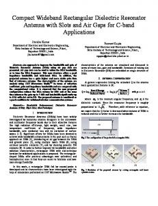
II.ANTENNA DESIGN Fig.1 shows the geometry of the four element RDRA array. Teflon of dielectric constant ( εr ) 2.1 is used as Dielectric Resonator (DR). The DR has been placed on the substrate having dielectric constant ( ε r1 ) 4.4 with 1.6 mm of thickness.
I. INTRODUCTION The Dielectric Resonator Antenna (DRA) is potentially attractive for millimeter wave applications as it has no metallic losses. DRA having numerous advantages which includes small size, light weight, low cost, and ease of excitation. It also provides wide bandwidths, low dissipation loss at high frequencies with high radiation efficiency due to the absence of conductors and surface wave losses [1]-[5]. In many cases with a single element DRA, desired specifications cannot be achieved. For example high gain, high efficiency, directional radiation pattern cannot be synthesized with a single DRA of any shape. In these applications, a DRA array with appropriate element arrangement and modified feed configurations can be used to provide desired specifications [6]-[8]. A number of excitation methods have been investigated, such as the coaxial-probe feed, aperture-coupling feed, direct microstrip line feed, coplanar waveguide feed, conformal patch with microstrip line feed and dielectric image guide feed [2]. Among the various excitation methods conformal patch with microstrip line feeding is used in the proposed RDRA array [9], [10]. In this paper, we presents a four element RDRA fed by RCP with microstrip line for wireless applications. The antenna covers the WLAN 4.9 GHz and 5 GHz bands limited by IEEE 802.11y and 802.11a/h/j/n family. It also covers the WiMAX 5.8 GHz band of IEEE 802.16d family [11]. The antenna is simulated to analyze the performance of the designed antenna array such as return loss, radiation patterns, gain and directivity. The design methodology of this DRA array is discussed and the detail results of the proposed antenna are presented in this paper.
Wr Lr L4
L3
W5
L6 L
L5
W4
L1 W2 L2
W3
W1 W
(a)
Tr
Wc Lc Lf
978-1-4673-5036-5/13/$31.00 © 2013 IEEE
(b)
671
0
-10
S11 (dB)
Lg -20
-30
W g=72 mm W g=68 mm
Wg (c)
3.5
Fig.1 (a) Front view (b) Perspective view (c) Rear view of RDRA array
The dimension of the substrate is 90×50 mm2 (W×L). The rear side of the substrate is covered with ground plane dimensioned as 72×50 mm2 (Wg×Lg). The RDRA is having resonators of square cross section of dimension 11×11 mm2 (Wr×Lr) with thickness Tr = 12 mm. The excitation mechanism adopts rectangular conformal patch of size 8×7.5 mm2 (Wc×Lc) connected to microstrip corporate feed arrangement. 50 ƺ lines and 70.5 ƺ lines are used in the microstrip feed line for impedance matching. The dimensions of the feed line are W1 = W3 = W4 = 3 mm, W2 = W5 = 1.6 mm, L1 = 14 mm, L2 = 14.8 mm, L3 = 17. 289 mm, L4 = 14 mm, L5 = 3.018, L6 = 3 mm and Lf = 2.15 mm. Proper spacing is maintained between the dielectric resonators to avoid mutual coupling. III.
RESULTS AND DISCUSSIONS
A. Parametric Study Parametric studies are carried out by comparing different designs of the RDRA array to achieve desired antenna performance.
0
4.0
4.5
5.0
5.5
6.0
6.5
7.0
7.5
Frequency(GHz)
Fig.3 Comparison of S-parameter for different Wg values
Fig.2 shows the simulated S-parameter for different RCP heights of the RDRA. By altering the height of RCP, some variation in resonant frequency has been observed. For the case of Lc = 7.5 mm we are getting a total 3.1 GHz bandwidth with S11 (dB) value less than -10 dB whereas for the other values of Lc the entire bandwidth is not covered. Another parametric study has been done by taking different width of the ground plane shown in Fig.3. By setting different width of the ground plane we can see variation in the bandwidth curve. By setting ground plane Wg = 76 mm we are getting the widest bandwidth but with a notch in between the curve. With Wg = 68 mm a notch is coming in between the bandwidth curve, but with 72 mm we are getting a whole bandwidth from 4 to 7.1 GHz. B. Gain and Directivity Characteristics Fig.4 plots the simulated gain and directivity versus frequency of the proposed DRA array, where the gain is 7.852 dB at 4.2 GHz, 9.083 dB at 5.2 GHz, 10.55 dB at 6.2 GHz and 9.568 dB at 7 GHz. It also shows directivity of 7.898 dB at 4.2 GHZ, 9.109 dB at 5.2 GHz, 10.57 dB at 6.2 GHz and 9.783 dB at 7 GHz. From the plot we can conclude that the given antenna shows very good gain and directivity values.
-10
11
10
-20
9
-30
dB
S11 ( dB)
W g=76 mm
-40
8
-40
RCP of Height 7.5 mm RCP of Height 6.5 mm RCP of Height 8.5 mm
7
G ain D irectivity
6
-50 3.5
4.0
4.5
5.0
5.5
6.0
6.5
Frequency (GHz)
Fig. 2 Comparison of S-parameter for different RCP values
7.0
7.5
3.5
4.0
4.5
5.0
5.5
6.0
F re qu en cy(G H z)
Fig.4 Gain and Directivity curves for the RDRA array
6.5
7.0
7.5
672
C. VSWR Characteistics 0 10
3.0
0 300
-10
2.5
60
-20
E field at 5.2 GHz H field at 5.2 GHz
2.0 -30
VSWR
30
330
270
90
-20
1.5
-10
240
1.0
120
0
0.5
210
10
150 180
VSWR 0.0 3.5
4.0
4.5
5.0
5.5
6.0
6.5
7.0
7.5
(b)
Frequency(GHz)
Fig.5 VSWR vs Frequency curve
0
The simulated result of the proposed RDRA array is also showing a very good voltage standing wave ratio (VSWR) over the entire frequency range. Fig.5 shows the simulated VSWR against frequency. It has been remarkable that VSWR values are less than 2 over the entire bandwidth. D. Radiation pattern characterestics The radiation pattern describes the relative strength of the radiated field in various directions from the antenna, at a fixed or constant distance. The radiation pattern is a "reception pattern" as well, since it also describes the receiving properties of the antenna. The radiation pattern is three-dimensional, but can be represented by two-dimension also. These simulated patterns are presented in a polar format. The simulated far field radiation patterns of the proposed four elements RDRA array is shown in Fig.6. It shows the simulated radiation patterns at 4.2, 5.2, 6.2 and 7 GHz. It has been observed that the E plane radiation patterns are in broadside direction against frequency and the H plane radiation patterns are omnidirectional.
10
330
30
0 300
-10
60
E field at 6.2 GHz H field at 6.2 GHz
-20 -30
270
90
-20 -10
240
120
0 210
10
150 180
(c)
0 10
330
30
0
0 10
330
0 60
-30
-20
E field at 7 GHz H field at 7 GHz 270
90
-20
E field at 4.2 GHz H field at 4.2 GHz
270
90
-20 -10
60
-20
300
-10
-30
300
-10
30
-10
240
120
0
240
120
10
210
150 180
0 10
210
150
(d)
180
(a)
Fig.6 radiation pattern of the RDRA array at (a) 4.2 (b) 5.2 (c) 6.2 and (d) 7 GHz
673
IV.
CONCLUSION
In this paper, a four element RDRA array is presented for wireless applications. The proposed DRA array consists of four dielectric resonators of same sized rectangular cross section which are excited by RCP fed connected to microstrip line in corporate feeding technique. The simulated results show the designed antenna covers the frequency range from 4 to 7.1 GHz which covers several important application bands in current wireless communication systems. References [1]
[2] [3]
[4]
[5] [6]
[7]
[8]
A. Kishk, “Dielectric Resonator Antenna, a candidate for radar application”,Proc. Of the 2003 Radar Conference, pp. 258–264, May 2003. A. Petosa, Dielectric Resonator Antenna Handbook, Artech House Publishers, 2007. A. Petosa, and A. Ittipiboon, “Dielectric resonator antennas—A historical review and the current state of the art,” IEEE Antennas and Propag. Magazine, vol.52, no. 5, pp. 91-116, Oct. 2010. K. Lu, K. W. Leung, and Y. M. Pan, “Theory and experiment of the hollow rectangular dielectric resonator antenna,” IEEE Antennas Wireless Propagat. Lett., vol.10, pp. 631-634, 2011. K. M. Luk and K. W. Leung, Dielectric Resonator Antennas. Hertfordshire, U.K.:Research Studies Press Ltd., 2002. M.S.M. Aras, M.K.A. Rahim, Z.Rasin and M.Z.A. Abdul Aziz, “An Array of Dielectric Resonator Antenna for wireless application,” IEEE International RF and Microwave Conference Proceedings, pp. 459.463, Dec 2008. G. Drossos, Z. Wu, and L. E. Davis, ‘‘Four-element planar arrays employing probe-fed cylindrical dielectric resonator antennas,’’ Microw.Opt. Technol. Lett., vol. 18, no. 5, pp. 315---319, 1998. Zhang Xiangjun; Lai Qifeng; Ma Xiaoping; , "Novel hexagon shaped dielectric resonator antenna array for wideband applications," Microwave, Antenna, Propagation and EMC
Technologies for Wireless Communications, 2009 3rd IEEE International Symposium on , vol., no., pp.639-642, 27-29 Oct. 2009. [9]
Liang X.-L., Denidni T.A and Zhang L. N, “Wideband L-Shaped dielectric resonator antenna with a Conformal inverted-trapezoidal patch feed”, IEEE Trans. Antennas Propag., vol. 57, no. 1, Jan 2009,pp. 271-274 [10] Lucia C. Y. Chu, Guha D. and Antar Y. M. M, “Conformal Strip-Fed Shaped Cylindrical Dielectric Resonator: Improved Design of a Wideband Wireless Antenna”, IEEE Antennas Wirel. Propag. Lett., vol. 8, 2009, pp 482-484. [11] Z. Abate, WiMAX RF Systems Engineering, Artech House Publishers, 2009.