IEEE Asia-Pacific Conference on Circuits and Systems, Chiangmai, Thailand, 1998. (IEEE APCCAS 98)
A FPGA-based Behavioral Control System for a Mobile Robot Angkul Kongmunvattana and Prabhas Chongstitvatana Department of Computer Engineering Chulalongkorn University Bangkok, Thailand 10330
[email protected] Tel (662) 218 6956 Fax (662) 218 6955 Abstract Th i s p a p e r d e s c r i b e s t h e d e s i g n a n d implementation of mobile robot subsumption architecture in which the computing elements of control are based on programmable FPGA devices. This paper also shows the marriage of two concepts, subsumption architecture and FPGA design. To demonstrate the effectiveness of this approach a mobile robot control chip which performs the foraging behavior of an ant has been designed. The design has been implemented using Xilinx 4003. An instance of behavior model, homing behavior, is discussed and formulated into a logical design. From the logical design we use the schematic capture and supporting software to simulate, refine, and synthesize the logic gates. The gate list is finally mapped onto the FPGA devices using Xilinx synthesis tools. Results indicate that the control chip performs the homing behavior correctly. 1. Introduction The emergence of reconfigurable Field Programmable Gate Arrays (FPGA) has given rise to a new platform of complete mobile robot control system. With FPGA devices, the designer may tailor the design to fit the requirement of control system functions for a mobile robot. General-purpose computer can provide acceptable performance for mobile robot control when the tasks are not too complex. Because the single processor system cannot guarantee real-time response for any task when the complexity of the tasks have been increased [1]. A FPGA-based control system is designed to solve the problem of parallel tasks achieving control which occurs on single processor machine. The parallel scheme has been applied toward this design without any problem of performance and the availability of I/O channels. A FPGA-based robot control chip improves upon the single processor computer in the following areas: • Scalability of the control system, FPGA chips can integrate and still perform the previous defined tasks efficiently, especially when more tasks achieving are required. • Increase the availability of I/O channels.
• Directly map the logical designed to the computing elements in FPGA devices. • Support parallel design scheme which leads itself to guarantee the control response time, real-time. • Low power consumption compared to the single processor computer or even the micro-controller. • Support the logical design of the non-Von Neumann computational models. This is important because our task achieving is always based on the behavior of an insect and the behavior control models of an insect are closer to the non-Von Neumann models [2]. • Simplify the task achieving of each part and easily verify the correctness of the logical design modules. This help the designer to work in more comfortable environment. In 1985, Brooks introduced the subsumption architecture, the first and best-known example of what has come to be known as the behavior-control paradigm [3]. Behavior control is based on decomposing the problem of autonomous control by task rather than by function. Behavior control advocates the construction of special-purpose task-achieving modules that are connected directly to sensors and actuators and operate in parallel. These modules are usually called Behaviors. A number of approaches to behavior control have emerged since Brooks introduced the approach e.g. [4, 5, 6, 7, 8, 9], including cooperation of multi robots [10]. 2. The Behavioral Control System The key idea of levels of task achieving behaviors is that we can design layers of control system corresponding to interaction of each Behavior. It is also simple to add a new layer to an existing set to make the robot control system more competence. We start by designing a complete robot control system which achieves a simple task. It is debugged thoroughly and then more Behaviors and new layers of control are added to achieve a more complex behavior. There are two significant advantages when we implement behavior control with FPGA devices. First, because Behaviors operate in parallel rather than in
IEEE Asia-Pacific Conference on Circuits and Systems, Chiangmai, Thailand, 1998. (IEEE APCCAS 98) serial, fast Behaviors need not be delayed by slower ones, allowing the robot to respond to contingencies in real time. Due to the nature of parallelism, we can make the control system arbitrarily large without saturating any resource. Constraints on the number of I/O pin are also relaxed because Xilinx chip has a large number of I/O channels compared with the communication ports available on computer [11]. Also, if we want more behaviors, we simply add more chips. This is why it is suitable to use FPGA devices as a behavioral control system. Second, because Behaviors are task-specific rather than general-purpose, Behavior designer can take advantage of the structure of the task in order to simplify the Behavior. This is the underlying reason why Behaviors tend to be simple. The modularity and simplicity of task-specification in Behavior design lead themselves naturally to the logical design of hardware. This is important because we can map the logical design to the reconfigurable elements in the FPGA devices easily. 2.1 The Ants Navigation This work demonstrates the efficiency of chip design and implementation based on the following behavior of an ant. Ants have to find food like other lives. But once an ant leaves the nest, it has the problem of finding its way back. Ants are believed to do this in two ways, with visual clues or with chemical clues [12]. Ants that use visual clues, such as a prominent part of the landscape like a tree or a rock, or the polarized light of the sun, tend to travel in straight lines to and from the nest. Other ants of the same colony will travel parallel to it but not in a line behind it. We use a simulation to demonstrate the strategy of homing navigation of an ant that uses the sun light as a visual clue. The simulation engine performs as a control system for the foraging behavior of a mobile robot. We define the simulation function into three states : reset, wandering, and homing. After the reset state the robot rotates and stops when reaches the reference angle of the simulation, parallel with the sun light. Then the part of wandering control begins to work. The wandering control generates a random vector for the robot to follow at each step. This random move is repeated until the homing signal occurs then the robot enters the homing state. A homing vector from the present robot's coordinate to the starting point is generated. The robot "goes home" by following the homing vector. The robot moves half of the distance and rechecks its direction. If it recognizes that the direction is wrong the robot will generate a new homing vector which corresponds to the
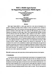
present coordinate. This iteration stops when the robot's coordinate is close to the starting point of random walk. 2.2 The Design of Subsumption Architecture The subsumption architecture of foraging behavior is shown in Figure 1. The design is based on two input sensors : photo sensors and wheel counters sensors and the outputs are the signal to two motors. The control system design follows a bottom-up design methodology. The control system is organized into layers according to the level of abstraction. Each layer interfaces to the previous layers below it by an inhibit or suppress signal that plays the role of actuators. As one goes up in the hierarchy, the actuators control the robot at higher levels of abstraction, more complex task-achieving behaviors. The first layer consists of a single module for coordinating the photo sensors and motors. This layer performs a random rotation. The second layer consists of a single module which coordinates the wheel counter sensors and motors. This layer controls the robot to move a distance specified by a random displacement. The top layer controls the robot to go back to its home when the homing signal has occurred. It consists of two modules, one module builds a present homing vector. Another module is a part of the motor control which performs rotation and straight line motions corresponded to the homing vector generated by the first module. 3. Experiment and Results The logical design of foraging behavior is obtained from the subsumption architecture as shown in Figure 2. The first and second layers are for the random walk whereas the top layer is for the homing navigation. At the first layer, a magnitude comparator compares the angle of the light acquired from the photo sensors with an angle generated from a random number generator. The comparison result is used to enable the rotation of only the right until the angle of the light source matches the randomly generated angle. Then the control activates the second layer. At this layer, the wheel counter starts counting the number of wheel rotations sensed from the wheel counter sensors (which represents the robot displacement). Both wheels keeps rotating until the displacement in the counter matches a randomly generated displacement. This is accomplished by using the output of the comparator to enable the rotation of both the left and the right wheels. At the top layer which takes care of the homing behavior, two more counters, X-coordinate and Y-coordinate, along with two magnitude comparators are used to keep track of the robot positions. The values added to both counters come from an external ROM look up table which keeps
IEEE Asia-Pacific Conference on Circuits and Systems, Chiangmai, Thailand, 1998. (IEEE APCCAS 98) the magnitudes of unit vector in all 360 degrees of angles. The outputs of both comparators enable the wheels to rotate until the mobile robot reaches the home position using the homing navigation strategy mentioned in Section 2.1. The chip's functionality was verified by using the ViewLogic simulation tools, ViewSim and ViewTrace [13, 14]. The input data consisting of the current angle and the wheel count from sensors are randomly generated by another program. The output data are the left and right wheel control signal. We ran the simulation a hundred times with different input data and verified that the final homing navigation always succeed. 4. Summary Th i s p a p e r d e s c r i b e s t h e d e s i g n a n d implementation of a control chip for a simple mobile robot foraging behavior using a FPGA custom computing platform. The homing behavior is adopted from the behavior of an ant navigation. This design may be described as a mapping from the input sensors to the actuators which control the robot motions. This control system has been designed for real-time control based on subsumption architecture. It is shown that FPGA can be configured to implement the design successfully. Acknowledgement National Science and Technology Development Agency of Thailand has generously funded the FPGA design tools and the Xilinx development system without which this work will not be possible. We would like to thank Somchai Prasitjutrakul for his help in setting up the design system and for his expert advice on FPGA. References [1] R. A. Brooks, "A Hardware Retargetable Distributed Layered Architecture for Mobile Robot Control," Proc. of IEEE International Conference on Robotics and Automation, NC, pp. 106-110, 1987. [2] R. A. Brooks, "Intelligence Without Reason," in Proc. International Joint Conference on AI, Sydney, Australia, August, 1991. [3] R. A. Brooks, "A Robust Layered Control System for A Mobile Robot," IEEE Journal of Robotics and Automation, RA-2, pp. 14-23, April, 1986. [4] R. A. Brooks, "A Robot that Walks; Emergent Behaviors from a Carefully Evolved Network," Neural Computation 1:2, pp. 253-262, 1989.
[5] J. H. Connell, "Creature Design with the Subsumption Architecture", Proceeding of IJCAI, pp. 1124-1126, 1987. [6] E. Gat, R. Desai, R. Ielev, J. Loch, and D. P. Miller, "Behavior Control for Robotic Exploration of Planetary Surfaces," IEEE Trans. on Robotics and Automation, Vol. 10, No. 4, pp. 490-503, August, 1994. [7] T. Oka, K. Takeda, M. Inaba and H. Inoue, "Designing Asynchronous Parallel Process Networks for Desirable Autonomous Robot Behaviors", in Proc. of IEEE/RSJ Int. Conf. on Intelligent Robots and Systems, Vol. 1, pp. 178185, 1996. [8] J. K. Rosenblatt and D. W. Payton, "A FineGrained Alternative to the Subsumption Architecture for Mobile Robot Control," in Proc. of International Joint Conference on Neural Network, Washingtion, D.C. June, 1989. [9] R. G. Simmons, "Structured Control for Autonomous Robots," IEEE Trans. on Robotics and Automation, Vol. 10, No. 1, pp. 34-43, February, 1994. [10] Z. Wang, E. Nakano, T. Matsukawa, "Realizing Cooperative Object Manipulation using Multiple Behavior-based Robots", in Proc. of IEEE/RSJ Int. Conf. on Intelligent Robots and Systems, Vol. 1, pp. 1310-317, 1996. [11] Xilinx, Inc., The Development System Reference Guide, San Jose, CA, 1994. [12] D. W. Stokes, A Guide to Observing Insect Lives, Little, Brown and Company Limited, Canada, 1985. [13] Viewlogic System, Inc., ViewSim Reference Manual, Marlboro, MA, 1993. [14] Viewlogic System, Inc., ViewTrace User's Guide, Marlboro, MA, 1993.
IEEE Asia-Pacific Conference on Circuits and Systems, Chiangmai, Thailand, 1998. (IEEE APCCAS 98)
Homing Path Planning
Walk Home Homing Control Layer
Wheel Counter Sensors
Random Walk
S
Random Walk Control Layer Photo Sensors
Random Rotation
S
Wheel Control System
Random Rotation Control Layer Motors Figure 1. Subsumption architecture of Foraging Bahavior
External ROM
Homing Signal
X-Coordinate Counter
Magnetude Comparator
Y-Coordinate Counter
Magnetude Comparator
Homing Control Layer Wheel Counter Sensor
Wheel Counter
Random Angle Generator Random Walk Control Layer
Magnetude Comparator
Photo Sensors Magnetude Comparator Random Angle Generator Random Rotate Control Layer
ROM
ROM
MUX Motors
Figure 2. Logical design of the behavioral control chip