work, there have been a number of surgical simulators and ..... This issue requires further study, since simulators for train- ..... (Eds.), IOS Press, 2004, pp.
A Fracture Mechanics Approach to Haptic Synthesis of Tissue Cutting with Scissors Mohsen Mahvash and Allison M. Okamura Department of Mechanical Engineering Engineering Research Center for Computer-Integrated Surgical Systems and Technology The Johns Hopkins University, USA E-mail: {mahvash, aokamura}@jhu.edu
Abstract An analytical model for cutting of a plate of material with a pair of scissors is presented in terms of concepts of contact and fracture mechanics. The forces of contact between the blade of the scissors and the plate are expressed by a nonlinear function of deflection at the crack front multiplied by the length of the contact region between the blade and the plate. The cutting model captures the combined effect of multiple fracture modes. The level of deflection that causes fracture is obtained using an energy approach. The cutting model predicts that, during fracture, force and torque responses of the scissors depend on the toughness and geometry of the plate, but do not depend on the stiffness of the plate. The model is used for haptic synthesis of interaction between a pair of scissors and a virtual plate. An implementation of the model is presented for the case of surgical scissors in contact with skin. The simulation results are compared to previous experimental data, demonstrating the realism of the cutting model behavior. This haptic rendering technique is computationally efficient and can be applied to real-time simulation.
1
Introduction
Scissors are one of the oldest and most ubiquitous surgical instruments. Many types of scissors are used to perform various tasks in open and laparoscopic surgical procedures [14]. The feeling of forces between the fingers during cutting with scissors can provide the surgeon with valuable information about tissue properties and tool-tissue interaction states. For example, different tissues have distinct cutting “signatures” [8]. Also, the scissor handle forces can reflect whether the tissue is actually being cut or if it is slipping out from between the blades. Recent efforts have addressed realistic surgical simulators that allow tissue separation due to single-blade and scissors cutting, and many of these provide resolved force feedback to the operator. However, none of the work from
other groups provide the “between-the-fingers” forces essential to realistic display of cutting with scissors. Chanthasopeephan, et al. [7] and Mahvash and Hayward [11] studied cutting with a single blade. Outside our previous work, there have been a number of surgical simulators and mesh separation algorithms that handle cutting, e.g. [6, 15] but they may not provide accurate force feedback at the end of a cutting tool due to their linear deformation models and coarse meshes [11]. This research builds on our previous work to measure and render scissor cutting of various materials. Greenish, et al. acquired data for cutting various materials with scissors [8], and these data were used to develop realistic virtual displays of cutting using a “haptic recording” approach [3]. Perceptual experiments were performed that demonstrated the realism of this approach [13], although there is no ability to change the feedback based on the context of the user’s motion. Weiss [17] integrated cutting with a deformable tissue plate based on a mass-spring-damper model and a deflection threshold for fracture. The parameters of that model were tuned manually. None of this previous work has developed an analytical approach, which is required for context-dependent and computationallyor memory-efficient haptic rendering. The analytical approach taken in this paper demonstrates that contact forces depend on parameters that have not been measured in previous scissor cutting experiments with real materials. We emphasize that this analytical approach is a physicallybased approach that satisfies the law of conservation of energy and ensures that the simulation results depend on measurable parameters and not on arbitrary choices. Our analytical approach builds on that of [11], in which the authors developed a fracture mechanics approach for haptic rendering of cutting that applies to a single blade or needle. The analytical model we present here describes the contact of scissors with a plate of material. This model makes some assumptions (described in Section 2) so that the parameters of the model can be derived from a few measurements. An energy approach from fracture mechanics defines when the object will be cut. The model predicts
that, during fracture, torque and force responses depend on the fracture toughness and thickness of the plate, but not on the force-deflection curve and the stiffness of the plate. This result is supported by the fact that scissors are used as a tester for measuring fracture toughness of the biological materials [5]. While the models described in this paper apply to cutting a wide range of materials, our particular interest is the interaction between scissors and soft tissues. The remainder of the paper is organized as follows: Section 2 describes an analytical model for cutting of a plate of material with scissors. Section 3 explains the most likely trajectory for a cutting interaction and an algorithm for synthesizing that trajectory. An implementation of the algorithm and comparison with experimental data is described in Section 4. Finally, Section 5 provides conclusions and areas for future work.
2
δc
θ
x p xc
θ
x
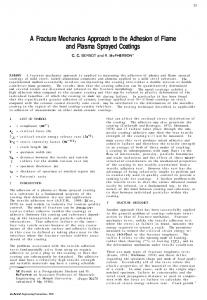
Figure 1: Cutting of a thin plate of material with a pair of scissors. The scissors’ pivot only moves along the x direction. The lower blade of the scissors does not have any angular motion. dx
Scissor-Material Interaction Model
h
Figure 1 shows cutting of a plate of material with a pair of scissors. The plate rests along the edge of the lower blade of the scissors. Only the upper blade has angular motion during interaction, and the pivot of the scissors can only move on the surface of the plate along a straight line parallel to an axis denoted by x. xp defines the location of the pivot and θ defines the opening angle of the scissors. Cutting involves two distinct phenomena in the plate: deformation and fracture. Deformation is caused by the scissors when the sharp edges of the blades compress and/or deflect the plate. The fracture occurs at the front of a crack developed in the plate along x. xc defines the location of the crack front and δc the length of deflection or compression at the crack front. It is assumed that the plate of material is initially free from residual stress and external pre-loading and purely elastic nonlinear deformation occurs in the entire plate, except in a small region around the crack front where elastic-plastic fracture occurs. The component of force applied to the upper blade in the direction normal to the blade edge is needed for haptic simulation. This component is defined as fn , and it is calculated during two distinct regimes by a contact model (Section 2.1) and a fracture model (Section 2.2).
2.1
fn
dd
q
dl
D
dc
q w 2
xp
xc x
Figure 2: Contact of a pair of scissors with a thin plate of material. The deflected part of the plate is shown by a lighter color. Deflection δc is related to θ and xc by defining tan θ for the triangle marked by dashed lines.
In this analysis, g(θ, δc ) does not consider the effect of a change in crack length on the normal force. During contact, as shown in Figure 2, δc can be related to the position and angle of the scissors by tan θ =
Contact Model
∆ − δc + h + w/2 xc − xp
(2)
where h is the thickness of plate, w is the width of the w blades and ∆ = 2cosθ . For small θ, ∆ ' w/2, therefore the above equation concludes that
The static state of deformation in an elastic object under load generally depends on the forces that are applied to the boundary of the object [10]. When a rigid tool contacts a deformable object, the position and orientation of the tool with respect to the object uniquely defines the forces applied to the object. Therefore, the resultant force applied by the tool can be expressed by a nonlinear function of the position and orientation of the tool. We apply the above analysis to the scissor-plate interaction of Figure 1 to calculate fn as a nonlinear function of θ and δc : fn = g(θ, δc ). (1)
δc = (h + w) − (xc − xp ) tan θ.
(3)
To study how g varies with respect to θ, we assume that the forces applied to an infinitesimal element of the plate located inside the contact area only depend on the deflection of the element itself (Figure 2). dfn = e(δ)dl,
(4)
where e(δ) is a nonlinear function. Then, fn can be ob2
tained by Z
L
e(δ)dl,
fn =
t
(5)
0
δ cut
δe = h + w − R sin θ,
f (δc ) − f (δe ) f (δc ) − f (δe ) = L sin θ δc
(xc − xp )(f (δc ) − f (δe )) . sin θ
θ + dθ
h
(7)
(8)
dA
f (δc ) − f (δe ) dθ. sin θ (13) The work of fracture for separating an area of size dA can be obtained by
(9)
dWe = (f (δc )−f (δe )) dxp −(xc −xp )
dWA = Jc dA,
(14)
where Jc is the toughness of the material [2, 11]. If other forms of energy loss during cutting, such as burring and plastic flow, have uniform geometries along the crack, the work of fracture would still be proportional to the crack area. However, the fracture toughness should be replaced by a greater value that represents the energy loss per unit area for the particular interaction occurring. We assume that fracture occurs at any location on the plate whose deflection reaches to a threshold δcut . This way, as shown in Figure 3, dA can be obtained by
Fracture Model
Figure 3 shows the state of the plate and the scissors at times t and t + dt of the cutting interaction. If fracture occurs during time dt, the crack front, xc , will move to xc + dxc . The fracture separates a rectangular area of material with a length of dxc and width of w. Fracture will occur in the plate if the energy created by the scissors is enough to deform and separate the plate [2]: (11)
dA = h dxc .
(15)
∂xc ∂xc dxp + dθ. ∂xp ∂θ
(16)
dxc is calculated by
where dWe is the external work applied by the scissors, dU is the change in elastic potential energy stored in the object and dWA is the irreversible work of fracture. If we assume quasistatic operation (i.e., the inertia terms are ignored), the external work dWe can be calculated by dWe = −fx dxp − τ dθ,
xc + dxc
where fx and τ are the force and torques applied to the scissors by the plate. Substituting Equations 9 and 10 into Equation 12 gives:
f (δc ) can be a piece-wise polynomial synthesized from measurement data.
dWe ≥ dU + dWA ,
x p + dx p
θ + dθ
Figure 3: Fracture of a thin plate of material due to contact with a pair of scissors during time dt. The top part of the figure shows the states of the plate and scissors at time t, and the bottom part shows those states at time t + dt when fracture has just occurred.The marked rectangle shows the new crack area created during time dt.
The force applied to the pivot of the scissor along the direction of the movement of the pivot, fx , can be obtained by fx = −fn sin θ = −(f (δc ) − f (δe )) (10)
2.2
δ cut
t + dt
When the crack front is not near the end of the blade, the deflection at the end of the contact region is zero. Thus, f (δe ) = f (0) = 0. Assuming that the length of contact line is much smaller than the distance between the crack front and the position of the pivot, L � (xc − xp ) the torque caused by fn is τ = (xc − xp )fn =
xc
xp
where R is the total length of the blade from the pivot to end of the blade. Rδ If we define f (δ) ≡ 0 e(η)dη, the normal force can be obtained by fn =
θ
θ
where L is the length of the contact area. dδ Figure 2 shows that dl = sinθ . Thus, Equation 1 can be written as R δc e(δ)dδ fn = δe , (6) sin θ where δe is the deflection at the end of contact region. δe is calculated by
dxc =
Assuming that δcut does not depend on the angle of the scissor blades or the position of the crack front, the partial
(12) 3
derivatives in Equation 3 are: ∂xc ∂xp ∂xc ∂θ
=
1
= −2
f (δ c )
(17) xc − xp sin 2θ
3
(18)
2
The work of fracture is obtained from Equations 14– 18: � � xc − xp dWA = Jc h dxp − 2 dθ . (19) sin 2θ
δc
During fracture, dU is related to dθ and to dxp by ∂U ∂U dU = dθ. dxp + ∂xp ∂θ
3
(23)
Cutting Interaction Sequences
(25)
Figure 4 shows the most likely force-deflection trajectory for a cutting interaction between a pair of sharp scissors and a plate. The trajectory starts at a point where the top blade is not yet in contact with the plate, so the force applied to the top blade is zero. The blade deforms the region of the plate around the crack front xc , such that the level of deflection at the crack front is δc . If the contact is sharp enough, fracture starts when δc reaches δcut and continues as long as the pivot of the scissors moves forward or the scissors are being closed. Equation 3 concludes that, during fracture, the crack front should move as
(26)
xc = xp + (h + w − δcut ) cot θ
Depending on how the scissors move (a possible combination of angular and forward motion), fracture may occur when one or both of the following conditions are satisfied:
For a small θ, cos θ ' 1, so the above conditions become a single condition:
(30)
in order to maintain δc = δcut . When the scissors are either opened or retreated, the fracture stops and the deformation at a new crack front relaxes. The other, less likely, trajectory for a cutting interaction is the case when the contact is not sharp enough, and consequently fracture does not start at δc = δcut . In this case, the deformation of the plate continues until the plate is damaged. We do not simulate that case in this paper. This issue requires further study, since simulators for training should teach the user how to manipulate the scissors in
(27)
Substituting the above into Equations 3 and 10 finds the force and torque on the scissors during fracture:
fx
(29)
The above equation calculates the deflection from which fracture occurs.
(f (δc ) − f (δe )) dθ sin θ
(xc − xp )Jc h sin θ = −fn sin θ = −Jc h.
0
f (δcut ) = Jc h.
(f (δc ) − f (δe ) − Jc h) dxp (24) � � xc − xp Jc − f (δc ) − f (δe ) − dθ ≥ 0 sin θ cos θ
=
start
The force and torque during fracture are independent of the force-deflection curve, and consequently the stiffness of the plate. If the crack front is not near the end of the blade, so that δe = 0, Equation 27 is written as:
or
τ
4
Figure 4: The most likely trajectory for force-deflection at the crack front. During fracture, the crack front moves along x. The trajectory marked with a dashed line show a less likely trajectory for cutting.
By substituting Equations 13, 19 and 22 into Equation 12, the condition for fracture is obtained as
f (δcut ) − f (δe ) = Jc h.
xc
(20)
If we ignore the change in elastic energy due to the change of opening angle of the scissors during fracture, i.e. ∂U ∂θ = 0, we will have dU = 0. (22)
f (δcut ) − f (δe ) ≥ Jc h Jc h f (δcut ) − f (δe ) ≥ cos θ
1
contact
When fracture occurs due to the movement of the pivot alone, the deformation pattern around the crack front translates, but does not change shape. Therefore, the potential elastic energy stored in the plate does not change during fracture: ∂U = 0. (21) ∂xp
(f (δc ) − f (δe )) dxp − (xc − xp ) � � 2(xc − xp ) ≥ Jc hdxp − . sin 2θ
δ cut
(28)
4
order to create a sharp contact for a predictable, clean cut that minimizes tissue damage. The following algorithm provides haptic rendering of sharp cutting with a pair of scissors. This algorithm should be repeated at a high rate in order to provide passive interaction [4, 12]. //Algorithm for cutting with scissors //θ and xp measured, xc internal state sharpContact ← true δc ← (h + w) − (xc − xp ) tan θ δe ← (h + w) − R sin θ if δe < 0 δe = 0 if δc < 0 ∨ δe > δc //no contact δc ← 0 τ ←0 fx ← 0 exit fi if δcut < δc if sharpContact δc ← δcut //fracture xc ← xp + (h + w − δcut ) cot θ fi fi (xc − xp )(f (δc ) − f (δe )) τ← sin θ fx ← −(f (δc ) − f (δe ))
4
Figure 5: Two-degree-of-freedom haptic scissors.
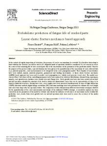
that, in order to rigorously determine all the parameters in our model, new experimental data is required. This is a topic for future work.) As torque-angle curve of Figure 6c shows, the blade starts to contact with the skin at Point 1. From Point 1 to Point 2, the skin deforms without any fracture. Fracture starts at Point 2 and continues until Point 4. At Point 3, the cutting point nears the end of the scissor blades, and the force drops. The torque responses during fracture depended on the fracture toughness of the skin, the thickness of the skin, and the size and geometry of the scissors, but not on the force-deflection curve. This is an interesting result for the specific case examined (cutting skin with Mayo scissors), but further investigation is needed to confirm this with different materials and scissor types. Comparing the synthesized results with measured data confirmed the general correctness of the cutting model behavior. However, the simulated torque-angle curve has much steeper slopes than the experimental data at small angles. This might be due to one of following assumptions made during modelling: (1) The scissor blades are assume to have straight edges, and (2) The level of deflection at which fracture occurs is considered to be a constant, independent of the angle of the scissors. The torque-angle curve of Figure 6c shows non-smooth behavior between Points 2 and 3. This is due to nonsmooth angular movement of the scissor blade, causing switching between deformation and fracture. Such nonsmooth motion will occur for any human user. These irregularities tend towards unstable large oscillations near Point 3, where the torque-angle curve becomes very steep. These oscillations can be prevented by increasing the rate of simulation, as long as the effects of other uncertainties of the control loop, such as quantization noise and dynamics of the actuators and transmission cable, are not dominant [1, 4, 12]. We have yet not conducted a thorough human study to determine the effectiveness of our haptic simulation. How-
Implementation
The model and algorithm explained in Sections 2 and 3 were implemented on a computer to simulate cutting with a pair of scissors. The forces were rendered by the “haptic scissors,” a haptic device developed in our laboratory (Figure 5) [13]. The haptic scissors can render forces in two degrees of freedom: translational and rotational. The cutting algorithm is updated at 1 kHz by a thread run under Windows 2000. The user can set the force-deflection curve of the normal contact with a piece-wise polynomial, the toughness of the material, and the sizes of the plate and the scissors. Figures 6a, 6b, and 6c show the torque and angle responses of the haptic scissors when a layer of virtual skin is cut. In this example data, the user only closed and opened the scissors, avoiding moving the pivot. The virtual skin parameters using in this simulation had been selected by qualitative observation of tissue-cutting data for cutting of sheep skin with Mayo scissors (from Greenish and Hayward [13]). Figure 6d shows the measured torque-angle curve for cutting of sheep skin printed from [8]. (We note 5
(b)
(a)
25
45 40
20
35
t [N-m]
q [deg]
30 25 20
15 10
15 10
5
5 0
0
2
4
6
8
10
0
12
0
2
4
(c)
10
12
30 25
Force Applied [N]
25
t [N-m]
8
(d)
30
3
20 15 10 5 0
6
t [sec]
t [sec]
0
4 5
2 1 10
15
20
25
30
35
20 15 10 5 0 -5
0 40
0
5
10
15
20
25
30
35
40
q [deg]
q [deg]
Figure 6: Comparing simulated and measured responses of cutting of a layer of skin with scissors: (a) Angle-time response of the simulation, (b) Torque-time response of the simulation, (c) Torque-angle curve of the simulation, and (d) Torqueangle curve measured for cutting of a layer of sheep skin (reprinted from [8]). ever, we personally observed that the switching between deformation and fracture causes the realistic feeling of cutting of a homogenous material. We also observed that the larger oscillations, although nearly unstable, did not feel unusual. This might be due to the increase in the number of switching cycles, causing the perception of cutting an inhomogeneous material. The response of the simulator during switching between deformation and fracture should have an important role in cutting. Therefore, a model that represents more physical details of the switching regime may create a more realistic feeling of cutting. This will require more detailed experimental data from cutting real tissue than are currently available.
5
of contact between the top blade of a pair of scissors and a thin plate of material was modelled by a nonlinear function of the deflection at the crack front multiplied by the length of the contact region. The deflection function can be expressed by a piece-wise polynomial whose parameters can be identified from measurement data. Cutting of the plate has been considered as a fracture that separates any parts of the plate that are deflected larger than a minimum deflection. An energy analysis was described that calculates the minimum level of deflection that could cause fracture. The energy approach showed that the force and torque response of interaction does not depend on the force-deflection curve at the crack front. A haptic rendering algorithm was derived from the contact and fracture models that renders the most probable trajectory for cutting. An implementation of the model was explained and the results were compared with measured data for cutting with a pair of scissors.
Conclusion and Future Work
Cutting with a pair of scissors was defined in terms of concepts from contact and fracture mechanics. The force
More experiments should be performed to evaluate the 6
[5] Darvell B. W., Lee P.K.D., Yuen T.D.B., and Lucas P. W., ”A portable fracture toughness tester for biological materials,” Meas. Sci. Technol., 1996, 7:954-962.
model and the effects of applied approximations. It should be investigated if fracture always starts at a certain level of deflection that does not depend on the opening angle of the scissors. That is, more experimental data is needed to explore whether the toughness, size and location of the plate are sufficient to approximate the torque-angle relationship of the scissors during fracture in general. Pre-loading and residual stress significantly affects cutting of biological tissues. Such tissues commonly have a so-called J-shape stress-strain curve [2, 16]. For a J-shape material, the change of stress is very smooth for a range of strain at the beginning of deformation, but later the stressstrain curve experiences a large slope. Pre-deformation can bring the state of deformation in a biological material to the large slope region, where a small deflection caused by a cutting tool can generate a level of force high enough to create fracture. The effect of pre-loading could be identified using experimental data. The force-deflection curves for tool contact with biological materials also depend on the rate of interaction, due to the viscous properties of these materials. The effect of viscosity can be considered by adding dδ/dt as a new variable to the function that calculates the normal force. Viscosity may also affect the toughness of the material, such that increasing the rate of cutting decreases the level of deflection and force that causes fracture [2, 9]. The contact situations that make a sharp contact more likely should be investigated in order to create a highfidelity haptic simulator for training.
[6] Delingette, H., Cotin, S., Ayache, N., ”A hybrid elastic model allowing real-time cutting, deformations and force-feedback for surgery training and simulation,” Computer Animation Proceedings, 1999, pp. 70-81. [7] Chanthasopeephan, T., Desai, J. P., and Lau, A., ”Measuring Forces in Liver Cutting: New Equipment and Experimental Results,” Annals of Biomedical Engineering, 31(11), 2003, pp. 1372-1382. [8] Greenish, S., Hayward V., Steffen T., Chial V., and Okamura A. M., ”Measurement, Analysis and Display of Haptic Signals During Surgical Cutting”, Presence, 11(6), 2002, pp. 626-651. [9] Heverly M., Dupont P., and Tridman J., ”Trajectory Optimization for Dynamic Needle Insertion. Proceedings of the IEEE International Conference on Robotics and Automation, 2005, Submitted. [10] Johnson, K. L., Contact mechanics. Cambridge University Press, 1987. [11] Mahvash M., and Hayward V., ”Haptic Rendering of Cutting: A Fracture Mechanics Approach,” Haptics-e (www.haptics-e.org), 2(3), 2001. [12] Mahvash M., and Hayward V., ”Passivity-Based High-Fidelity Haptic Rendering of Contact,” Proc. IEEE Int. Conf. Robot. Automat., 2003, pp. 37223728.
Acknowledgements The authors thank Josh Wainer for his help in setting up the haptic scissors. This work was supported in part by the National Science Foundation Grant No. EIA-0312551, National Institutes of Health Grant No. R01-EB002004, and Whitaker Foundation Grant No. RG-02-911.
[13] Okamura A. M., Webster R. J., Nolin J. T., Johnson K. W., and Jafry H., ”The Haptic Scissors: Cutting in Virtual Environments,” IEEE International Conference on Robotics and Automation, 2003, pp. 828833.
References
[14] Qayumi A. K., Basic Surgical Techniques – An Illustrated Manual. Q & Q Publications, Vancouver, Canada, 2001, (http://www.surgicaltechniques.com).
[1] Abbott J. J., and Okamura A. M., ”A Sufficient Condition for Virtual Wall Passivity with Quantization Effects.” ASME IMECE, Aneheim, California, 2004.
[15] Song, G. J., and Reddy, N. P., ”Tissue cutting in virtual environments,” In Interactive Technology and New Paradigm for Healthcare, Satava, R. M., Morgan, K., Sieburg, H. B., Mattheus, R., and Christensen, J. P. (Eds.), Studies in Health Technology and Informatics, Chap. 54. IOS Press, 1995.
[2] Atkins A. G., and Mai Y-W., Elastic and plastic fracture: metals, polymers, ceramics, composites, biological materials, Chichester : Ellis Halsted Press, 1985. [3] Chial V., Greenish S., and Okamura A. M., ”On the Display of Haptic Recordings for Cutting Biological Tissues,” 10th International Symposium on Haptic Interfaces for Virtual Environment and Teleoperator Systems, 2002, pp. 80-87.
[16] Vincent, F. V. J., Structural biomaterials, Princeton University Press, 1991. [17] Weiss, D., and Okamura A. M. “Haptic Rendering of Tissue Cutting with Scissors in a Virtual Environment,” Medicine Meets Virtual Reality 12, J.D. Westwood, et al. (Eds.), IOS Press, 2004, pp. 407-409.
[4] Colgate, J. E., and Schenkel, G.G., ”Passivity of a Class of Sampled- Data Systems: Application to Haptic Interfaces,” Journal of Robotic Systems. 1997, 14(1):3747. 7