the deployment of multiple autonomous robots in an unstructured and unknown ..... The kinematics of the nonholonomic i-robot are given by i i i i i i i i v y v x Ï=θ.
A Framework and Architecture for Multirobot Coordination1 R. Alur, A. Das, J. Esposito, R. Fierro, G. Grudic, Y. Hur, V. Kumar, I. Lee, J. Ostrowski, G. Pappas, B. Southall, J. Spletzer, and C. J. Taylor GRASP Laboratory and SDRL Laboratory. University of Pennsylvania Philadelphia, USA {mars, hybrid}@grasp.cis.upenn.edu
Abstract: In this paper, we present a framework and the software architecture for the deployment of multiple autonomous robots in an unstructured and unknown environment with applications ranging from scouting and reconnaissance, to search and rescue and manipulation tasks. Our software framework provides the methodology and the tools that enable robots to exhibit deliberative and reactive behaviors in autonomous operation, to be reprogrammed by a human operator at run-time, and to learn and adapt to unstructured, dynamic environments and new tasks, while providing performance guarantees. We demonstrate the algorithms and software on an experimental testbed that involves a team of car-like robots using a single omnidirectional camera as a sensor without explicit use of odometry.
1. Introduction It has long been recognized that there are several tasks that can be performed more efficiently and robustly using multiple robots [1]-[4]. In fact, there is extensive literature on robot control and the coordination of multiple robots. Our goal, in this paper, is to describe a set of software tools that allows the development of controllers and estimators for multirobot coordination. The tools consist of a framework for developing software components, architecture for control and estimation modules, and a set of decentralized control, planning and sensing algorithms. Our software framework divides the overall multi-robot control task into a set of modes or behaviors, which may be executed either sequentially or in parallel. Modes can consist of high-level behaviors such as planning a path to a goal position, as well as low-level tasks such as obstacle avoidance. We use a high-level language to formally describe how and when transitions between these modes are to take place in order to achieve a set of global objectives. Finally, because it is difficult to predict exactly under what conditions switching between modes should occur, we parameterize mode boundary transitions within each robot’s information space and use reinforcement reward to obtain locally optimal mode boundary locations. Thus the multirobot system can learn to continually improve overall performance through interaction with the environment, without human intervention. 1
This research was supported in part by DARPA ITO MARS 130-1303-4-534328-xxxx-2000-0000.
2. Motivation There is extensive literature on the control of robot manipulators or mobile robots in structured environments, and robot control is a well understood problem area. However, traditional control theory mostly enables the design of controllers in a single mode of operation, in which the task and the model of the system are fixed. When operating in unstructured or dynamic environments with many different sources of uncertainty, it is very difficult if not impossible to design controllers that will guarantee performance even in a local sense. A similar problem exists in developing estimators in the context of sensing. If one views planning as an extension of control, and mapping as an extension of estimation, similar problems exist at higher levels of control and coordination. In contrast, we also know that it is relatively easy to design reactive controllers or behaviors that react to simple stimuli or commands from the environment. This is the basis for the subsumption architecture [5] and the paradigm for behavior-based robotics [6]. While control and estimation theory allows us to model each behavior as a dynamical system, it does not give us the tools to model switches in behavior or the hierarchy that might be inherent in the switching behavior, or to predict the global performance of the system. Our goal in this paper is to present the software tools that are at the core of the development of intelligent robotic systems. Specifically, we describe an architecture and a high-level language, CHARON, with formal semantics, that can be used to describe multiagent, networked robotic systems with multiple control and estimation modes, and discrete communication protocols in a principled way. The architecture allows the development of complex multirobot behavior via hierarchical and sequential composition of control and estimation modes, and parallel composition of agents. We present our ongoing work to automatically generate control and simulation code from the high-level language description. We also illustrate the application of these ideas to the development of an experimental platform of multiple mobile robots that cooperate in tasks that require sensing, mapping, navigation and manipulation using vision as a sensing modality. Experimental results illustrate the benefits and the limitations of mode switching and the methodology underlying the implementation of robot formation control.
3. Software Architecture We have developed CHARON, an acronym for Coordinated Control, Hierarchical Design, Analysis, and Run-Time Monitoring of Hybrid Systems, a high-level language to facilitate the programming of multiple, interacting hybrid systems [7]. The language is designed with the goal of being able to control multiple mobile, autonomous robots for mission-critical applications and stringent requirements on safety. A hybrid system here refers to a collection of digital programs that interact with each other in a physical world that is analog in nature. A hybrid system has multiple modes or behaviors of operation. Each mode is a reactive, sensor-based, control law that generates a behavior in a robot, and indirectly in a group of robots. More details about the language, the semantics and the formal description are presented in [8].
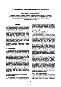
The architecture proposed here allows the development of complex multirobot behavior via hierarchical and sequential composition of control and estimation modes, and parallel composition of agents. This is schematically illustrated in Figure 1. All software components are called agents. For example, all robots are modeled as agents. Agents can communicate with each other and the human operator can interact with the agents. Agent definitions can have parameters that can be used to create different agents of the same type.
(a) Hierarchy in CHARON
(b) Robot software: Sensing and control Fig. 1 Architecture for multirobot coordination Variables, in addition to being typed, can be discrete or analog. Analog variables are updated continuously, while discrete variables are updated only upon initialization and mode switches. The variables of an agent are partitioned into input, output, and private to allow modular specifications. For example, the robot can receive estimates of the obstacles from other robots, and commands and specifications from the human operator on input channels, and it can send its own information to other robots or to the human operator on the output channels. While physical variables
such as the position and velocity of the robot are public, the sensory or control information that is internal to a robot is designated as private. The agent definition contains modes or behaviors that are available to the robot. Modes specify evolution of control. If the state of an agent is given by x ∈ ℜn, its evolution is determined by a set of differential equations:
x = f q (x, u ),
u = k q (x, z )
(1)
where u ∈ ℜm is the control vector, q ∈ Q ⊂ Z is the control mode for the agent, and z ∈ ℜp is the information about the external world available either through sensors or through communication channels. A mode definition includes transitions among its submodes. A transition specifies source and destination modes, the enabling condition, and the associated discrete update of variables. Each mode can have submodes, and there is a hierarchy of modes that is typical in most robot software. Our low-level implementation in C++ uses Live Objects. Live Objects have been developed as part of the software architecture for implementation on the hardware platforms. A live object encapsulates algorithms and data in the usual objectoriented manner together with control of a thread within which the algorithms will execute, and a number of events that allow communication with other live objects. At the top of the hierarchy, the algorithms associated with the objects are likely to be planners, whilst at bottom they will be interfaces to control and sensing hardware. The planner objects are able to control the execution of the lower level objects to service high-level goals. To offer platform independence, only the lowest level objects should be specific to any hardware, and these should have a consistent interface for communication with the more planning objects that control their execution. Visual servo control algorithms have been incorporated into the live object framework for such basic functionality as obstacle avoidance, wall-following, formation keeping, mapping and localization. Learning is also relevant to our work. Since this is not the main focus of this paper, we point the reader to a description of the Boundary Localized Reinforcement Learning (BLRL) to obtain locally optimal mode transition boundary locations [9].
4. Multirobot Coordination 4.1 Experimental platform The mobile robot we use for our experiments is shown in Figure 2. It has been constructed from a commercial radio-control truck kit. Some modifications have been made to improve shock absorption and to house an omnidirectional vision system, a 2.4 GHz wireless video transmitter, and a battery pack. The robot has a servo controller on board for steering and a digital proportional speed controller for forward/backward motion. A parallel port interface, also designed in our lab, allows driving up to 8 mobile robot platforms from a single Windows NT workstation. The receiver, located at the host computer, feeds the signal to a frame grabber that is able to capture video at full frame rate (30 Hz.) for
image processing. This yields a video signal in a format for viewing and recording, as well as image processing.
Fig. 2 The mobile robot platform with Omnicam(left), range mapping (right)
4.2 Sensors 4.2.1 Color feature extraction and target tracking Pixels corresponding to a target can be identified in the image using a YUV based color extractor which provides robustness to variations in illumination. Threedimensional color models are generated a priori from images of the target at numerous distances, orientations, and illumination levels. These data are stored in a pair of look-up-tables (LUTs) to speed image processing. During operation, the target detection algorithm – the blobExtractor sensor, is initially applied to the entire image and can run at frame rate (30 Hz). Once the target is acquired, the sensor switches to target tracking mode. The target tracking scheme is simple yet robust. To increase the speed of color feature extraction, a region of interest is dynamically constructed surrounding the target in the current image based on its location in the previous image. By constraining image processing operations to this region of interest, we are able to run multiple target trackers at frame rate. This allows us to assume little motion of the targets between consecutive image captures. Such small inter-frame movement thus permits the straightforward tracking process whereby the position of the region of interest (which is centered upon the target) is moved to coincide with the centroid of the target extracted from each frame. 4.2.2 Range mapping A Sobel gradient was applied to the original omnidirectional image. The resulting edges in the image were assumed to be features of interest, see Figure 2. By assuming a ground plane constraint, the distance to the nearest feature in the sector of interest was determined from the its relative elevation angle to the mirror. This provides a range map to all obstacles at frame rate. 4.2.3 Localizer We have implemented a localization algorithm for our mobile robots. The algorithm employs an extended Kalman filter (EKF) to match landmark observations to an a
priori map of landmark locations. The Localizer object uses the blobExtractor sensor to determine the range and the bearing of an observed landmark. If the observed landmark is successfully matched, it will be used to update the vehicle position and orientation. Figure 3 depicts a typical image used for localization. The kinematic model of the mobile robot is given by
x = u1 cos θ �
y = u1 sin θ �
u1 tan φ l φ = λ (u 2 − φ) θ= �
(2)
�
where l is the body length, u2 is the steering command, |φ| < 70° is the steering angle, and λ ≈ 4 s−1 is a parameter that depends on the steering servo time constant and wheel-ground friction. The control vector is given by u = [u1 u2]T .
Fig. 3 Image used for localization (left), experimental results (right)
4.2.4 Velocity estimator The leader-following control object described in the next section, requires reliable estimation of the linear velocity and angular velocity of a leader mobile robot. The velocity estimator algorithm is also based on an extended Kalman filter. It uses the blobExtractor sensor to determine the range ρ and the bearing β of the observed leader. In addition, the filter requires a sensor model, and the relative kinematic equations of the leader and follower robots. 4.2.5 Mapper We have implemented a cooperative mapping using three nonholonomic platforms. A simulated room 4m×4m was constructed. The positions of two robots are held fixed, while the third robot, called mapper, is driven around the test area. A global map updates is accomplished at 3-5 Hz. The experimental setup and results are displayed in Figure 4.
Fig. 4 Cooperative mapping 4.3 Controllers 4.3.1 Obstacle avoidance and wall following The wall follower works by using inputs from two live object sensors – a wall detector and an obstacle detector. Both take as input the image from an edge detector, and use range map data to find the relative position of the wall/obstacle. The wall detector has a 40° field-of-view from 160 to 200 degrees. A line is fit to these points using RANSAC (random sampled consensus), which gives us a line fit robust to outliers. From this we are able to extract the relative position and orientation of the robot to the wall. We use I/O feedback linearization techniques to design a PD controller to regulate the distance of the vehicle to the wall, Figure 5. Wall following can be considered as a particular case of path following. Thus, the kinematics in terms of the path variables become
π 2 θ p = θ − θt θt =
π 2 s = v1 cos θ p ,
θp = θ − �
θ p = v1 �
Fig. 5 The wall-follower
tan φ , l
(3)
d = v1 sin θ p �
φ = v2 �
Assuming the robot is to follow the wall with a piecewise constant velocity v1(t), the controller is given by
l (k p (d 0 − d ) − k v v1 sin θ p ) u = tan −1 2 v1 cos θ p
(4)
where u(t) is the steering command, v1(t) is the linear velocity, and kp, kv are positive design controller gains. Usually, we may want a critically damping behavior i.e.,
kv = 2 k p .
The obstacle detector picks up objects in its 80° forward-staring field-of-view. Since the position and orientation relative to the wall are known, the detector is able to discriminate which “obstacles” are actually the wall, and which are truly obstacles that must be avoided. Mode switching between wall following and obstacle avoidance is accomplished by giving priority to the latter. Experimental results are depicted in Figure 6 shows experimental results (axes units are inches).
Fig. 6 Sample wall-following configuration (left) and corresponding mode vs. position results (right) 4.3.2 Leader-Following Control We consider a team of n nonholonomic mobile robots that are required to follow a prescribed trajectory while maintaining a desired formation. The desired formation may change based on environmental conditions or higher-level commands. A robot designated as the lead robot follows a trajectory generated by a high-level planner g(t) ∈SE(2). The follower robots should maintain a prescribed separation and bearing from its adjacent neighbors. This controller (denoted Sepatation Bearing Controller SBC here) is implemented on each robot in the team. The desired separations lijd and bearings ψ ijd will define the shape of the formation, see Figure 7. The kinematics of the nonholonomic i-robot are given by
xi = vi cos θi �
yi = vi sin θi �
(5)
θi = ωi �
where xi ≡ (xi, yi, θi)∈SE(2).
Fig. 7 The Separation Bearing Control SBC
The control velocities for the follower are given by [10] v j = sij cos γ ij − lij sin γ ij (bij + ωi ) + vi cos(θi − θ j ) ωj =
1 [ sij sin γ ij + lij cos γ ij (bij + ωi ) + vi sin( θi − θ j )] dj
(6)
where
γ ij = θi + ψ ij − θ j sij = k1 (lijd − lij )
(7)
bij = k 2 (ψ ijd − ψ ij )
k1 , k 2 > 0
The closed-loop linearized system becomes
lij = k1 (lijd − lij ) �
ψ ij = k 2 (ψ ijd − ψ ij ) �
(8)
θj = ωj �
In the following theorem, we provide a stability result for the SBC [11]. Theorem 1. Assume that the reference trajectory g(t) is smooth enough, the reference linear velocity is large enough and bounded i.e., β max > vi > βmin > 0 , the reference angular velocity is small enough i.e., ωi < Wmax , and the initial relative orientation is bounded i.e., θi − θ j < ε θ < π . If the control velocities (6) are applied to Rj, then system (8) is stable and the output system error of the linearized system converges to zero exponentially. Remark. While the two output variables in (8) converge to the desired values arbitrarily fast (depending on k1 and k2), the behavior of the follower’s internal dynamics, θj , depends on the controlled angular velocity ωj. In our analysis we have considered the internal dynamics which is required for a complete study of the stability of the system. Let the orientation error be expressed as eθ = ωi − ω j (9) �
After some work, we have
eθ = − �
vi sin eθ + f θ (u, eθ ) dj
(10)
where u is a vector that depends on the output system error and reference angular velocity ωi. f θ (⋅) is a nonvanishing perturbation for the nominal system (10) which is (locally) exponentially stable. By using stability of perturbed systems [12], it can be shown that system (10) is stable, thus the stability result in Theorems 1 follows. Figure 8 (right) shows a view of leader-following experiment. These are actual data points collected from an overhead camera installed in our lab for ground truth purposes.
Fig. 8 Formation control experimental setup Figure 9 depicts the estimated linear and angular velocity of the leader robot, and the measured separation and bearing. We choose ld = 0.6 m and ψd = 180°. The robustness of the system is verified when we manually hold the follower for a few seconds at t ≈ 65 s. Estimated angular velocity (leader)
Estimated linear velocity (leader)
0.6
0.6
0.5 0.5
0.4
v 1 (m /s )
ω 1 (rad/s )
0.4
0.3
0.2
0.2
0.1
0.1
0
0.3
0
-0.1 0
20
40
60 80 Time (s)
100
120
140
0
20
40
Separation l
60 80 Time (s)
100
120
140
Bearing 200
0.8
195
0.7
190 185 180
ψ (deg)
A mplitude
(m)
0.6
0.5
175 170
0.4
165 160
0.3 155
0.2
150
0
20
40
60 80 Time (s)
100
120
140
0
20
40
60 80 Time (s)
Fig. 9 Leader following experimental results
100
120
140
5. Concluding Remarks We describe a formal architecture and high-level language for programming multiple cooperative robots. Our approach assumes that each robot has a finite set of behaviors or modes that it can execute, and the programming language is used to formally specify a set of conditions under which mode transitions take place. Thus the tasks performed by the multirobot system are uniquely specified as mode transition boundaries that are defined in the robots information space. Experiments have been carried out in complex scenarios where robots need to exhibit a variety of behaviors such as localization, target acquisition, collaborative mapping and formation keeping.
References [1]
Donald B, Gariepy L, Rus D (2000) Distributed manipulation of multiple objects using ropes, Proc. IEEE Int. Conf. on Robotics and Automation, 450-457. [2] Khatib O, Yokoi K, Chang K, et al. (1996) Vehicle/arm coordination and mobile manipulator decentralized cooperation, IEEE/RSJ Int. Conf. on Intelligent Robots and Systems, 546-553. [3] Parker L (2000) Current state of the art in distributed robot systems, Distributed Autonomous Robotic Systems 4, Parker L, Bekey G, Barhen J (eds.), Springer, 3-12. [4] Rus D, Donald B, Jennings J, (1995) Moving furniture with teams of autonomous robots, IEEE/RSJ Int. Conf. on Intelligent Robots and Systems, 235-242. [5] Brooks R (1986) A robust layered control system for a mobile robot, IEEE J. Robotics and Automation, 2(1):14-23. [6] Balch T, Arkin R (1998) Behavior-based formation control for multi-robotic teams, IEEE Transactions on Robotics and Automation, 14(6):926-934. [7] Alur R, Henzinger T, Lafferriere G, Pappas G (2000) Discrete abstractions of hybrid systems, Proceedings IEEE, 88(2):971-984. [8] Alur R, Grosu R, Hur Y, Kumar V, Lee I (2000) Modular specification of hybrid systems in CHARON, Proc. Int. Workshop on Hybrid Systems: Computation and Control. [9] Grudic G, Ungar L (2000) Localizing search in reinforcement learning, National Conference on Artificial Intelligence (AAAI 2000), 590-595. [10] Desai J, Ostrowski J, Kumar V (1998) Controlling formations of multiple mobile robots, Proc. IEEE Int. Conf. on Robotics and Automation, 2864-2869. [11] Fierro R, Das A, Kumar V (2000) Hybrid control of formation of robots, Submitted to IEEE Int. Conf. on Robotics and Automation, ICRA01. [12] Khalil H (1996) Nonlinear Systems, Prentice Hall.