Three-dimensional (3-D) chip stacking is touted as the silver bullet technology that can keep Moore's momentum and fuel the next wave of consumer electronics ...
A Framework for Architecture-Level Exploration of 3-D FPGA Platforms Harry Sidiropoulos, Kostas Siozios, and Dimitrios Soudris School of Electrical and Computer Engineering, National Technical University of Athens, Athens, Greece {harry,ksiop,dsoudris}@microlab.ntua.gr
Abstract. Interconnection structures in FPGAs increasingly contribute more to the delay and power consumption. Three-dimensional (3-D) chip stacking is touted as the silver bullet technology that can keep Moore’s momentum and fuel the next wave of consumer electronics products. However, the benefits of such a technology have not been sufficiently explored yet. This paper introduces a novel 3-D FPGA, where logic, memory and I/O resources are assigned to different layers. Experimental results prove the efficiency of our architecture for a wide range of application domains, since we achieve average performance improvement and power saving of 30% and 10%, respectively.
1
Introduction
Field-Programmable Gate Arrays (FPGAs) have become the implementation medium for the vast majority of modern digital circuits. This situation makes the FPGA paradigm to grow in importance, as there is a stronger demand for faster, smaller, cheaper, and lower-energy devices. For decades, semiconductor manufacturers have been shrinking transistor size to achieve the yearly increases in performance described by Moore’s Law, which exists only because the RC delay was negligible, as compared to the signal propagation delay. For sub-micron technology, however, the RC delay becomes a dominant factor. For instance, in the 130nm CMOS technology, approximately 51% of microprocessor power is consumed by interconnect, with a projection that without changes in design philosophy, in the next 5 years up to 80% of microprocessor power will be dissipated at interconnect [11]. This has generated many discussions concerning the end of device scaling as we know it, and has hastened the search for solutions beyond the perceived limits of current 2-D architectures. An emerging solution to this problem is the usage of 3-D integration, which replaces a large number of long interconnects (needed in 2-D structures) with shorter ones. More specifically, 3-D integration provides: (i) higher logic density in the same footprint area, (ii) shorter interconnections, (iii) reduced signal propagation delay, (iv) greater versatility and resource utilization, and (v) lower power consumption. The shift from horizontal to vertical stacking of circuits has the potential to rewrite the conventions of electronics design. J.L. Ayala et al. (Eds.): PATMOS 2011, LNCS 6951, pp. 298–307, 2011. c Springer-Verlag Berlin Heidelberg 2011 �
A Framework for Architecture-Level Exploration of 3-D FPGA Platforms
299
The benefits of using 3-D integration in logic chips are especially great for designing FPGAs since these devices already exhibit performance limitations that are tightly firmed to increased wire-length. However, in order such a technology to be widely accepted, several challenges need to be satisfied. Among others, new methodologies that support architecture-level exploration under different optimization goals are essential to design efficient 3-D architectures. Since this procedure is rather a complex task, there is also an increasing demand for developing CAD tools. Up to now, the majority of research related to 3-D integration can be summarized in three categories, namely: (i) the manufacturing and fabrication processes that is mainly guided by industrial research, (ii) the development of CAD algorithms and tools from the academia to support the design of emerging 3-D technologies, and (iii) the case studies about the design of general-purpose 3-D architectures. A number of 3-D FPGA architectures have been proposed until now both from academia and industry. For instance, previous efforts to model 3-D architectures affects both homogeneous (all the layers contain only logic blocks) [1][2][13], as well as heterogeneous approaches where each of the layers is specialized (i.e. memory, switches, logic, etc) [3]. Even though 3-D architectures with identical layers (first case) are suitable for designing 3-D FPGAs (due to their inherent regularity), the employment of a heterogeneous 3-D architecture potentially can provide additional performance improvement. In addition to that, there is a number of commercially available 3-D FPGAs. Typical instantiations are the 3-D FPGAs provided by Tezzaron Corp. [4], as well as the devices from Xilinx (e.g. Virtex-7 [5]). In this paper we propose a novel architecture template for designing heterogeneous 3-D FPGAs with layers that contain blocks of different type. More specifically, our case study affects a 3-D architecture consisted of three layers, where logic, memory and I/O blocks are assigned to different layers. Furthermore, we introduce also a novel framework that software supports the architecture-level exploration task, as well as the application mapping onto these 3-D FPGAs. To the best of authors knowledge, this is the first time in literature where such a software-supported architecture level exploration of heterogeneous 3-D FPGAs is presented. Even though in this paper we study 3-D FPGAs consisted of three layers, the proposed methodology and CAD tools are also applicable to any other 3-D device (e.g. with more layers and/or that contain different type of blocks). The rest of the paper is organized, as follows: Section 2 describes the motivation behind this work, whereas section 3 introduces the architectural template of proposed 3-D FPGA, as well as the supporting tool framework. Experimental results that prove the efficiency of proposed solution are shown in section 4. Finally, conclusions are summarized in section 5.
2
Motivation
The application’s complexity usually introduce constraints to the architecture of target FPGA. More specifically, the performance of many application domains
300
H. Sidiropoulos, K. Siozios, and D. Soudris
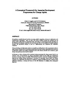
(e.g. telecommunication, encryption and image-video processing) usually depends on the availability of sufficient communication bandwidth. Previous studies [13] have already highlighted that communication between logic and memory blocks is significantly improved by the usage of 3-D integration. Hence, it is almost obvious that memory blocks have to be assigned into a different layer, as compared to logic infrastructure (e.g. slices). However, none of these works study up to now the impact of communication bottleneck between I/O blocks and the rest architecture. Existing FPGAs incorporate a limited number of I/O blocks, which are usually spatially assigned to the periphery of the device [7]. However, such a topological arrangement imposes that application’s networks that provide signal transmission among logic and I/Os exhibit increased wire-lengths, resistance and capacitance values. This problem becomes even more important for communication intensive applications, where the majority of utilized interconnection resources affect routing paths between logic (CLB) and I/O blocks. In order to depict this limitation, Fig. 1(a) shows the successful placement for a cryptographic application (named bigkey) [6]. The target architecture is a Virtex-based 2-D FPGA and the P&R was performed with timing-driven VPR tool [7]. The utilized logic blocks in this figure are depicted with grey color squares, whereas the lines correspond to routing paths between them (as they retrieved after global routing). Based on Fig. 1(a) we can conclude that the majority of connections affect routing paths between logic resources (distributed over the entire architecture) and a few I/O blocks (placed mostly for this application at the bottom-right corner of the device). These routing paths exhibit increased wire-length, and hence they result among others to considerable delay and power overheads.
(a)
(b)
Fig. 1. Benchmark bigkey (a) after placement and global routing with VPR and (b) a random network with at least one I/O block after detailed routing
A Framework for Architecture-Level Exploration of 3-D FPGA Platforms
301
Furthermore, networks that contain at least one I/O block are more likely to be scattered across the FPGA, as compared to the rest networks. This is also depicted in Fig. 1(b), where we highlighted with blue color lines the distribution of a randomly selected routing path that contain at least one I/O block. This info was retrieved after successful detailed routing of bigkey benchmark with VPR tool [7]. Based on previous conclusions, we can claim that existing way for assigning I/O blocks at the periphery of FPGA device introduce considerable performance limitations, especially for communication intensive applications. Hence, alternative architecture can be inspired. For this purpose, our introduced heterogeneous 3-D FPGA assumes that I/O blocks are assigned to a dedicated layer. Note that such an enhancement is complementary to the previous one (affecting logic and memory blocks to separate layers).
3
Proposed 3-D FPGA Architecture and Tool Flow
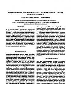
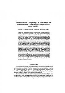
This section introduces the proposed architectural template for 3-D FPGAs, as well as the software framework for enabling architecture-level exploration and application mapping onto these devices. More specifically, logic, memory and I/O resources at this architecture are assigned to different layers, as it is depicted in Fig. 2. Note that the number of total layers is tunable in order to better match application’s requirements. The communication between resources assigned to different layers is provided through TSVs, which are actually implemented either inside vertically aligned switch boxes (SBs), or connection boxes (CBs). For this purpose we assume that these blocks are assigned to the same (x, y) co-ordinates, whereas the interlayer connections are depicted in Fig. 2 with dotted lines. Regarding the modeling of these TSVs, we used the electrical equivalent characteristics found in a recent technical published report for Tezzaron 3-D FPGA [12]. In order these routing resources to be aware about the third dimension, they appropriately extended similar to the way discussed in [8]. More specifically, connectivity between I/O and logic layers (Layers 1 and 2 at Fig. 2) is implemented inside 3-D CBs, whereas the 3-D SBs are employed for implementing connectivity between layers with CLBs and memories (Layers 2 and 3 at Fig. 2) [8]. Next, we introduce the design framework for supporting architecture-level exploration, as well as application mapping onto the proposed 3-D FPGAs with heterogeneous layers. The new tool framework, named 3-D NAROUTO, is public available through [10] for download and/or additional improvements. We have to mention that our solution differs compared to similar approaches (e.g. [1][2][13]), since it supports heterogeneous resources (e.g. logic, memories, DSPs, etc) which can be assigned to different layers. More details about the features of NAROUTO framework can be found in [10]. Fig. 3 gives an abstract view of the 2-D and 3-D NAROUTO frameworks. Note that during the development of 3-D NAROUTO, only the tools that are aware about the third dimension were appropriately extended, whereas the rest tools (e.g. synthesis and technology mapping) are identical between flows.
302
H. Sidiropoulos, K. Siozios, and D. Soudris
I/O (1,3)
I/O (2,3)
I/O (3,3)
SB
CB
SB
CB
CLB (1,3) I/O (1,2)
I/O (2,2)
I/O (3,2)
SB
CB
I/O (2,1)
I/O (3,1)
SB
CB
SB
CB
SB
CB
I/O (2,0)
I/O (3,0)
SB
CB
Layer 1 (I/O)
SB
CB
CB
SB
CB
SB
SB
CB
SB
SB
SB
SB
SB
SB
Layer 2 (logic)
SB Memory (3,3)
Memory (2,2)
SB Memory (3,2)
SB Memory (2,1)
Memory (1,1)
SB
SB Memory (2,3)
Memory (1,2)
CLB (3,1)
SB
SB Memory (1,3)
CLB (3,2)
CLB (2,1)
SB
SB
SB
CLB (3,3)
CLB (2,2)
CLB (1,1) I/O (1,0)
CB
CLB (2,3)
CLB (1,2) I/O (1,1)
SB
SB
SB Memory (3,1)
SB
SB
Layer 3 (memory)
Fig. 2. Architectural template of our proposed 3-D FPGA
APPLICATION DESCRIPTION IN HDL
SYNTHESIS
EXISTING 2D NAROUTO
PROPOSED 3D NAROUTO
TECHNOLOGY MAPPING
2D
3D
2D or 3D ?
HETEROGENEOUS BLOCKS
HETEROGENEOUS LAYERS
HETEROGENEOUS-BLOCKS AWARE MAPPING
MAPPING IN HETEROGENEOUS LAYERS
PLACEMENT & ROUTING
PLACEMENT & ROUTING
POWER CONSUMPTION ESTIMATION
POWER CONSUMPTION ESTIMATION
APPLICATION EVALUATION
Fig. 3. 2-D and 3-D NAROUTO design framework
After synthesis and technology mapping we deal with application P&R. Initially, this involves to generate an instance for the target 3-D FPGA based on the architectural template discussed in Fig. 2. For simplicity reasons, we assume (without affecting the generality of introduced solution) that all the layers occupy the same area (3-D cube architecture).
A Framework for Architecture-Level Exploration of 3-D FPGA Platforms
303
The employed P&R algorithms at 3-D NAROUTO are based on VPR tool [7], but they have extensively modified in order to be aware about: (i) the additional flexibility imposed by the 3-D integration, and (ii) the heterogeneous blocks (e.g. memories) found in target architecture. Similarly, the application’s routing is based upon an extended version of Pathfinder algorithm [7], which repeatedly rips-up and re-routes each net of the design, until all the congestions to be resolved. Since interlayer connections exhibit shorter wire-lengths compared to the routing tracks found in the same layer but their number is significantly limited, our routing algorithm penalties their non-efficient utilization. For this purpose we encode TSV connections as high cost edges at the platform graph. Hence, their usage is prohibited whenever they do not used at timing critical networks.
4
Experimental Results
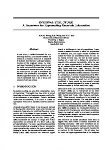
This section provides a number of comparison results that prove the efficiency of our solution with the usage of MCNC [6] and Altera QUIP [14] benchmark suites. In order to software support the application implementation onto 2-D and 3-D FPGAs, we employ the VPR [7] and our proposed 3-D NAROUTO framework, respectively. Finally, for shake of completeness we have to mention that both 2D and 3-D architectures incorporate the same number of logic (CLBs), memory and I/O blocks. In order to study all the potential architectural solutions, in this section we provide results about three alternative scenarios which are summarized, as follows: – Study the impact of I/O bottleneck: We evaluate the efficiency of a 3-D FPGA, where logic and I/O blocks are assigned to different layers. – Study the impact of stacking memory onto logic: Our 3-D FPGA consists of two layers, where the first layer contains logic and I/O blocks, whereas memories are assigned to second layer. – Study a combination of the previously mentioned architectures: This scenario involves a 3-D FPGA, where logic, memory and I/O blocks are assigned to different layers. The first set of experimental results quantifies the efficiency of assigning I/O blocks to a different layer, as compared to logic resources. For this purpose, our 3-D architecture is composes by two layers, while the evaluation is performed by employing a well established benchmark suite [6]. Note that during this study we need benchmarks without memory blocks, since they introduce additional (artificial) overhead at routing networks. In order to depict that our 3-D architectures is superior as compared to conventional 2-D FPGAs, Fig. 4 gives the average wire-length for networks that contain at least an I/O block (blue color bars), or not (red color bars). Based on this figure, we can conclude that the average wire-length for networks with at least one I/O is about 92% higher, as compared to the rest
304
H. Sidiropoulos, K. Siozios, and D. Soudris
100%
90%
80%
70%
60%
50%
40%
30%
20%
10%
0%
Average wire-length for CLB net
Average wire-length for I/O net
Fig. 4. Average wire-length for routing paths that contain (or not) I/O blocks
networks (those that include only logic resources). Furthermore, this trend is common for all the benchmarks. This proves our inspiration discussed in section 2, that networks with I/Os are significantly longer. Hence, by assigning these I/O blocks to a different layer, as our 3-D architecture proposes, we expect reasonable wire-length, delay and power improvements. In conjunction to this conclusion, Table 1 gives the maximum operation frequency and power consumption for such a 3-D architecture, as compared to the corresponding 2-D FPGA. Note that both 2-D and 3-D architectures contain the same number of logic, I/O blocks and routing tracks per channel. From this table it is evident that the average performance improvement achieved by the usage of proposed 3-D architecture is 22%, without any power consumption overheads. Furthermore, in conjunction to Fig. 4, there are some applications that achieve considerable delay reduction due to better manipulation of networks that contain at least one I/O block and span the entire architecture. Typical examples for this conclusion are the bigkey, des, dsip and ex1010 benchmarks, which increase maximum operation frequency by 88%, 46%, 42% and 58%, respectively. Note that additional performance improvement is feasible in case we alleviate the constraint regarding the same power budget. After quantifying the efficiency of improving I/O bandwidth, we study the impact of assigning memory blocks to a different layer, as compared to logic resources. For this purpose, we employ a number of benchmarks from QUIP suite [14]. Table 2 evaluates the maximum operation frequency and the power
A Framework for Architecture-Level Exploration of 3-D FPGA Platforms
305
Table 1. Evaluation of I/O improvement between 2-D and the proposed 3-D FPGA Benchmark alu4 apex2 apex4 bigkey des diffeq dsip elliptic ex1010 ex5p frisc misex3 pdc s298 s38417 s38584 seq spla tseng Average:
Max. Operation Frequency (MHz) Power Consumption (mW) 2-D FPGA 3-D FPGA Gain (%) 2-D FPGA 3-D FPGA Gain (%) 126.58 128.21 1.28% 47.29 46.12 -2.47% 101.01 111.11 10.02% 63.4 62.35 -1.66% 120.48 129.87 7.79% 37.78 36.65 -2.99% 104.17 196.08 88.24% 22.79 22.89 0.44% 105.26 153.85 46.15% 62.71 62.59 -0.19% 116.28 140.85 21.13% 35.89 35.89 0.00% 156.25 222.22 42.22% 80.96 80.75 -0.26% 65.36 84.75 29.66% 46.02 45.18 -1.83% 43.10 68.49 58.90% 121.01 120.86 -0.12% 121.95 131.58 7.89% 44.38 43.89 -1.10% 55.25 57.80 4.63% 130.61 129.74 -0.67% 131.58 149.25 13.43% 55.84 51.67 -7.47% 59.52 80.00 34.40% 84.18 83.46 -0.86% 75.19 76.92 2.308% 48.6 51.05 5.04% 81.30 83.33 2.50% 76.06 80.19 5.43% 96.15 104.17 8.33% 63.8 71.19 11.59% 113.64 129.87 14.29% 58.81 58.54 -0.45% 84.03 94.34 12.264% 235.58 232.47 -1.32% 161.29 178.57 10.71% 25.75 25.93 0.71% 100.97 122.17 21.90% 70.61 70.60 0.10%
Table 2. Evaluation of memory bandwidth optimization between 2-D and the proposed 3-D FPGA Max. Operation Frequency (MHz) Power Consumption (mW) 2-D FPGA 3-D FPGA Gain (%) 2-D FPGA 3-D FPGA Gain (%) oc aes core inv 101.58 131.96 29.91% 0.723 0.821 -13.48% ata ocidec 141.67 248.27 75.25 0.148 0.107 27.76% os blowfish 93.55 94.17 0.67% 0.250 0.221 11.75% oc hdlc 176.40 207.26 17.50% 0.182 0.167 8.22% oc minirisc 131.55 156.25 18.78% 0.066 0.057 13.63% Average: 128.95 167.58 28.42% 0.31 0.27 9.58% Benchmark
dissipation, when these benchmarks are mapped onto 3-D FPGAs with two layers (logic and memory). Experimental results from this study shown that our proposed 3-D stacking improves the performance of target architectures, since it results to higher bandwidth between memory and logic resources. More specifically, there is an average delay and power reduction by 29% and 10%, respectively, as compared to the corresponding 2-D FPGAs. These improvements occur mainly due to shorter wires that provide signal communication between logic (CLBs) and memory blocks. Note that usually, these connections are formed from wider routing channels in order to achieve the desired data-path implementations, and hence their impact is much more important than existing implementations of 3-D FPGAs (e.g. [1][2][13]) which assume that different layers are formed solely from CLBs.
306
H. Sidiropoulos, K. Siozios, and D. Soudris Table 3. Evaluation of the proposed 3-D FPGA architecture
Max. Operation Frequency (MHz) Power Consumption (mW) 2-D FPGA 3-D FPGA Gain (%) 2-D FPGA 3-D FPGA Gain (%) oc aes core inv 101.58 129.40 27.41% 0.723 0.783 -8.30% ata ocidec 141.67 243.49 71.87% 0.148 0.137 6.74% os blowfish 93.55 115.08 23.017% 0.250 0.274 -9.74% oc hdlc 176.40 198.53 12.55% 0.182 0.172 5.65% oc minirisc 131.55 152.58 16.01% 0.066 0.071 -7.37% Average: 128.95 167.82 30.16% 0.27 0.29 -2.61% Benchmark
Finally, we evaluate application mapping onto 3-D FPGAs, where both I/Os and memories are assigned to different layers, as compared to logic resources. For this purpose, Table 3 summarizes the impact of implementing these benchmarks onto an architecture with three layers. From the results summarized in Table 3 we can conclude that our architecture achieves performance improvement by 30% with a negligible penalty in power dissipation (increase by 2.6%).
5
Conclusion
This paper introduces a novel 3-D FPGA architecture, where I/O and memory blocks are assigned to different layers as compared to logic resources. The new architecture is software supported by a public available software framework, named 3-D NAROUTO. The evaluation procedure proves the efficiency of proposed hardware/software solution, as it achieves application implementation with significant shorter wire-lengths, which in turn leads to mentionable delay and power improvements. More specifically, average delay and power reduction by 30% and 10%, respectively, is feasible as compared to conventional 2-D FPGAs.
References 1. Das, S., Chandrakasan, A., Reif, R.: Design tools for 3-D integrated circuits. In: Proc. of ASP-DAC, pp. 53–56 (2003) 2. Ababei, C., Mogal, H., Bazargan, K.: Three-dimensional Place and Route for FPGAs. IEEE Trans. on CAD 25(6), 1132–1140 (2006) 3. Lin, M., El-Gamal, A., Lu, Y., Wong, S.: Performance benefits of monolithically stacked 3-d fpga. IEEE Trans. on CAD 26(2), 216–229 (2007) 4. 3-D FPGA from Tezzaron, http://www.tezzaron.com/about/PhotoAlbum/Products/3D_FPGA.html 5. Xilinx Stacked Silicon Interconnect Technology Delivers Breakthrough FPGA Capacity, Bandwidth, and Power Efficiency. White paper: Virtex-7 FPGAs, Xilinx Inc. (October 2010) 6. Standard Cell Benchmark Circuits from the Micro-electronics Center of North Carolina (MCNC), http://vlsicad.cs.binghamton.edu/gz/PDWorkshop91.tgz 7. Betz, V., Rose, J., Marquardt, A.: Architecture and CAD for Deep-Submicron FPGAs. Kluwer Academic Publishers, Dordrecht (1999)
A Framework for Architecture-Level Exploration of 3-D FPGA Platforms
307
8. Hsu, C., et al.: Interlaced switch boxes placement for three-dimensional FPGA architecture design. Int. Journal of Circuit Theory and Applications, doi: 10.1002/cta.739 9. Jang, D., et al.: Development and evaluation of 3-D SiP with vertically interconnected Through Silicon Vias (TSV). In: Proc. of ECTC, pp. 847–852 (2007) 10. Electronic document, http://proteas.microlab.ntua.gr/ksiop/software.html 11. Magen, N., et al.: Interconnect-Power Dissipation in a Microprocessor. In: ACM System-Level Interconnect Prediction Workshop (February 2004) 12. Gupta, S., et al.: Techniques for Producing 3-D ICs with High-Density Interconnnect. In: Int. Conf. VLSI Multi-Level Interconnection Conference (2004) 13. Siozios, K., Pavlidis, V., Soudris, D.: A Software-Supported Methodology for Exploring Interconnection Architectures Targeting 3-D FPGAs. In: Proceedings in Design, Automation and Testing in Europe (DATE), Nice, France, pp. 172–177 (April 2009) 14. Altera QUIP Benchmark suite, http://www.altera.com 15. Sidiropoulos, H., Siozios, K., Soudris, D.: A Methodology and Tool Framework for Supporting Rapid Exploration of Memory Hierarchies in FPGAS. In: International Conference on Field Programmable Logic and Applications (FPL), September 5-7 (2011)