84
IEEE TRANSACTIONS ON INDUSTRIAL INFORMATICS, VOL. 3, NO. 1, FEBRUARY 2007
A Framework for CAD- and Sensor-Based Robotic Coating Automation Z. M. Bi and Sherman Y. T. Lang
Abstract—Coating automation of a complex product family with changes and uncertainties is investigated. A CAD- and scannerbased robotic coating system is proposed. Its software system consists of a data-processing system and automatic programming and simulation system. The data processing system is capable of generating accurate surface model from points-cloud and/or as-designed CAD model. The automatic programming and simulation system is capable of creating robot programs based on the surface models. In this paper, the system framework and the methodology for generating robot programs are focused. Index Terms—CAD-based system, coating, robotics and automation, sensor-based systems, surface treatment.
I. INTRODUCTION
N
UMEROUS products need to be coated to improve the visual appearance and/or provide protection from corrosion or damage. Coating is usually regarded as an essential finishing process for many products. Due to the complexity, coating processes have been less automated and many of the coating activities are undertaken manually. For example, 23% of the workers are involved in painting in the shipbuilding industry [1]. Manual coating operations cause many problems such as environment pollution, coating material waste, inconsistent quality, and low productivity. Therefore, coating automation has drawn a great attention for its potential value in solving those problems. Coating automation is expected to: 1) reduce costs by minimizing overspray, and decreasing the reject rate; 2) improve quality from optimizing process parameters; 3) increase productivity via efficient automated devices; and 4) reduce health and safety risks with the operators removed from a coating environment. II. OVERVIEW OF COATING AUTOMATION
Robotic systems have been applied in coating sanitary ware [2], [3], bumpers [4], shipbuilding [5], vessels [6], and automotive parts [7]–[10]. Some good reviews have been made on the state of the art of coating automation [11]–[16]. Based on the degree of automation, the automations have been classified into three levels. At a lower level, there is no robot program. A robot is manually controlled by means of a Manuscript received September 17, 2005; revised February 13, 2006 and September 5, 2006; acceptedDecember 15, 2006. Paper no. TII-06-09-0107. The authors are with the Integrated Manufacturing Technologies Institute, National Research Council of Canada, London, ON N6G 4X8 Canada (e-mail:
[email protected]). Color versions of one or more of the figures in this paper are available online at http://ieeexplore.ieee.org. Digital Object Identifier 10.1109/TII.2007.891309
joystick outside the coating booth. In some cases, control commends for a robot can be recorded and then repeated for the same operation. At an intermediate level, a robot program is generated by manually teaching. The system is developed for one product, and it is inflexible to adapt any changes. At a high level, a system is developed for product variants. Robot programs have to be generated automatically during system operating [17]. Most of the developed systems are at a low or intermediate level. The main challenge of developing a high-level system is to generate robot programs automatically. Robot programming techniques will be overviewed in the following sections, and they will be classified in terms of the products they can be used for, since the complexity of programming depends on the characteristics of product surfaces. A. Approaches for a Parametric Surface For a product with a parametric surface, two basic approaches can be applied [18], [19]. The first one is called the section approach. Robot paths are generated by intersecting the target surface with a series of parallel equidistant section planes. The second is called the offset curve approach that generates a start curve on the target surface, and then constructs the subsequent paths by offsetting the start curve along a family of curves orthogonal to the start curve. For both approaches, two subtasks are: 1) to choose a start curve or sweep direction and 2) to determine the optimum spacing between adjacent strokes [18]. B. Approaches for a Product With a CAD Model For a product with product variants, it is ideal that CAD models are accessible, and robot programs can be generated directly based on the CAD models. The approaches developed for a product family with CAD models include the folding approach and CAD-based approach. The folding approach was introduced by Hertling et al. [10]. To apply it, a 3-D product model is unfolded into a 2-D model. Paths will be generated in 2-D and then translated into 3-D. No details of this approach have been disclosed. However, the developers have found that the approach works only for product with smooth low-curvature surfaces. The CAD-based approach is presented by Sheng et al. [9]–[11]. In this approach, a surface model is approximated by a set of flat patches. Each patch is treated individually to generate a robot path. To determine a flat patch, the product model is firstly represented by a set of small triangles. The triangles with close directions and locations are then combined into a flat patch. This approach is generalized in the sense that the approach allows the changes of the product CAD model; however, for a complex surface with many small details shown
1551-3203/$25.00 © 2007 IEEE
BI AND LANG: A FRAMEWORK FOR CAD- AND SENSOR-BASEDROBOTIC COATING AUTOMATION
85
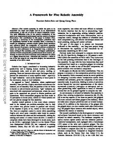
Fig. 1. Example of an irregular surface with small details.
in Fig. 1, large flat patches might not be found. The result can be a large number of small flat patches with a short path. Moreover, the connections of these short paths will become a new challenge. C. Approaches for a Product Without a CAD Model It is very common that a product has no CAD model or a product is changed after its CAD model is finalized. In this situation, a vision sensor system has to be used to capture a product surface or the changes different from as-designed CAD model. A sensor-based approach is proposed for the products with unknown features by Vincze et al. [20]–[22]. The features of a product are detected, and they are approximated by some simple elements such as flat, spherical, cylindrical, and conical surfaces. The paths are generated for these features individually. The sensor-based approach provides a solution to deal with changes and uncertainties of a product. It is ideal in terms of its flexibility. However, no methodology is available to deal with the robot programming for complex features. D. Summary Most of the application systems are designed for one product whose features are not changed, and robot programs are generated through trivial and time-consuming manually teaching. A few of the CAD-based or sensor-based coating systems have been proposed to deal with the changes and uncertainties of products. However, the capabilities of these systems are limited by the fact that available path-generation approaches work only for the flat or low-curvature parametric surfaces. Those systems meet the challenges in the following situations. 1) A product family has many product variations. Products are mixed in a coating process, and all of the products have to be coated in the same system. 2) A product has a complex surface. It includes many small features, such as the fasteners in Fig. 1. The sizes of these features are relatively small in comparison to the coverage area of a coating tool, but they are not so small as to be ignored. These features have to be dealt with together to generate a meaningful robot path. 3) A product is large in comparison to the working volume of a robot. Multiple robots are demanded to perform coating for it. Although the paths can be generated individually for
Fig. 2. System framework.
the surfaces of the product, the paths have to be decomposed so that the path segments can be assigned to individual robots. 4) Path generations take into consideration the collision and robotic reachability. A path on an individual surface may be adjusted due to the environmental constraints. Thus, the generated path from an individual surface might not be reliable, and needs to be changed with the consideration of other surfaces, robots, or the coating environment. In this paper, a new approach will be proposed to meet the challenges in above situations. The new approach is similar to the CAD-based approach, in the sense that the triangulated CAD model is used to generate robotic paths [7]–[9]. However, two significant differences are: 1) a robot path is viewed as a set of tag points on an arbitrary surface, rather than some parallel motion strokes on a simple and parametric surface and 2) the triangles in the model are used to calculate the tag points of a robotic path, rather than to approximate the surface as some simple features. As a result, the new approach has a great flexibility to adapt complex surfaces and changes of products. III. SYSTEM FRAMEWORK As shown in Fig. 2, the system framework includes a software system and a hardware system. The software system consists of a data processing system and an automatic programming and simulation system. A data processing system is responsible for acquiring and processing geometric data related to the products, robots, coating tools, and the coating environment. In particular, it is responsible for processing raw points cloud data from the detection workstation when the product is loaded into the
86
IEEE TRANSACTIONS ON INDUSTRIAL INFORMATICS, VOL. 3, NO. 1, FEBRUARY 2007
system. An automatic programming and simulation system is responsible for calculating tag points, generating robot paths and trajectories, and performing an integrated simulation. The hardware system is responsible for actual detecting and coating operations for the product family. A. The Hardware System The hardware system includes a detecting system where the product features or changes are detected and a coating system where the robots perform the coating operations. The detection system is used to acquire: 1) a product surface or the derivation of the surface from original product model and 2) the actual position where the product is located. Laser scanners and a motion tracker will fulfill these two functions, respectively. Laser scanners are used to acquire raw points cloud data from the product surface. Multiple views are required to get the data from the entire surface. Data from all of the views, as well as the CAD model, will be integrated to generate the accurate surface model, and the tag points of coating will be calculated based on this model. A motion tracker detects the actual position of a product along with the conveyer or railway system. Both of the orientation and position changes need to be calculated in generating a robot trajectory. Robots in the coating booth perform actual coating processes. Robot programs are customerized for each product, and they are downloaded from the automatic programming and simulation system. The robots execute the programs to get the product coated. B. The Software System The software system includes a data processing system for generating product surface models and an automated programming and simulation system for robot programming. 1) Data Processing System: The inputs of the data processing system are: 1) a points-cloud of the as-built product from the detection system and/or 2) the original CAD model of the as-designed product. The output of the system is an accurate surface model of the product. It is a very complex process to generate a surface model from points-cloud and/or a CAD model. Generally, the following tasks are required. Firstly, the acquired data is filtered to eliminate invalid data. Secondly, the data from different views acquired under different coordinate systems is registrated and merged under the same coordinate system. Thirdly, surface reconstruction is performed to generate an accurate surface from points-cloud and/or replace new surface patches on the original CAD model. Methodologies to accomplish these tasks have been well studied, and many software tools, such as the PolyWorks of the InnovMETRIC Software, are commercially available. However, the development of a cost-effective system customized to a specific application is still very challenging. In our studies, the open-source objected-oriented tools Visualization Toolkit (VTK) [23] and Insight Toolkit (ITK) [24] are utilized to develop a data processing system. ITK/VTK are among the most powerful toolkits for data and image processing. Although they are originated from medical applications, most of efficient and popular data processing algorithms have been embodied. Our data processing system is developed
Fig. 3. Example of triangulated surface models.
under a Java-based platform, and the ITK/VTK algorithms have been wrapped and integrated. However, a reader should note the data processing system is not the focus of this paper and the system itself is still under development. Not all types of surface models can be used directly to generate robot programs. In the programming methodology we will introduce, the product surface needs to be triangulated, and the size of a triangle on the surface must be “regular” and “small” enough to fit in a coating cone. It can be achieved by controlling the longest edge of a triangle in generating a triangulated surface model. Some CAD tools, such as Envision [25], include the tool to triangulate a surface model for a coating process. As shown in Fig. 3, the original surface model is in a stereolithography (STL) format, in which the triangles cannot fit in a coating cone appropriately. However, half of the model has been processed in order that the longest edge of a triangle becomes smaller than the size of a coating cone. 2) Automatic Programming and Simulation System: The input of the automatic programming and simulation system is a surface model from the data processing system, and the outputs are executable robot programs to the automatic robotic coating system. The system also includes a simulation module, which is used to evaluate and validate robot programs and coating quality. The system needs kinematic models of the motion devices such as coating robots, a railway and a fixturing system. Since the path generation must take into considerations of the reachability of these motion devices and collision detections. IV. METHODOLOGY FOR AUTOMATIC PROGRAMMING Other methodologies treat a robot path as a set of motion strokes. Since a motion stroke can run only on a smooth and relatively large surface patch, those methodologies lack the flexibility to deal with nonparametric or irregular complex surfaces. In our approach, a robot path is dealt with a set of points, so that the maximum flexibility can be achieved in automatic robot programming. Robotic path generation involves two tasks: 1) to determine a set of tag points so that a robot could learn where it goes to cover the product surface with coating materials and 2) to determine a sequence of the tag points so that a robot could
BI AND LANG: A FRAMEWORK FOR CAD- AND SENSOR-BASEDROBOTIC COATING AUTOMATION
(a)
(b)
(c)
87
Fig. 5. Triangulated compound surface.
Fig. 4. Tag points, path, and trajectory on a surface. (a) Tag points. (b) Path. (c) Trajectory.
learn how to pass through all these tag points to get the surface covered. As shown in Fig. 4(a), a tag point is a posture of a coating tool for a small surface area. By coating from this point, the small surface area can be covered by coating materials with the required thickness and quality. As shown in Fig. 4(b), a path is an optimal sequence of tag points that a robot passes through all tag points with a collision-free motion. When a robot moves from one tag point to another, its motion should be programmed. As shown in Fig. 4(c), a trajectory is a motion profile when a robot is controlled to follow a coating path. To present the new approach, the following assumptions are made. 1) A product family has many large and complex product variants. Each product has an external surface required to be coated. The surface includes many “small” features, such as fasteners on a chassis. A “small” feature implies that its area is smaller in comparison to that of a coating cone. 2) A product surface in the CAD model can be represented by a set of small triangles. Fig. 5 illustrates an example how a compound surface is represented by a set of the triangles. 3) A coating process can be approximated by a series of discrete operations. In each operation, a robot is moved to a tag point and it operates coating for a period of time until the corresponding coating area is covered with the required thickness. A coating cone refers to an area which can be covered by coating materials when the robot operates coating on its tag point. In Fig. 6, a coating cone is represented by two vectors and a scalar, the vectors represent a tag point and the direction, respectively, and a scaler is the radius of circle within which the coating materials can be accumulated to the required thickness. 4) In a coating cone, the triangles within the specified ranges and directions can be covered by the required thickness of the coating materials. A triangle is represented by a scalar and two vectors, the scalar represents its area, the first vector represents its geometric centre, and the second vector represents the direction of the triangle. A triangle located in a coating cone means that the centre of the triangle lies in the cone in a specified height range, and the orientation of the triangle is within the specified range in comparison with the orientation of the coating cone. 5) A robot has a limited motion capability in terms of the sizes of a product. Multiple robots are needed for the coating of the entire product.
Fig. 6. Triangles covered by a coating cone.
In the following, some key tasks in the new methodology will be discussed. A. Calculation of Tag Points A tag point represents a coating cone. The triangles in a coating cone will be covered by coating materials. The triangles are grouped to define the tag point. All of triangles on the product surfaces have to be examined so that each of them is covered by a certain coating cone. As shown in Fig. 7, the following procedure is applied to calculate tag points of a product surface. 1) Select a triangle at one extreme corner of the external surface; define a coating cone whose centre of the coating area is located at the centre of the triangle. 2) Check the neighboring triangle, and add it to the group as long as it lies in the coating cone. The center and direction of the coating cone are updated by weighting the centers and directions of two triangles. Repeat this procedure until no neighboring triangle can be found in this coating cone. 3) Refine a coating cone, whose tag point is calculated by weighting the centers and directions of all of the triangles within the coating cone. 4) Search the neighboring triangles along a searching direction to find the closest new one which has not been covered by another tag point, and repeat 2)–3) along other two searching directions until all triangles are covered. The above procedure is implemented and programmed. Using the program, the tag points of some example parts have been calculated. As shown in Fig. 8, the left side is the surface models of these parts. The right side is the corresponding models with tag points. Each tag point corresponds to a coating cone, which is represented by a red cone.
88
IEEE TRANSACTIONS ON INDUSTRIAL INFORMATICS, VOL. 3, NO. 1, FEBRUARY 2007
Fig. 7. Determination of tag points.
Fig. 10. Module for classifying tag points.
Fig. 11. Path generation.
Fig. 8. Examples of parts with coating cones. (a) Cylinder. (b) Sphere. (c) Chassis.
system when the tag points are assigned to individual robots. The position of a robot workspace, as well as the location where a product accepts a coating process, is determined. Therefore, a tag point can be assigned to a robot based on its position and orientation relative to the local coordinate system of the product. As shown in Fig. 10, a program is developed to classify tag points on the surface of a chassis model into eight groups: left side, right side, left-up side, right-up side, left-middle side, right-middle side, left-down side, and right-down side. A tag point is classified in term of its position and orientation. The highlighting area is the surface corresponding to the tag points on the right side. The tag points on each group will be put into an individual robot path. C. Path Generation
Fig. 9. Task assignments of robots.
B. Assignment of Tag Points Robots must move to the tag points for a coating process. The tag points must be assigned to individual robots before robot paths are generated. As shown in Fig. 9, if a tag point lies in the workspace of a robot, this point can be assigned to this robot. The layout of a coating cell determines whether or not a robot is capable of reaching a working point on a surface. The layout of the coating workcell is known to the automatic programming
A robot path is a sequence of the tag points. After the tag points have been assigned to robots, one needs to specify a sequence for a robot to pass through all of them. As shown in Fig. 11, each robot has to generate its paths individually. Path generation can be formulated as a traveling salesman problem (TSP), which is described as: “given a number of locations and the costs of traveling from one location to any other location, what is the cheapest round-trip route that visits each location once and then returns to the starting position”. TSP is a classic problem in combinatorial optimization. Many algorithms have been developed to solve a TSP [26], [27]. One challenge is that computing time increases exponentially with
BI AND LANG: A FRAMEWORK FOR CAD- AND SENSOR-BASEDROBOTIC COATING AUTOMATION
89
Fig. 13. Reduction of computation in collision detection.
Fig. 12. Examples of path generation. (a) Cylinder. (b) Sphere. (c) Chassis.
the number of tag points. To reduce the computing time, a simplified algorithm is proposed: the volume of the product is divided into small cells to control the number of tag points at each step. A tag point in an extreme unit of the surface is chosen as a staring point, the distances from this point to other tag points in the same or neighboring units are compared, and the point with the shortest distance is selected as the next point in a path. The calculation stops until all of tag points are included in the path. Fig. 12 illustrates some examples of the parts with the generated paths. In Fig. 12, a tag point is represented by a wire frame cone, and a path is specified in white color. The constraints of robotic capabilities and the collisions have not been taken into consideration. Note that the time is critical factor for the path generation of a complex product family. To fit automatic programming in the specified production cycle time, off-line path generations can be performed a priori based on as-designed CAD model of the product. When new features are detected, path generations for these features can be performed separately to define the required tag points. Then, robot paths are modified to insert all of the new tag points into the nearest path segments. D. Trajectory Planning From the viewpoint of the product, a path tells a robot where it should move around to coat the product surface. From the viewpoint of a robot, a trajectory tells a robot how it should move around in coating. At this stage, two primary considerations are: 1) free of collision and 2) the coating quality and evenness of the coating materials. A tag point of a robot has to be validated if it is free of the collision. A collision is defined that a small triangle on the surface of one object is intersected with a triangle on the surface of another object. The approaches to detect an intersection of a triangle pair have been well studied, and some open-source algorithms are available [28]. For a coating process, a collision can happen between a coating robot and the coated product. To
detect a collision, the models of the objects on the robot are also triangulated like the model of the product. The triangles from the objects and those from the product are paired and validated whether or not an intersection occurs. Collision detection involves intensive computation when the product is large in size and the number of the triangles on its surface is big. In Fig. 13, the product volume is divided into small cells, so that the triangles only in the interesting cells close to the tag point is located are needed to be detected. This can reduce the computation dramatically. For the tag points with a collision, they should be adjusted within the range of a robot workspace. If the adjustment does not succeed, the corresponding tag point has to be eliminated from the robot path, and the corresponding unreachable area must be indicated for a manually touch-up compensation. The generated paths ensure the coverage of product surface. However, the coating quality, such as the thickness and evenness of coating materials, depends on the process parameters in coating and robot trajectory planning. The process parameters should be selected to spray sufficient materials on the product surface at a right direction and constant distance. Besides, the robot velocity plays a significant role in coating quality. A robot usually has a continual motion and coating materials can be overlapping between two tag points. Accumulation of coating material on a certain surface depends on the time duration the coating tool moves over it. Cartesian velocity along the robot trajectory has to be planned as constant as possible to obtain the evenness of coating materials. The magnitude of the velocity will be determined via a trial and error method in simulation to ensure the required thickness of coating materials is accumulated on given product surface. E. Program Implementation The methodology for the aforementioned tasks has been implemented. To validate the methodology and visualize the results, an interface has been developed in the Java environment. As shown in Fig. 14, the embedded program generates a robot path in three steps: 1) to specify a text file where a product CAD model is stored; 2) to activate the “Generate Cones” module to calculate tag points for the surface needed to be coated; and 3) to run the “Generate Paths” module to generate robot paths for each group of tag points. The coating cones corresponding to tag points, as well as the generated paths, can be displayed, and the user is allowed to change the graphic view interactively. The efficiency of the program has been tested using different product models with the sizes ranging from one to hundreds of megabytes. One needs less than a minute to generate robot paths
90
IEEE TRANSACTIONS ON INDUSTRIAL INFORMATICS, VOL. 3, NO. 1, FEBRUARY 2007
Fig. 15. Chassis painting simulation in ENVISION. Fig. 14. CAD-based path-generation program.
for a surface model, and the time actually includes the duration the program loads the CAD model into the system. Note that the vision system needs much longer time to acquire pointscloud from a product; the time spending on path generation is not significant. V. INTEGRATED SIMULATION The aforementioned program ensures the generated robot paths to cover the surface completely. However, the coverage is not always the only requirement of a coating process. Other factors, such as the evenness and thickness of coating materials, have to be considered. These factors will depend largely on some parameters in a coating process, such as the speed of the tool center point (TCP) and the fluid flow rate of coating gun, and these parameters have to be finalized through a trial and error experiment or simulation. The coating model and the algorithm for the evaluation of coating performances will be required; various models and algorithms have been proposed to tackle this issue [29]–[32]. However, no comparison has been made in this paper, and the model and algorithm embodied in the ENVISION will be applied directly. Integrated simulation provides a highly detailed 3-D view of automatic coating workcell. The purposes of integrated simulation are: 1) to evaluate the performance of path generation and trajectory planning; 2) to validate system response to abnormal events; 3) to provide an efficient way to detect possible collisions in automatic coating process; 4) to predict the quality, productivity, and efficiency of coating under the given coating condition; 5) when 100% coverage can not be reached, the simulation can tell where the coating material is missing and manual compensation is required; and 6) to serve as a monitoring platform at the phase of the system operation. ENVISION [25] provides a specialized module for robotic painting process simulation. The system simulation is able to provide some valuable information such as paint distributions on product surfaces, productivity, cycle time, and the utilization of system facilities. However, the paths or trajectories of robots have to be determined manually by the users. In Fig. 15, a coating workcell is defined in ENVISION. The workcell includes two painting robots. A chassis is placed in the painting booth. The collision-free paths are imported and integrated into the robotic controlling programs. Fig. 15 is a
snapshot of the simulation process, where red indicates that the part of the surface has been covered. The darker the color is, the thicker the paint that has been accumulated. VI. SUMMARY A flexible automatic system is needed to operate the coating process for a variety of the products of a complex product family. A brief review has concluded that no system has yet been developed to meet this need. In this paper, a framework of an automatic coating system is proposed. The theoretical solutions to the critical issues have been provided. The system is flexible and robust to deal with any complex product. In comparison to the CAD-based method in the literature [8], [9], it is more efficient in the sense that: 1) a robot path is viewed as a set of tag points on an arbitrary surface, rather than some similar motion strokes on a simple and parametric surface and 2) the triangles in the model are used to calculate the tag points of a robotic path, rather than to approximate the surface as some simple features. Sorting small triangles into coating cones directly generates tag points of a path. Collision detection is integrated in the process of the path generation and trajectory planning. To meet the cycle time for complex product family, off-line process planning is conducted a priori using the partially complete CAD models and the resulting paths and trajectories are updated based upon on-line detected features. Though the simulation and some physical experiments have been made to validate the developed methodologies, the presented work is not a real implementation. A reader should note that many practical and technique issues will be involved in developing such a system, and the effectiveness of the developed approaches has yet been proven in an actual application. Further works will be needed in implementing the proposed physical system. REFERENCES [1] T. Miyazaki, Y. Nakashima, O. Hiroshi, K. Hebaru, Y. Noborikawa, K. Ootsuka, K. Miyawaki, T. S. Mori, T. Saito, Y. Matsumoto, and H. , “NC painting robot for shipbuilding,” in Proc. ICCAS’99, 1999 [Online]. Available: http://www.adimde.es/foro/documentos/NC_Painting_Robot_for_Shipbuilding.pdf [2] B. Bidanda, V. Narayanan, and J. Rubinovitz, “Computer-aided-design-based interactive off-line programming of spray-glazing robots,” Int. J. Comput. Integr. Manufact., vol. 6/6, pp. 357–365, 1993. [3] B. Bidanda, S. B. Brahim, V. J. Narayanan, and B. Thorne, “On the development of a robotic workcell for sanitary ware spray glazing,” Comput. Ind. Eng., vol. 21, pp. 541–545, 1991.
BI AND LANG: A FRAMEWORK FOR CAD- AND SENSOR-BASEDROBOTIC COATING AUTOMATION
[4] N. Asakawa and Y. Takeuchi, “Teachingless spray-painting of sculptured surface by an industrial robot,” in Proc. IEEE Int. Conf. Robot. Autom., Albuerque, NM, 1997, pp. 1875–1879. [5] T. Mori, K. Miyawaki, N. Shinohara, and Y. Saito, “NC painting robot for narrow areas,” Adv. Robot., vol. 15/3, pp. 323–326, 2001. [6] B. Ross, J. Bares, and C. Fromme, “A semi-autonomous robot for stripping paint from large vessels,” Int. J. Robot. Res., vol. 22, no. 7–8, pp. 617–626, 2003. [7] H. P. Chen, W. H. Sheng, N. Xi, M. Song, and Y. Chen, “Automated robot trajectory planning for spray painting of free-form surfaces in automotive manufacturing,” in Proc. IEEE Int. Conf. Robot. Autom., Washington, DC, May 2002, 2002, pp. 450–455. [8] W. H. Sheng, N. Xi, M. Song, and Y. F. Chen, “CAD-guided robot motion planning,” Indust. Robot, vol. 28/2, pp. 143–151, 2001. [9] H. P. Chen, N. Xin, W. H. Sheng, M. Song, and Y. F. Chen, “CADbased automated robot trajectory planning for spray painting of freeform surfaces,” Indust. Robot, vol. 29/5, pp. 426–433, 2002. [10] P. Hertling, L. Hog, R. Larsen, J. W. Perram, and H. G. Petersen, “Task curve planning for painting robots—Part I: Process modeling and calibration,” IEEE Trans. Robot. Autom., vol. 12/2, no. 2, pp. 324–330, Apr. 1996. [11] H. Choset and P. Pignon, “Coverage path planning: The boustrophedon cellar decomposition,” in Proc. Int. Conf. Field Service Robot., 1997, [CD ROM]. [12] H. Choset, “Coverage for robotics—A survey of recent results,” Annal. Mathemat. Intell., vol. 31, pp. 113–126, 2001. [13] V. Narayanan and B. Bidanda, “On the development of computer based path planning strategies for robotic spray glazing,” Comput. Indust. Eng., vol. 23, no. 1–4, pp. 15–18, 1992. [14] S.-H. Suh, I.-K. Woo, and S.-K. Noh, “Development of an automatic trajectory planning system (ATPS) for spray painting robots,” in Proc. IEEE Int. Conf. Robot. Autom., Sacramento, CA, Apr. 1991, pp. 1948–1954. [15] R. J. Norcross, Review of Trajectories for the Automated Paint Application, Containment, and Treatment System [Online]. Available: http:// www.isd.mel.nist.gov/documents/norcross/Traj_Rep.pdf 1998 [16] K. Elamsa-ard and H. Choset, “Sensor based path planning: Three-dimensional exploration and coverage,” in Proc. Mech. Eng. Grad. Tech. Conf., PA, Apr. 16, 1999. [17] P. G. Havas and N. J. Zimimerman, “Picture recongnition for automated spray painting of complex components,” in Proc. 5th Int. Conf. Robot Vis. Sensory Contr., 1985, pp. 289–295. [18] N. Prasad Atkar, H. Choset, and A. Alfred Rizzi, “Towards optimal coverage of 2-dimensional surfaces embedded in R3: Choice of start curve,” in Proc. IEEE/RSJ Int. Conf. Intell. Robots Syst., Las Vegas, NV, 2003, pp. 3581–3587. [19] W. H. Huang, “Optimal line-sweep-based decompositions for coverage algorithms,” in Proc. IEEE Int. Conf. Robot. Autom., Seoul, Korea, May 21–26, 2001, pp. 27–32. [20] M. Vincze, A. Pichler, G. Biegelbauer, K. Hausler, H. Anderson, O. Madsen, and M. Kristiansen, “Automatic robotic spray painting of low volume high variant parts,” in Proc. 33rd Int. Symp. Robot., Oct. 7–11, 2002. [21] G. Biegebauer, A. Pichler, and M. Vincze, “Detection of geometric features in range images for automated spray painting,” in Proc. 26th Workspace Austrian Assoc. Pattern Recog., Sep. 9–11, 2002. [22] M. Vincze, A. Pichler, and G. Biegelbauer, “Detection of classes of features for automated robot programming,” in Proc. IEEE Int. Conf. Robot. Autom., Taipei, Taiwan, R.O.C., Sep. 14–19, 2003, pp. 151–155. [23] W. J. Schroeder, K. M. Martin, L. S. Avila, and C. C. Law, VTK User’s Guide Version 4.4, Kitware Inc. Clifton Park, NY, 2004. [24] L. Lbanez, W. Schroeder, L. Ng, and J. Cates, ITK Software Guide: The Insight Segmentation and Registration Toolkit. Clifton Park, NY: Kitware Inc, 2005.
91
[25] Deneb Robotics Inc., 1998, ENVISION User Manual and Tutorials. [26] E. Lawler, J. Lenstra, A. Rinnooy Kan, and D. Shmoys, The Traveling Salesman Problem: A Guided Tour of Combinatorial Optimization. New York: Wiley, 1985. [27] G. Reinelt, “TSPLIB—A traveling salesman problem library,” ORSA J. Comput., vol. 3, pp. 376–384, 1991. [28] M. Held, “ERIT a collection of efficient and reliable intersection tests,” J. Graph. Tools, vol. 2/4, pp. 25–44, 1998. [29] F. Chuan and Z.-Q. Sun, “Models of spray gun and simulation in robotics spray painting,” Robot, vol. 25/4, pp. 353–358, 2003. [30] Y.-M. Tan and M. R. Flynn, “Experimental evaluation of a mathematical model for predicting transfer efficiency of a high-volume-low pressure air spray gun,” Appl. Occupat. Environ. Hygiene, vol. 15/10, pp. 785–793, 2000. [31] M. A. S. Arikan and T. Balkan, “Process modeling, simulation, and paint thickness measurement for robotic spray painting,” J. Robot. Syst., vol. 17/9, pp. 479–494, 2000. [32] H. P. Chen, N. Xi., W. H. Sheng, Y. F. Cheng, and J. Dahl, “Optimal spray gun trajectory planning with variational distribution for forming process,” in Proc. IEEE Int. Conf. Robot. Autom., New Orleans, LA, 2004, pp. 51–56.
Z. M. Bi received the Ph.D. degree in mechatronic control and automation from the Harbin Institute of Technology, Harbin, China, in 1994 and the Ph.D. degree in design and manufacturing from the University of Saskatchewan, Saskatoon, SK, Canada, in 2002, respectively. He is a Research Officer with the Integrated Manufacturing Technologies Institute, National Research Council of Canada, London, ON, Canada. He has published over 60 technical articles on robotics and automation, parallel kinematic machines, advanced manufacturing systems, planning and scheduling, and software development and testing. His current interests include mechatronics, automatic robotic processing, reconfigurable manufacturing, and assembling systems.
Sherman Y. T. Lang received the B.A.Sc., M.A.Sc., and Ph.D. degrees in systems design engineering from the University of Waterloo, Waterloo, ON, Canada. He has held positions with the Laboratory for Biomedical Engineering, Medical Engineering Section, Division of Electrical Engineering, National Research Council of Canada (NRC), Ottawa, ON, the Autonomous Systems Laboratory, Institute for Information Technology, NRC, and the Department of Manufacturing Engineering and Engineering Management, City University of Hong Kong. He is a Senior Research Officer with the NRC’s Integrated Manufacturing Technologies Institute, London, ON, and Group Leader of the Distributed Manufacturing Group, which focuses on intelligent distributed control and planning and reconfigurable manufacturing systems. His research interests include mobile robots, autonomous guided vehicles, mechatronic systems, vision and sensor systems, graph theoretic modeling of mechanisms, parallel kinematic mechanisms, sensor guided intelligent robotic control, system design, and manufacturing systems.