A Framework for Component Based Model Acquisition and Presentation. Using Java3D ... Thus, it is desirable for example for the products of an online store to ...
A Framework for Component Based Model Acquisition and Presentation Using Java3D Peter Blanchebarbe
Stephan Diehl
University of Saarland FR Informatik Postfach 151150 66041 Saarbr¨ ucken, Germany {blanchebarbe,diehl}@cs.uni-sb.de
Abstract Manufacturers rarely provide information about their products as CAD data, not to mention even 3D animations. Thus, it is desirable for example for the products of an online store to have the possibility to describe and record products in a simple way. This paper deals with visualizing product components by means of Java and Java3D and recording this data in an XML based data format. With the help of this data format 3D-objects can be reconstructed and reused. We explain how a product configuration which may later be shown as an animation can be constructed. Here, the central issues are the representation of the product components in the scenegraph and connecting them according to their physical relation in reality.
1
in which the components are recorded, will be presented. It is written as an XML file. In order to get an animation you have to know which product components are interconnected. A straightforward approach would be to assign an absolute position to each of the components before the start of the animation. However, this is very tedious. Instead, in Section 4 we present a possibility to connect the components dynamically by means of contact points. To this end we will take a closer look at the structure that manages the components in the scenegraph.
Introduction
A closer look at current statistics reveals that the acceptance and the benefit of the internet as a shopping facility is constantly increasing. While in autumn 1996 only one third of the internet users believed that the world wide web was suitable or very suitable for shopping, in autumn 1999 that number increased to 87 percent. There are many prognoses about growth rates in the area of e-commerce. These often differ to a very high degree. Yet analysts and pollsters are certain that the turnover will rise significantly. The most successful companies like Amazon and CDnow offer media based products which are of contextfree nature. For example, not the outward appearance of a book, but its content is important. Yet there are many products, whose looks are more important, e.g. furniture. Furthermore, many products which are delivered as a kit are sold via the internet, i.e. hardare components for computers and furniture. In such a case it would be convenient to show the customer how that product is composed or how it can be integrated into an existing system. To this end a program named GenAu-3D (Generic Authoring Environment) was developed. With the help of this program it is possible to visualize product components approximately. These product components can be put together to create an animation. GenAu-3D includes three tools:
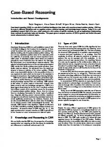
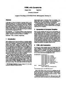
Figure 1: Mainboard with cards
2
Object Acquisition
Definitions: • Primitive: An Object that represents one of the following forms: cylinder, box, sphere, cone. • Part of a component: An object built from primitives, which on its own does not fulfil a useful function, e.g. a plate of a mainboard.
• Meta-Authoring Tool • Generic Authoring Tool • Configuration Tool These tools are explained in Section 2. Furthermore, in Section 3 the 3D-ObjAc (3D-Object Acquisition) object model,
• Component: An object built from parts of components, which is a constituent of a product, e.g. mainboard with sockets and slots. • Product: The totality of all components, e.g. a computer.
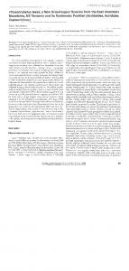
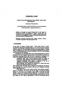
one after another or in parallel. In addition, the duration of positioning a component, can be defined. As it is often the case that products are not built in one piece but in segments we can also define intermediate steps. All components that have been produced earlier in the Authoring Tool for that domain can be selected. Once the configuration is finished a
Figure 3: Computer configuration
Figure 2: Creating an animation
The idea of object acquisition with GenAu-3D is to get different Authoring Tools for each domain. Within a domain certain products differ solely with respect to their colour or texture or are partly built from the same components. A Meta-Authoring Tool is used for predefining components or parts of components. From these predefined objects an Authoring Tool is created which can be used later to construct the final components. All components are identified unambiguously by the manufacturer and by their name. Furthermore additional infomation can be acquired, which can be presented later as part of the animation. In both tools components are approximated by primitive geometries. The following properties can be changed:
jar file is created that contains all component data and java classes necessary for the process of animation. This jar-file can either be started as an application or as an applet. In both cases an existing installation of a Java2 and Java3D1.2 runtime environment is required.
3
The Object Model
• Cylinder: height, radius, colour, texture
To acquire objects, a data format has been defined to describe all properties. It is based on XML and specified by a DTD. Not only shapes and colours should be captured by this object model. There is more information that has to be acquired i.e.: descriptions, position data, rotation data etc. In this section we will look at an example of how this data is stored. The excerpt listed below is produced by the Configuration Tool, but the other tools (Meta-Authoring Tool, Authoring Tool) generate similar output. In the next chapters the main features of this configuration file are discussed.
• Sphere: radius, colour, texture
3.1
• Cone: height, radius, colour, texture • Box: height, width, depth, colour, texture
In order to assemble the components in the animation contact points have to be defined in such a way that the position of one component to another is defined unambiguously. These contact points are described by position and rotation information. How to connect a component to another by means of these points is described in Section 4.5. After the components have been created an animation can be produced. The contact points, which have to match by name, provide a basis for this animation. Contact points which can be used in several animations are defined in the Authoring Tool, whereas contact points which are used only in one specific animation can be placed in the Configuration Tool. Here, also the order in which the components appear in the animation is defined. In case several components of the same type are on the same rank, they can be inserted
Object Information
In the first part of the file information about the object(s), included in the rest of the file, is given. A component needs a name and a manufacturer to identify it unambiguously. They are used in the Configuration Tool and the Animation Tool, which is created from the Configuration Tool. Furthermore, each component belongs to a domain specific Authoring Tool it is created from. An Authoring Tool contains groups to structure the domain it was created for. In the example in Figure 4 we would distinguish between the groups board, card, floppydrive and other hardware components a computer is assembled from. When using this component for an animation it is necessary to know when this component has to be inserted. This is done by the rankattribute. Furthermore it is possible to insert more than one component of the same type at this point of the animation,
COMPONENTNAME="P5A" MANUFACTURER="Asus" AUTHORINGTOOLNAME="Computer" COMPONENTGROUP="Board" RANK="4" NUMBER="2" TIME="1.0" INSERTIONTYPE="parallel" DESCRIPTIONAUTHOR="Peter B." DESCRIPTIONDATE="18.09.00" DESCRIPTIONURL="computer/board/asus/spx97v.dsc">
Figure 4: Object information section of an XML file Figure 6: Contact point section of an XML file e.g.: some screws. When animating the screws you can set the time in seconds they need to be inserted at their positions. If they are to be inserted in a complex structure it might be practical to enlarge the duration of an animion. This makes it easier to follow the animation. If there are more than one component at one rank in the Animation Tool they can be inserted simultaneously (parallel) or one after another (serial). After all, a component can be described. Therefore the name of the author who has written the description and the time the file at the specified URL has been created can be collected. This description is shown later in the Animation Tool.
3.2
Steps
Steps are only part of the description of an animation and are created in the Configuration Tool. They are used to Figure 5: Step section of an XML file create intermediate steps. In the example in Figure 5, part finished means that a section in the animation is over and a new part of the product will be created. As an alternative the value insert part would indicate that the part of the product, which as been removed in STEP2, will be inserted. This will give you the possibility to create some parts of the product and to fit them together later to the whole product.
3.3
Contact Points
Contact points are generated by the Authoring Tool and Configuration Tool and are needed for the animation. A component can contain more than one contact point, because a component can have relations to several other components. Consider a processor for example. It needs one contact point to be connected to the socket of the mainboard and another contact point for the fan, which is on top of the processor. A contact point for a socket is defined in Figure 6.
If the following condition is satisfied, two components can be interconnected: CONTACTNAME(A)== CONTACTNAME(B) & CONTACTTYPE(A) 6= CONTACTTYPE(B) & CONTACT(A)==free & CONTACT(B)==free The contact type is either male or female. Because products differ in their size contact points have to be represented in different sizes too. This is needed for better handling while creating them. A contact point is represented as an graphical object in the tools, but not in the final animations. It can be scaled by some fixed factors. UNIT describes the measure (mm, cm, m). Furthermore a contact point needs position data and rotation data. This data is responsible of the position a component has in relation to another component. Rotation and translation are to be interpreted relative to the origin of the local coordinate system the component is defined in. Figure 7: Primitive object section of an XML file
3.4
Primitive Objects
Primitive objects are the smallest visual entities, which are generated by the Meta-Authoring Tool and Authoring Tool. Every primitive object can be described as explained in Section 3.1. It consists of one of the following types: box, cone, sphere, cylinder. Dependent on this type the object for the scenegraph will be created. Because there is the possibility to create products of a wide range and different domains, there are different measures (mm,cm,m). Usually you define the size of a motherboard in centimeter and not in meter, which is the default unit in Java3D. The measure is used to get the factor the geometric data will scaled by. In the case of Figure 7: 2.0 ∗ 0.01, 1.0 ∗ 0.01, 1.0 ∗ 0.01. The information about the objects colour is stored by using the RGB colour model. To describe the appearance of a primitive object it is not only possible to use colours, furthermore you can choose pictures, which are used as textures for this object. These pictures can be found at the URLs specified in Figure 3.1. If a primitive object is part of a compound object it must have a description of its position and its rotation in this compound object. The rotation data is described in radian. If the primitive object is part of a compound object the position and rotation are relative to the origin of the local coordinate system of the compound object. Otherwise they are relative to the origin of the world coordinate system.
3.5
Compound Objects
A compound object is assembled of primitive objects. Every . . .
needed to create the 3D-objects, that are added to the scenegraph.
4
Scenegraph Management
In this section we look at the organisation of the data in the scenegraph. The scenegraph is created from the following units: • Primitive object • Compound object • Component Each unit is a subgraph itself. It provides different manipulation capabilities. The most important type mentioned above is the component. It combines primitive and compound objects. Additionally, it contains the contact points, which are responsible for the connection of the components as they are connected in reality. This means: If component A is connected to component B in reality then A is also connected to B in the scenegraph. This is very important, when several components are moved or rotated in the animation or should be moved or rotated by the user or another program. If there are cyclic relations in reality, one connection in the scenegraph can not be established, because scenegraphs in Java3D have to be acyclic. The remaining connections are sufficient, as will become apparent in Section 4.6.
4.1
Primitive Objects
Primitive objects appear to the user as cones, boxes, cylinders or spheres. These objects own certain properties, which can be changed by the user.
Figure 8: Compound object section of an XML file primitive object is constructed as shown in Section 3.4. The compound object has a name and a group attribute to identify it. This is for structuring the predefined objects, which can be used in the domain specific Authoring Tool. Furthermore, it contains the attributes to position and rotate the compound object. If the compound object is part of a component this information refers to the origin of the components local coordinate system. If it is used in the Authoring Tool, the data refers to the origin of the world coordinate system. Only files which are valid according to the DTD can be parsed. The parser will produce data objects, which contain all information about the components. This information is
Figure 9: Node representation of a primitive object
Figure 9 shows the scenegraph structure for primitive objects. Every primitive object can be added to the scenegraph or removed from it at any time. Thus, the first node is a
BranchGroup-Node, which can be detached from its parent node or may be added to it. The RotationTG-node below serves to rotate and to position this object. We provide an API to create and manipulate this node. The graphical object starts with the ObjectTG-node. It consists of the primitive itself and a selection box, which allow the user to highlight this primitive object. Primitive objects provide the following methods:
4.3
Contact Points
Contact points allow connecting several components according to their connections in reality. Consider the following example: A table consists of a table top and four table-legs. In the
• The colour of this object can be changed. • The spatial extension of this object can be changed. • If there is a light source, the object can be illuminated. • It is possible to texture the object. Additionally the texture can be enabled or disabled. This is important for positioning the contact points. • The object can be made transparent. This will also help the user to position the contact points for this component.
4.2
Compound Objects
A compound object is composed of several primitive objects. In the scenegraph it will be treated as a single object. This means, that you always remove or add the whole object, not single nodes. They own a more restricted set of properties than the primitive objects. The rotation data and the position data are manipulated the same way they were manipulated in the primitve objects.
Figure 11: Flat representation, less intuitive
scenegraph this can be represented by connecting the visual objects directly to the root node of this graph. The table top is positioned at the origin while the table-legs are positioned relative to the table top. So the table-legs are not connected to the table top, although they are connected to it in reality. This will make no difference for the viewer. But what will happen when moving the table top? In reality you will move the whole table. In this scenegraph this means to set the values of the TransformGroup-node the table top is attached to. Now it will make a difference to the viewer, because the table-legs stay on their old position, but not the table top. To achieve a motion for the whole table you have to set the values for the TransformGroup-nodes of the tablelegs as well, considering the motion of the table top. Now one can say: ”Insert a new TransformGroup-node, which has the legs and the top as its children and set the value of this node”. This will work in the example mentioned above. But what will happen when moving the table with its leg to a specified point in reality? In the scenegraph you have to add the position value of the leg to the target position value and assign this newly computed value to the TransformGroup-node of the table. This is really not intuitive. And it becomes even worse when manipulating components of more complex products by additionally rotating them. So it would be practical to have the possibility to map the physical connections in reality to the scenegraph. Contact
Figure 10: Node representation of a compound object
The compound objects also start with a Branchgroupnode as root and a RotationTG-node. The properties (light, texture, transparency, selectionbox) are propagated to the primitive objects. That means, the java-class which implements the compound objects contains a structure to administrate its primitive objects. This structure allows changing the properties of the primitive objects.
Figure 12: Contact point-representation, more intuitive
Figure 13: Node representation of a contact point
points will help us to achieve this. A contact point is built up in an easy way. It owns an ObjectBG-node, a ConnectTG-node and a ConnectBG-node. The ObjectBG-node is connected to the component the contact point is defined for. The ConnectBG-node is responsible for connections with other components. In that case the other component will be connected as child to the ConnectBG-node. Between the ObjectBG-node and the ConnectBG-node the ConnectTG-node is located. It contains the rotation and the position data of this contact point. Furthermore the contact point must have a description for its identification. Based on this identification it will be decided which components can be put together. If a contact point is in use it is declared occupied. The exact procedure how a connection is processed in the scenegraph will be described in Section 4.5.
4.4
Components
In addition to nodes, which represent the visual parts, components also contain nodes which are needed to control the animation. That means, that interpolators will manipulate different nodes of a component. Like the object types mentioned above, the components start with a BranchGroupnode. The nodes between the MotionTG-node and the ScaleTG-node are as follows. • MotionTG: This node contains the position of this component. The position interpolator uses this node to set the component to the right place. • RotationTG: Analogous to the MotionTG-node.
Figure 14: Node representation of a component
4.5
Connecting Components
Two components A and B are connected if the following holds: CONTACTNAME(A)= CONTACTNAME(B) & CONTACTTYPE(A) 6= CONTACTTYPE(B) & CONTACT(A)==free & CONTACT(B)==free and CONTACTTYPE is either male or female. Both contact points involved in this process will be declared occupied and will not be available for later connections. When unfixing B from A the contact points will be declared free. Alternatively, the contact point of B can be unfixed and B becomes child of its own contact point. This gives the possibility to connect the two contact points of A and B. Maybe
• OffsetTG: This node is important for connecting components. It will be explained in Section 4.5. • ScaleTG: Because the components will appear scaled in the upper area of the animation window, this node is used to scale them to their right size. Furthermore it is used by the scale interpolator to set them to their original size while animating them. The primitive objects and the compound objects as well as the contact points are children of the ObjectTG-node. A component owns three properties: • Lighting • Tranparency • Selection
Figure 15: Matching between two components
Figure 17: Matching
Figure 16: Connection of two components
this way is more esthetic than the other, but there is no practical advantage. Figure 15 and 16 show two components A, B. These are compressed representations of Figure 14. Only those nodes which are involved in the connection process and the state of the contact points are shown. First the contact points of both components are compared. If there are two contact points which fulfil the condition above, there is a match and these components can be connected (Figure 15). But you cannot connect them by making the matched contact point of B a child of the contact point of A. This will produce a MultipleParentException because the contact point of B is already connected to B itself. This could possibly lead to an cyclic scenegraph, which is not allowed. So we have to find another solution. To connect the components, the root-node of B (BG-node) is connected to (is child of) the contact point of A. The rotation information, which is contained in the ConnectTG-node of B’s contact point will be stored negated in the RotationTG-node as well as the translation information is stored negated in OffsetTGnode. This will set the contact point of B to the origin of the local coordinate system with x-,y- and z-rotation equal to zero. Now the component has the right place and the right rotation and can become a child of A.
4.6
Connecting Parts of Products
The way of connecting components mentioned above is the basis of connecting parts of products. To repeat the meaning of ”parts of products”: they are built up of several components. The problem of connecting them is comparable with the table-problem depicted in Section 4.3. The solution of this problem is based on contact points. These points make it possible to exchange every component, which is a child of another component, with its parent. But what is the advantage? The advantage is that every component can be made root of a subgraph. And that will allow us to move or to rotate every component without changing its appearance while at the same time maintaining all connections which exist in reality.
Figure 18: Rearrangement
/*detach the old child from its parent*/ newParent.detach(); /*append the old parent to its old child, see Figure 16*/ newParent.addChild(newChild); i++; } . . • Connection: The new root-node will be appended to the component of part B.
5
The Animation
The object types and the way the scenegraph can be modified allow us to build an animation which will demonstrate how a product is built up of its components.
Figure 19: Component connection
The process can be seen in Figures 17, 18, 19 and performs the following four steps. • Matching: Find out the contact points that match and the components they belong to. • Path detection: This will retrieve a path from the part of the product, which contains the component that should be a new child of a component in the other part of the product(part B). This path contains all components from the one that is matching to the root of this part. The path ist stored in an array (pathComponents[]), whose first element is the root-node. • Rearrangement: The scenegraph of part A is rearranged with the matching component as its root. Description of this process: . . i=0; while(i+1 < pathComponents.length) { /*get the parent, that will be a child in the newly arranged graph */ newChild = pathComponents[i]; /*vice versa*/ newParent = pathComponents[i+1];
Figure 20: Animation with intermediate step
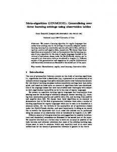
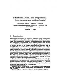
The upper part of the rendering window contains the components in the order they are needed for the animation. If there are intermediate steps, the corresponding parts of the product are shown in the lower part of this window and can be reused if they are needed in the sequel of the animation. Steps are also shown in the control panel. They are marked
Figure 21: Animation of interconnecting a processor with a socket
with blue coloured list entries. The interpolators needed for the animation of every component are bound dynamically to these components. A short description of the elements of the control panel: • List: The list in the upper part of the control panel shows the components in the order they are inserted. If all components of one rank are used, this entry is coloured red. If there are more than one component at one rank the number in the entry shows the remaining components. • Light: The light button switches the light on or off. • Product description: This button will open a text area with the description of the whole product. • Component description: This button will open a text area with the description of the components as they are inserted. Another possibility is to click on the components to show the information for this component. • Front-view: This button will always position the work place in front of the viewer. • Background color: This button gives the possibility to change the colour of the work space. • Animation control buttons: These buttons control the direction and the mode of the animation (controlled by the user or automatically) • Slider: With the help of the slider the user can control the animation speed.
6
Conclusion and future work
In this paper we discussed how components can be built up from primitive objects and how they are supplied with contact points. These contact points are responsible for composing single components to form the whole product. This is done by declaring components as single units in the scenegraph and by using contact points to reorder components without changing the appearance and while at the same time maintainig the connections, which exist in reality. All components are described via an XML based data format. One possibilty to use this object model described by XML-files is the construction of animations. But it would also be possible to develop other applications in the area of e-commerce.
Improvements are always possible. So the next step is to allow the user of GenAu-3D to define free formed objects or to use objects, which already exist. Applications and applets can be found on the internet at: http://www.cs.uni-sb.de/RW/users/pblanche /genau3d/genau3d.html
References [1] Dennis J. Bouvier, Java 3D API Tutorial Updated, Sun Microsystems, 1999 [2] Mathias Nousch, Bernhard Jung, CAD on the World Wide Web: Virtual Assembly of Furniture with BEAVER. VRML 99, Fourth Symposium on the Virtual Reality Modeling Language, Paderborn, Germany, 1999, p.113-119 [3] Erik Wilde, WWW-Grundlagen und Technologie, Extensible Markup Language (XML). http://dret.net/lectures/www-ss00/xml.pdf, ETH Z¨ urich, 2000 [4] Reenschhaus: http://www.business3d.de/reensch/ reensch1024.html
Figure 21: Animation of interconnecting a processor with a socket
A Framework for Component Based Model Acquisition and Presentation Using Java3D Peter Blanchebarbe
Stephan Diehl