Journal of Engineering Design, Vol. 10, No. 3, 1999
A Framework for Design Process Speci® cations Management
ALI A. YASSINE & DONALD R. FALKENBURG
SUMMARY Major con¯ icts in design process management seem to stem from speci® cation con¯ icts among the constituent coupled design tasks. Coupled tasks represent con¯ icts in the ¯ ow of information of a design process. Resolving these speci® cation con¯ icts early on in the development process tends to reduce product development lead times and cost. In this paper, we attempt to explain the coupling or interdependency in design tasks by the speci® cations imposed on these tasks. Then, we formulate the fundamental equations necessary for engineering speci® cation management and devise a graphical tool for design process improvement. The major hypothesis investigated is that any two coupled tasks can be de-coupled if the speci® cation of one task can be designed to absorb a certain percentage of any possible variation in the output of the other task.
1. Introduction Concurrent product design and development (or concurrent engineering) is an attempt to incorporate various constraints and requirements, related to the product life cycle, in the early design stages [1± 3]. This approach tends to improve the product quality and reduce the product development lead-time and manufacturing costs [4]. However, due to concurrent consideration of many factors, the relationships and dependencies between some design tasks may be violated (i.e. tasks that are inherently sequential are performed concurrently). This will increase the complexity of the design process and make it more diý cult to manage [2]. Most of the research in concurrent product development management is divided into two main streams. First, research oriented towards the improvement of methods and tools that extract product speci® cations from a set of customer requirements (i.e. QFD and its derivatives) [1]. Second, research devoted to the performance improvement of the design and development process given a set of product speci® cations to be satis® ed [2,5,6,7± 9]. Relatively little research attention seems to be oriented towards the process of managing design task speci® cations once these are attained. Major con¯ icts in design process management stem from speci® cation con¯ icts among the constituent design tasks. Resolving these speci® cation con¯ icts early on in the development process is essential for successful concurrent engineering implementations. The study of task speci® cations (i.e. tolerances) is not a new concept. The literature Ali A. Yassine Massachusetts Institute of Technology, Center for Technology, Policy and Industrial Development, Cambridge, MA 02139, USA. E-mail:
[email protected]. Donald R. Falkenburg, Wayne State University, Industrial and Manufacturing Engineering, Detroit, MI 48202, USA. ISSN 0954-4828 (print)/ISSN 1466-1837 (online)/99/030223-12
1999 Taylor & Francis Ltd
224
A. A. Yassine & D. R. Falkenburg
is full of articles discussing models and techniques of tolerance analysis, allocation and computer-aided tolerancing [10± 13]. The majority of these studies address the tolerancing problem from a minimum manufacturing cost perspective [21]. Another major technique that gained a lot of attention in the area of quality engineering is Taguchi’ s tolerance design [14,15]. The Taguchi method calls for statistically determining the components that have a large contribution to the variance of a measured quality characteristic and imposing tight tolerances on them. Suh [16] took a completely diþ erent approach to tolerancing through his axiomatic design principles. He discusses the relationship between the tolerances imposed on the functional requirements (FRs) of a design and the coupling of the design. Our research, described in this paper, builds on the work of Suh [16] and Steward [17,18] that is introduced in the next section. Coupled tasks represent con¯ icts in the ¯ ow of information of a design process. Resolving such con¯ icts requires engineers to iterate through trial designs until an agreement is reached. Therefore, coupled tasks are mainly responsible for design process iterations. Managing design process iterations inevitably lead us to investigate the management of task speci® cations. This paper presents a methodology to maximize design process concurrence through a better understanding of design task speci® cations. We attempt to explain the coupling or interdependency in design tasks by the speci® cations imposed on these tasks. The rest of the paper proceeds as follows. In Sections 2± 4, we introduce Steward’ s [17,18] work on design structure management, Suh’s [16] work on axiomatic design, and combine them through a sensitivity design structure matrix (SDSM) representation. In Section 5, we introduce our new concept of speci® cation management and lay down the fundamental equations. A simple example is presented in Section 6 to familiarize the reader with the application of the new method. A generalized graphical solution, for de-coupling two coupled tasks, is then proposed in Section 7. Finally, in Section 8, we present a summary and some concluding remarks. 2. The Design Structure Matrix Steward [17,18] developed the design structure matrix (DSM) as a tool to represent and analyze task dependencies of a design project. The DSM is a binary square matrix with m rows and columns, and n non-zero elements, where m is the number of design tasks and n is the number of information ¯ ows (or dependencies) going from one design task to the other. If there exists an information dependency from task i to task j, then the value of element ij (column i, row j) is unity (or marked with an X). Otherwise, the value of the element is zero (or left empty). If one interprets the task ordering, in the matrix, as a time sequence, then marks below the diagonal represent information transferred to later tasks, and marks above the diagonal depict information fed back to earlier tasks. Feedback marks represent a diý cult situation for engineering design managers because they imply that upstream tasks require information from downstream tasks. In an attempt to eliminate such marks, tasks within the DSM are rearranged such that the ¯ ow of information will be solely in the forward direction. This process of task rearrangement is called partitioning. Several partitioning algorithms have been cited in the literature; however, a discussion of partitioning algorithms is outside the scope of this paper. The interested reader can be referred to Refs. [2,17± 19]. Three diþ erent task dependencies (i.e. relationships) can be readily observed when inspecting a partitioned DSM: sequential tasks, parallel tasks and coupled tasks. A task is part of a sequential group if its row contains a mark just below the diagonal. Two or
Design Process Speci® cations Management
225
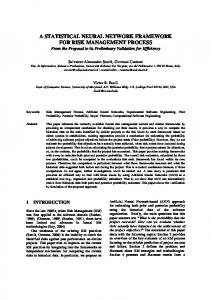
FIG. 1. Simpli® ed DSM for the Kodak Cheetah project (source: Ulrich & Eppinger [20]). more tasks are parallel if there are no marks linking them. Finally, two or more tasks are coupled if there is no ordering of the DSM that will render the matrix lower triangular. Therefore, the existence of a mark above the diagonal, after partitioning the DSM, indicates coupling between tasks [19]. A sample DSM with the three diþ erent types of relationship is shown in Fig. 1. Note that tasks B and C are considered sequential, tasks D and E are parallel, and tasks G, H and I are coupled. The DSM representation was used and proved, by several researchers [2,18,19], to be a useful tool in concurrent engineering management and implementation. Its ability to display all the design steps involved in the design process, allowing for direct coupling between them, in a compact form is the basic strength of this tool. 3. Axiomatic Design and the Design Matrix Suh [16] describes the design process as the mapping between the FRs, in the functional domain, and the design parameters (DPs), in the physical domain. The FRs are de® ned as the minimum set of independent requirements that completely characterize the functional needs of the product. The DPs are the key variables that characterize the physical entity created by the design process to ful® ll the FRs [16]. The design matrix (DM) relates a component of the FR vector to a component of the DP vector [19]. The mapping between a given FR vector and a DP vector having a design matrix [A] is given by the design equation as: {FR} 5
[A]{DP}
(1)
For the two-dimentional case, [A] may be represented as: [A] 5
[ ] A11 A12 A21 A22
(2)
In general, the elements of the DM may be expressed by: Aij 5 FRi / DPj . Analysis of the DM, as described by Suh [16], is extremely useful in establishing the characteristics of a `good’ design. That is, a designer will be able to discriminate between a good
226
A. A. Yassine & D. R. Falkenburg
design and a bad one by inspecting and comparing the diþ erent DMs corresponding to the diþ erent design alternatives. According to Suh [16], a design is coupled if it violates design Axiom 1. Axiom 1 states that for an uncoupled design, each FR is strictly satis® ed/mapped to one DP. That is, a change in one FR cannot be accomplished by simply changing the corresponding DP. Changing one DP will aþ ect more than one FR. Simply stated, Axiom 1 describes an optimal design as that which maintains the independence of FRs. In order to do so, the design activities that constitute this design process must, then, be uncoupled. It is worth noting that a diagonal DM represents an uncoupled design, while a DM containing non-diagonal elements represents a coupled design. Suh [16] suggests that a coupled design may be de-coupled by rendering the DM lower triangular. In doing so, we will be able to adjust the DPs in a particular order; thus, satisfying Axiom 1.
4. The Sensitivity Design Structure Matrix (SDSM) Steward’s [17,18] DSM is diþ erent from Suh’ s [16] DM in that it describes the system only in the physical domain and it relates the DPs to each other. Therefore, Suh’ s uncoupled diagonal DM becomes a 0 DSM. In addition, Suh [16] recommends that we seek a de-coupled design if an uncoupled one does not exist. A de-coupled design is a design solution where the DM is a triangular matrix. This description of a decoupled design is in agreement with Steward’s partitioning algorithm that seeks a lower triangular form of the DSM. The SDSM is a link between Suh’ s axiomatic approach to design and Steward’ s representation of design process dependency. The oþ -diagonal entries, of a SDSM, in row i and column j represent the partial derivative for the output of task i to the output of task j: Oi / Oj . Extending the classical DSM representation by the inclusion of the sensitivity coeý cients allows us to understand and capture the design process task interactions more accurately (as compared with the binary DSM). The improved DSM representation allows us to investigate a new approach for improving the design process; namely, management of task speci® cations, as will be discussed in the rest of this paper. In order to evaluate the partial derivatives, we need to be able to express the system and its tasks analytically, i.e. in terms of mathematical expressions. In fact, we are seldom able to express complex engineering systems and the interaction among its subsystems and components analytically. Often, these relationships are not known and must be determined experimentally [16]. Classical statistical design of experiments [21] or Taguchi’s approach [14,15] can be used to de® ne polynomial relationships between independently varied parameters and measured outputs, therefore experimentally de® ning sensitivities between the tasks.
5. A Framework for Design Speci® cations Management A speci® cation hierarchy is a map showing the impact of a change in the speci® cations of a task, in the design process, on other tasks within the same design process. Inspecting the DSM and tracing the marks associated with a certain task develops this hierarchy. Any disturbance or change in the speci® cation at one point in the design network will be propagated through the speci® cation hierarchy and impact downstream tasks. The eþ ect of the disturbance can be tolerated if the task is independent of the excited task or if the downstream task speci® cation can absorb it. Evaluating the partial derivatives
Design Process Speci® cations Management
227
of these tasks determines whether the later condition exists. Therefore, the SDSM serves both purposes of developing the hierarchy and investigating task sensitivities. The ® rst step in speci® cation management is to determine the contribution of each feedback mark (in the DSM) to the output of a certain task impacted by these feedback marks. In order to select the principal feedback marks that dominate the output of a task i, the variance r 2i of Oi can be determined by varying the output of all the tasks representing these feedback marks (i.e. Oj values). The Oj that gives the largest value of r 2i has the largest eþ ect on Oi and, hence, is the dominant (i.e. principal) feedback mark [16]. For the feedback marks that contribute only a small amount to the task’s output, consider de-coupling the two tasks by allowing wider speci® cation limits on the dependent task. For input streams that contribute a large amount to the output of a task, consider virtually de-coupling the two tasks. Two coupled tasks A and B are virtually de-coupled if the speci® cation of task A is designed to absorb a certain percentage (say 95%) of any possible variation in the output of task B, and vice versa. 5.1 A Motivational Example Although tasks in real product development processes can be complex, consider a simple example where task A depends on three other tasks. In this example, task A receives design information, from its predecessors, about parameters X1 , X2 and X3 . Task A performs its analysis using function Z 5 0.01(X1 ) + 100(X2 ) + 20(X3 ) and delivers the design parameter Z to its successors. Clearly, task A is most sensitive to changes in X2 and least sensitive to changes in X1 because Z Z Z < < . X1 X3 X2 If the teams computing values for X2 and X3 can accomplish their job in 1 week, but the team responsible for computing X1 will take 3 weeks to accomplish this task, then is it important to wait for the input from team 1? There is no simple answer for this question; however, if we can establish a range of values for X1 , we can begin to answer the question. Assuming that, based on similar design experiences, X1 is known to be uniformly distributed between 1000 and 1002, then Z 5 0.01E(X1 ) + 100(X2 ) + 20(X3 )6 error. E(X1 ) is the expected value of X1 and the error term is equal to Z D X1 5 X1 2
0.01
(1002 2
1000) 2
5
0.01.
If the error term lies within the speci® cation of task A, then task A can de® nitely proceed without precise information on X1 design data. On the other hand, if the speci® cation of task A is smaller than the error term, then there is a chance that task A will be repeated due to the approximation of the value of X1 . Fig. 2 shows the relation between the error and speci® cation probability distributions, where the shaded area represents the resultant repetition probability. 5.2 Representation of a Design Task At the lowest level of detail, an engineering design process is divisible into a number (usually large) of individual design tasks that collectively de® ne a complete project/ product [2,17,18]. Each task is de® ned by a speci® cation S. Speci® cations are usually
228
A. A. Yassine & D. R. Falkenburg
FIG. 2. Probability of task A repetition assuming a rectangular speci® cation distribution.
given as nominal values plus/minus a tolerance value. In order to perform the task, an input I is required. There are two types of inputs: design variables (or controllable input) and interface variables (or uncontrollable input). Design variables are the output of the task itself. Furthermore, they can be decided and varied by the task itself. The interface variables constitute the outputs of some other tasks. The result of the task is an output O, which is a function of both design and interface variables. The performance X is a measure of the conformance of the output to the speci® cation. Namely, it is the probability that a task’s output falls within the speci® ed speci® cation limits for that task. A block diagram representation of a task is shown in Fig. 3 with the four diþ erent
FIG. 3. Block diagram of a task.
Design Process Speci® cations Management
229
attributes that characterize any task. Interface variables ensure that certain decisions are reached in conjunction with previous decisions, and are subject to change based on later results. In particular, further analysis may show that any previous decision is unworkable and needs to be redone. It is important to distinguish between the input of a task (I) and its speci® cation (S). Inputs are information supplied to the task based on its request: they could be a parameter, a document, a computer-aided design drawing, or a process/product data. On the other hand, speci® cations are constraints imposed on the design task and they represent the bounds on a feasible solution. Task speci® cations could be time or cost limitations, space constraints or power/torque requirements.
5.3 Basic Notation If a set of tasks j feed task i, then the output of task i is dependent on its input (Ii ) and the outputs of tasks j(Oj ): Oi 5
f(Ii , Oj )
(3)
The change in Oi is explained by: D Oi 5
Oi D Ii + Ii
R
; j
Oi D Oj Oj
(4)
An optimal design (i.e. uncoupled) is a design solution where the change in the output of task i(Oi ) is only explained by changes in Ii , thus forcing the second term of the right-hand side of equation (4) to be equal to zero, as in equation (5).
R
; j
Oi D Oj 5 Oj
0
(5)
There are four diþ erent design scenarios that satisfy equation (5). (1) A design environment where D Oj is always zero. That is, there is no uncertainty or changes in the values of Oj throughout the whole design process. This situation is referred to as a static design environment. (2) The determination of a design (Oi ) such that the sensitivity of Oi with respect to Oj (; j) is zero, as in equation (6). This is referred to as an uncoupled design. If two tasks i and j satisfy equation (6), then the two tasks are said to be uncoupled. Satisfying equation (6) is a purely design issue, where the system is designed in such a way that its components do not interact or in¯ uence (i.e. are independent of ) each other. This is in agreement with Suh’s [16] Axiom 1 describing an optimal design as an uncoupled one where the design tasks are completely independent from each other. Oi 5 Oj
0, ; j
(6)
(3) In the absence of a design luxury allowing us to utilize equation (6), a designer must seek a de-coupled design where the design tasks are weakly dependent on each other. The designer seeks a design (Oi ) such that variations in Oj are
230
A. A. Yassine & D. R. Falkenburg absorbed by the speci® cation of task i, as in equation (7). This is referred to as a de-coupled design where task i is weakly dependent on a set of tasks j. LSLi
465 rejects. 0