coverage and area, delay and power consumption. Table 1. ..... coverage. Map with fault probabilities. Annotate HDL with TMR. P&R. No. Evaluate. Yes.
A Framework for Enabling Fault Tolerance in Reconfigurable Architectures Kostas Siozios1 , Dimitrios Soudris1 and Dionisios Pnevmatikatos2 1
School of Elect. & Computer Eng., National Technical University of Athens, Greece Electronic & Computer Eng. Department, Technical University of Crete, Greece
2
Abstract. Fault tolerance is a pre-request not only for safety critical systems, but almost for the majority of applications. However, the additional hardware elements impose performance degradation. In this paper we propose a software-supported methodology for protecting reconfigurable architectures against Single Event Upsets (SEUs), even if the target device is not aware about this feature. This methodology initially predicts areas of the target architecture where faults are most possible to occur and then inserts selectively redundancy only there. Based on experimental results, we show that our proposed selectively fault-tolerance results to a better tradeoff between desired level of reliability and area, delay, power overhead.
1
Introduction
SRAM-based Field-Programmable Gate Arrays (FPGAs) are arrays of Configurable Logic Blocks (CLBs) and programmable interconnect resources, surrounded by programmable input/output pads on the periphery. Even though their programmability feature makes them suitable for widely application implementation, a number of design issues have to be tackled. Among others, reliability issue becomes worse as devices have evolved. For instance, as the transistor geometry and core voltages decrease, while the numbers of transistors per chip and the switching frequency increase, the target architectures become more susceptible to incur faults (i.e., flipped bit or a transient within a combinatorial logic path). Consequently, mechanisms that handle faults detection and correction during device operation are required, even for non critical safety systems. The last ten years many discussions were done about the design of reliable architectures with fault tolerant features. More specifically, the term fault tolerant corresponds to a design which is able to continue operation, possibly at a reduced level, rather than failing completely, when some part of the system fails [1, 3, 4, 5, 6, 8, 9, 10, 11, 12, 13, 14]. These solutions include fabrication process-based techniques (i.e. epitaxial CMOS processes) [10], design-based techniques (i.e. hardware replicas, time redundancy, error detection coding, selfchecker techniques) [4], mitigation techniques (i.e. multiple redundancy with voting, error detection and correction coding) [5], and recovery techniques (i.e. reconfiguration scrubbing, partial configuration, rerouting design) [11].
Even though fault tolerance is a well known technique, up to now it was mostly studied for ASIC designs. However FPGAs poses new constraints (i.e. higher power density, more logic and interconnection resources, etc), while the existing fault models are not necessarily applicable. To make matters worse, faults in FPGAs can alter the design, not just user data. In addition to that, the FPGA designs utilize only a subset of the fabricated resources, and hence only a subset of the occurred faults may result to faulty operation. Consequently, FPGA-specific mitigation techniques are required, that can provide a reasonable balance among the desired fault prevention, the performance degradation, the power consumption and the area overhead due to the additional hardware. Up to now there are two approaches for preventing faults occurring on FPGAs. The first of them deals with the design of new hardware elements which are fault tolerant enabled [2, 4, 12, 15]. These resources can either replace existing hardware blocks in FPGAs, or new architectures can be designed to improve robustness. On the other hand, it is possible to use an existing FPGA device and provide the fault tolerance at higher level with CAD tools [2, 3, 4, 8, 13, 14]. Both of these approaches have advantages and disadvantages, which need to be carefully concerned. More specifically, the first approach results to a more complex architecture design, while the derived FPGA provides a static (i.e. defined at design time) fault tolerant mechanism. On the other hand, the implementations belonging on second approach potentially are able to combine the required dependability level, offered by fault tolerant architectures, with the low cost of commodity devices. However, this scenario imposes that the designer is responsible for protecting his/her own design. In [12] a fault tolerant interconnection structure is discussed, where the faults are corrected by spare routing channels which are not used during place and route (P&R). A similar work is discussed in [13], where a defect map is taken as input to P&R tool and then application’s functionalities are not placed in the faulty blocks. In another approach [14], EDA tools take as input a generic defect map (which may be different from the real defect map of the chip) and generate a P&R according to this. A work that deals with a yield enhancement scheme based on the usage of spare interconnect resources in each routing channel in order to tolerate functional faults, is discussed in [15]. The only known commercial approach for supporting fault tolerance in FPGAs can be found in [8]. This implementation inserts two replica blocks for each of the application’s logic blocks, which are working in parallel, while the output is derived by comparing their outputs with a majority voting. Table 1 gives a qualitative comparison in terms of supported features for a number of fault tolerant approaches found in relevant references. In this paper we propose a software supported methodology that improves application’s reliability, without inserting excessive amount of redundancy over the entire FPGA architecture. More specifically, we identify sensitive sub-circuits (where faults are most possible to occur) and we apply the proposed fault tolerant technique only at these critical regions rather than inserting redundancy in the
entire device. Such an approach results to better tradeoff between desired fault coverage and area, delay and power consumption. Table 1. Qualitative comparison among fault tolerant approaches. Feature Fault tolerant Protects Modifies Applied uniformly
[8] TMR
[12] Spare routing Logic Routing HDL Hardware Yes Yes
[13] Defect map Logic HDL No
[14] [15] Proposed Defect Spare TMR & map routing fault map Logic Routing Logic HDL Hardware HDL No Yes No
Online fault management
No
No
No
No
No
Yes
Multiple fault tolerant techniques Software support Public available Complete framework
No Yes No Yes
No No No No
Yes Yes No No
No Yes No No
No No No No
Yes Yes Yes Yes
The main contributions of this paper are summarized, as follows: 1. We introduce a novel methodology for supporting on-line fault detection and correction for FPGA devices. 2. We identify sensitive sub-circuits (where faults are most possible to occur) and we apply the proposed fault tolerant technique only at these points, rather than inserting redundancy in the entire device. 3. We developed a tool that automates the introduction of redundancy into certain portions of an HDL design. 4. The derived application implementations are validated with a new platform simulator. The rest paper is organized as follows: In section 2 we discuss the motivation of this paper, while section 3 describes the implemented fault tolerant technique. The proposed methodology, as well as its evaluation is discussed in detail in sections 4 and 5, respectively. Finally, conclusions are summarized in section 6.
2
Motivation
The source of errors in ICs can be traced to three main categories: (i) due to internal to the component (i.e. component failure, damage to equipment, cross-talk on wires), (ii) generally external causes (i.e. lightning disturbances, radiation effects, electromagnetic fields), and (iii) either internal or external (i.e. power disturbances, various kinds of electrical noise). Classifying the source of the disturbance is useful in order to minimize its strength, decrease its frequency of occurrence, or change its other characteristics to make it less disturbing to the hardware component.
The first step in order to build a reliable system is to identify possible regions with increased probability of failure. Throughout this paper we study faults related to power, thermal, as well as random effects. More specifically, the increased switching activity results to higher power consumption and consequently to higher on-chip temperatures. In [17], Black mentioned that the mean time to failure (M T T F ) of aluminum interconnects exponentially decreases as the temperature (T ) of a chip increases. Equation 1 gives the mathematical expression that describes this phenomenon. Ea
MTTF ∝
e kT n Jdc
(1)
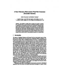
where Ea is the enable energy (its value is defined experimentally), Jdc denotes the threshold of electromigration current, while n and k are constants. The switching activity of an application is a property which does not depend either to the target platform, or the employed toolset that performs application mapping. However, the employed toolset introduce some constraints regarding the spatial distribution of regions with excessive high (or low) values and consequently with increased (or decreased) probability of failure [18]. Regarding the random faults, they exhibit a distribution of independent (non-correlated) failures. By combining the spatial variation of these values of the three parameters over the FPGA device, we are able to identify regions with increased failure probability. In order to show that different applications result to different distributions of failure probabilities (even for the same P&R algorithms), Fig.1 plots this variation over an 64×64 FPGA array regarding the s298 and frisc benchmarks, without considering yet any redundancy. In this figure, different colors denote different failure probabilities, while as closer to red color a region is, the higher probability for this region to occur a fault.
60
60
50
50
40
40
30
30
20
20
10
10
10
20
30
40
50
60
10
20
(a)
Reduced failure probability
0%
30
40
50
60
(b) 20%
40%
60%
80%
100%
Increased failure probability
Fig. 1. Spatial distribution of failure probability for (a) s298 and (b) frisc benchmarks.
Based on these maps, it is evident that the failure probability is not constant across the FPGA or among different applications, since it varies between two arbitrary points (x1 ,y1 ) and (x2 ,y2 ) of device. Based on this distribution it is feasible to determine regions on the device with excessive high values of failure probability (regions of importance), where we have to pay effort in order to increase the fault tolerance. Consequently, the challenge, with which a designer is faced up, is to choose only the actually needed redundancy level, considering the associated spatial information from the distribution graph. A second important conclusion is drawn from Fig.1: although the majority of existing fault tolerant techniques exhibits a homogeneous and regular structure, the actually critical for failure resources provide a non − homogeneous and irregular picture. Consequently, careful analysis of the points of failure must be performed, while the target system implementation needs to combine regions with different density of fault tolerance.
3
Proposed Fault Tolerant Technique
Our target is a generic recent FPGA device similar to the Xilinx Virtex architecture, consisting of an array of configurable logic blocks (CLBs), memories, DSP cores and programmable input and output blocks (placed on its periphery). We assume that the logic blocks are formed by a number of Basic Logic Elements (BLEs), each of which is composed of a set of programmable Look-Up Tables (LUTs), multiplexers, and flip-flops. The communication among these hardware blocks is provided by a hierarchical interconnection network of fast and versatile routing resources. More info regarding the architecture of target FPGA can be found in [19]. In order to provide fault tolerance, we incorporate an R-fold modular redundancy (RMR) technique. Such a mechanism can effectively mask faults if only less than ((R + 1)/2) replicas are faulty (either on combinational and sequential logic), but the faults present in different register locations and the voter works properly. This approach was first studied by J. Neumann [16], while the only commercial software product [8] for supporting fault tolerance in FPGAs is also based on this technique. The main advantages of incorporating an RMR-based technique are summarized, as follows: (i ) the corrective action is immediate, since the faulty module never affects the circuit, (ii ) there is no need for fault detection procedures, and (iii ) the conversion of a non-redundant system to a redundant one is easily undertaken without hardware modifications. On the other hand, this approach cannot recover faults occurred on routing fabric. If these faults are also required to be detected and repaired, another technique (usually based on spare routing resources) must be incorporated in conjunction. At the RMR-based technique, the reconfigurable platform is encoded as a M -of-N system, consisting of N hardware blocks where at least M (M