locally managed, distributable objects ..... ViewPoints VPS and VPD exist, then there should be a relationship ... specification in the ViewPoint, VPS, created from.
A Framework for Expressing the Relationships Between Multiple Views in Requirements Specification Bashar Nuseibeh
Jeff Kramer
Anthony Finkelstein
Department of Computing, Imperial College 180 Queen’s Gate, London, SW7 2BZ, UK Email: {ban, jk, acwf}@doc.ic.ac.uk.
Abstract †
sufficient for their development. This is particularly true of the requirements engineering phase of the software development life-cycle. Requirements engineering encompasses activities ranging from requirements analysis and elicitation to specification, conflict resolution and validation. Even a single activity such as requirements elicitation, is likely to involve multiple development participants who will hold multiple perspectives on a single domain. This heterogeneity of representations and processes poses challenging research problems of integration: (1) the integration of the methods used to specify system requirements, (2) the integration of the tools that support these methods, and (3) the integration of the multiple specification fragments produced by applying these methods and tools. By explicitly deploying “views” that encapsulate partial specifications together with the development techniques by which they are produced, a framework is in place within which the problems of integration outlined above may be addressed. However, the difficulties of expressing, invoking and applying the relationships between multiple views need to be resolved, before integration in this setting may be achieved.
Composite systems are generally comprised of heterogeneous components whose specifications are developed by many development participants. The requirements of such systems are invariably elicited from multiple perspectives which overlap, complement and contradict each other. Furthermore, these requirements are generally developed and specified using multiple methods and notations respectively. It is therefore necessary to express and check the relationships between the resultant specification fragments. In this paper we deploy multiple “ViewPoints” that hold partial requirements specifications, described and developed using different representation schemes and development strategies. We discuss the notion of interViewPoint communication in the context of this ViewPoints framework, and propose a general model for ViewPoint interaction and integration. We elaborate on some of the requirements for expressing and enacting inter-ViewPoint relationships - the vehicles for consistency checking and inconsistency management. Finally, while we use simple fragments of the requirements specification method CORE to illustrate various components of our work, we also outline a number of larger case studies that we have used to validate our framework. Our computer-based ViewPoints support environment, The Viewer, is also briefly described
1.
1.2. Views in Requirements Engineering
Introduction
Views are vehicles for separation of concerns. They allow development participants to address only those concerns or criteria that are of interest, ignoring others that are unrelated. In our earlier work [23], we have used the term “multiple perspectives problem” to describe the class of problems surrounding the development of composite systems [18] by many development
1.1. Motivation
Heterogeneity is inevitable in most composite systems of significant size, and no single development process and representation will be † IEEE Transactions on Software Engineering, October 1994.
-1-
participants who deploy sundry representation schemes, use a variety of development strategies and hold diverse domain knowledge. We have also proposed an object-based framework deploying “ViewPoints” within which the above problems may be tackled. ViewPoints in our framework serve to separate the concerns of different developers and the different development techniques and notations that these participants employ. The term “viewpoint” has been defined and deployed in a variety of settings in software engineering, particularly in the domain of requirements engineering. For example, in Structured Analysis [50] a viewpoint expresses an interest in some aspect of a system, while in CORE [42] it represents any information processing entity. Kotonya and Sommerville [31] treat viewpoints as service recipients, whereas Ainsworth et al. [2] regard them as formal partial specifications. Leite makes a further distinction between “views”, “perspectives” and “viewpoints”, and proposes a technique for the early validation of viewpoint-based requirements, termed “viewpoint resolution” [36]. The ViewPoints framework described in this paper, generalises the notion of a “viewpoint” to facilitate its manipulation in composite system development. ViewPoints in this framework draw together the notion of an “actor”, “knowledge source”, “role” or “agent” with the notion of a “view” or “perspective” held by the former. As such, the framework is organisational - facilitating separation of concerns and the structuring of software development knowledge.
inter-ViewPoint communication as a vehicle for ViewPoint integration. The ViewPoint interaction model we present straddles both the method construction stage during which inter-ViewPoint relationships are expressed, and the method application stage during which these relationships are enacted (invoked and checked). We illustrate the model by constructing part of the requirements specification method CORE † [42, 43], and applying it to specify a simple problem. We argue that successful inter-ViewPoint communication - guided by a model of the development process - holds the key to achieving integration in a heterogeneous, possibly distributed, setting. Thus, there is a need to express relationships between ViewPoints, enact these relationships (e.g., check consistency and transfer information), and resolve conflicts (if and when it is necessary to do so). Although we examine the application of ViewPoints for requirements specification, we further argue that requirements engineering from multiple perspectives, multiparadigm specification [63] and multiparadigm programming [40, 62], are all facets of the same generic (multiple perspectives) problem. We begin by presenting an overview of the ViewPoints framework emphasising its organisational nature and decentralised architecture. The next section describes the method engineering process within the ViewPoint framework, which is followed by an account of how requirements methods are used to develop requirements specifications in this context. A model of ViewPoint interaction is then presented and illustrated using the simple examples introduced in the preceding two sections. A review of our experiences in using the framework and associated interaction model are then described, which includes and account of case studies and automated tool support that we have developed and used, respectively, to validate our approach. Finally, overlapping and related research work is presented, some conclusions are drawn, and an agenda for further research is outlined.
1.3. Scope of Paper
Michael Jackson accurately points out that “... having divided to conquer, we must reunite to rule.” [29]. In other words, having decomposed a system into different components (ViewPoints), it is then necessary to achieve some level of integration between these components. To integrate multiple requirements specification ViewPoints, overlaps must be identified, complementary participants made to interact and cooperate, and contradictions resolved. In this paper, we address the notion of
† Since CORE uses the term “viewpoint” as part of its terminology, we substitute the term “agent” in its place to avoid the clash in nomenclature.
-2-
STYLE = notation
Representation Knowledge
WORK PLAN = development actions, strategy and process
Development Process Knowledge
DOMAIN = area of concern SPECIFICATION = partial system description
Specification Knowledge
WORK RECORD = development history
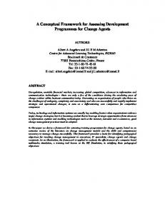
Fig. 1: The five slots of a ViewPoint.
2. ViewPoints
particular domain. A ViewPoint template is therefore a reusable description of a development technique (notation and process) which may be instantiated many times to produce many ViewPoints. A software engineering method in this context is then a configuration (structured collection) of ViewPoint templates (and their relationships), that together constitute the development techniques deployed by the method. A ViewPoint owner is responsible for enacting the process model of a ViewPoint described in its work plan. ViewPoint owners are normally, but not always, human development participants. A nonhuman ViewPoint owner may, for example, be some form of “intelligent” tool or expert system.
We define ViewPoints to be loosely coupled, locally managed, distributable objects encapsulating partial representation knowledge, development process knowledge and specification knowledge, about a system and its domain. This knowledge is assigned to five ViewPoint slots (Fig. 1): • the style slot, in which the representation scheme used by the ViewPoint is described, • the work plan slot, in which the development actions, process and strategy of the ViewPoint are described, • the domain slot, which identifies the area of concern of the ViewPoint with respect to the overall system under development (i.e., it is a partial identifier or label of a ViewPoint), • the s p e c i f i c a t i o n slot, which describes (specifies) the ViewPoint domain in the notation described in the style slot - and developed using the strategy described in the work plan slot, and • the work record slot, in which the development state and history of the ViewPoint specification is maintained (in terms of the work plan actions performed). It is the vehicle by which traceability (to and from requirements) may be achieved, and some form of development rationale may be recorded.
3.
Method Engineering
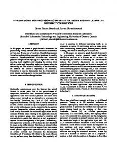
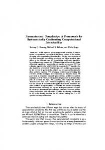
Like many methods, the requirements specification method CORE, comprises a number of development stages which deploy a number of different representation schemes. These stages are used to incrementally and iteratively produce a system requirements specification. In our ViewPoints terminology, CORE: the method may be described using a number of ViewPoint templates. Since each stage in CORE deploys a single, simple representation scheme, one way to describe CORE would be to describe each stage as a single ViewPoint template. Figs. 2 and 3 are sample, informal ViewPoint template descriptions of the agent structuring (AS) and the tabular collection (TC) stages of CORE, respectively. These stages support, respectively, problem decomposition in an agent hierarchy, and agent
A ViewPoint Template is a ViewPoint “type” in which only the style and work plan slots have been elaborated. A ViewPoint template, when instantiated, yields a ViewPoint - which can then be elaborated to produce a specification for a
-3-
STYLE
STYLE Object: Source
Object: Agent Attributes
Types
Name Identifier Icon
String Integer Bitmap
Values
Types
Icon
Bitmap
Types
Name Icon
String Bitmap
Values
Object: Input
Relation Part-of(Agent, Agent) Attributes
Attributes
Values
Attributes
Types
Name Icon
String Bitmap
Values
Object: Action
WORK PLAN Assembly Actions: add(Agent), remove(Agent), connect(Agent, Agent, Part-of), disconnect(Agent, Agent, Part-of) In-ViewPoint Check Actions: all-agents-connected, each-child-has-parent, no-name-clashes, ... Inter-ViewPoint Check Actions: For each agent in the agent hierarchy there must be one ViewPoint instantiated from a TC template, ... ViewPoint Trigger Actions: For each leaf agent create a new ViewPoint instantiated from a TC template, ...
Attributes
Types
Name Icon
String Bitmap
Values
Object: Output Attributes
Types
Name Icon
String Bitmap
Values
Object: Destination
Fig. 2: An informal description of CORE’s agent structuring (AS) ViewPoint template.
Attributes
Types
Name Icon
String Bitmap
Values
Relation Connected-to(Object, Object)
elaboration in a tabular collection form (see Figs. 5 and 6 in the next section for examples of ViewPoints instantiated from each template).
Attributes
Types
Icon
Bitmap
Values
WORK PLAN Assembly Actions: add(Source), remove(Source), add(Input), remove(Input), ..., connect(Source, Input, Connected-to), disconnect(Source, Input, Connected-to), ... In-ViewPoint Check Actions: all-sources -connected-to-inputs, all-inputs-connected-to-actions, no-actions-name-clashes, ... Inter-ViewPoint Check Actions: every Source or Destination in a tabular collection diagram has a corresponding agent with the same name in the agent hierarchy, the Output produced by one agent in a tabular collection diagram must be consumed as an Input in the tabular collection diagram another agent, ... ViewPoint Trigger Actions: Create a ViewPoint instantiated from an AS template if one does not already exist, ...
3.1. The Style Slot
For simplicity and convenience, the style slot of each template is described in terms of objects and relations, each having attributes with types and values (a BNF description may be more appropriate for text-based notations). We use a dot ( . ) to separate (from left to right) relations, objects, attributes and values. Thus, the term: Object1.Attribute1
identifies “the value of Attribute1 of Object1 ”. For example, if a “Process ” in a data flow diagram has a “Name ” attribute, then to identify the value of that attribute one would write: Process.Name
Similarly, the term: Relation1(Object1, Object2).Object1.Attribute1
Fig. 3: An informal description of CORE’s tabular collection (TC) ViewPoint template.
identifies “the value of Attribute1 of Object1 in the Relation1(Object1, Object2) ”.
-4-
A relationship itself may also have an attribute (e.g. the “label” of a transition arrow in a state transition diagram): Relation1(Object1, Object2).Attribute1 VP 1 VP 2
This identifies “the value of A t t r i b u t e 1 of Relation1 between Object1 and Object2”. Particular values in a specification (c . f . constants) may also be represented by concatenating them to the above expressions, and enclosing them in single quotes. For example, in state-transition diagram for a switch (which can be “On” or “Off”), the “On” state may be identified by:
VP 1 VP 2
State.Name.‘On’
while: Transition(On, Off).Name.‘Button-press’
identifies the Transition “Button-Press” between the and “Off” states.
“On”
VP 1 VP 2
3.2. The Work Plan Slot
In describing the work plan slot, we identify four generic categories of development actions. Assembly actions are those basic actions required to assemble (construct) a specification in the representation scheme defined in the style slot. They can be thought of as a collection of basic “editing” actions that one would expect a CASE tool supporting such a ViewPoint to provide. In-ViewPoint check actions are those actions required to check that a ViewPoint specification is locally (syntactically) consistent. Such syntactic checks partially define the semantics of a ViewPoint’s representation, and therefore define what a method designer decides is a “wellformed” specification in that representation. Inter-ViewPoint check actions, are those actions required to check the consistency between (overlapping or interacting) specifications residing in different ViewPoints. The relationships between such ViewPoints are described by inter-ViewPoint rules. We make no distinction between intratemplate rules (that describe relationships between ViewPoints instantiated from the same template) and inter-template rules (that describe relationships between ViewPoints instantiated from different templates). However, it is useful from a
VP 1 VP 2
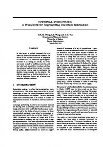
Two ViewPoints may be independent, non-overlapping and unrelated (except in that the method from which they are created requires both ViewPoints to exist). For example, a method may require the development of a ViewPoint describing the functional decomposition of a software system and another ViewPoint documenting the financial resources available to the project. Two ViewPoints may be nonoverlapping, but there is some existential relationship in which the existence of one depends in some way on the existence of the other. For example, the Z method requires that for each Z schema (ViewPoint), there is an associated textual description (ViewPoint). Two ViewPoints may be partially overlapping, with a partial specification in one related to a partial specification in the other. For example, CORE requires that a source agent in a tabular collection diagram is a named agent in the agent hierarchy. Two ViewPoints may be totally overlapping; that is, they describe the same domain in the same representation scheme. We may (1) require that any conflicts, discrepancies or inconsistencies be eventually resolved so that the two ViewPoints are made to say the same thing, or (2) accept that the two ViewPoints represent two different “views” of the same domain (e.g., different solutions to the same problem) that require evaluation and a choice to be made between them.
Fig. 4: Inter-ViewPoint relationships. Shaded areas represent overlaps between ViewPoints.
method engineering point of view to note the different relationships that may exist between ViewPoints in general (Fig. 4), since they may impact upon the way in which methods are used. For example, some ViewPoints use informal representations, and therefore the relationships they have with other ViewPoints are difficult to express concisely. Others are much more formal which makes expressing the relationships between them easier (providing these relationships exist and have been identified by a method designer). This is not to say that two ViewPoints which deploy formal representations are easier to relate.
-5-
Relating Z [55] and CSP [28] for example is nontrivial, as is relating natural language text with data flow diagrams. The key to expressing the relationships between multiple ViewPoints is therefore based on an understanding of the representation schemes deployed by both, and the identification of the areas of overlap or association. It is particularly challenging to describe inter-ViewPoint relationships in a generic manner, more so if the two ViewPoint specifications being related use representation styles with different underlying data models or schemas. Inter-ViewPoint check actions can, however, also use inter-ViewPoint rules to t r a n s f o r m information between ViewPoint specifications.
to describe such process models; e.g., empty-spec → [Assembly Actions] spec. spec → [Assembly Actions] spec. spec → [In-ViewPoint Check Actions] (consistent-in-VP-spec ∨ spec). consistent-in-VP-spec → [Inter-ViewPoint Check Actions] (consistent-inter-VP-spec ∨ spec). consistent-inter-VP-spec → [ ] end.
Clearly however, the above is a very simple process model that says “construct a partial specification by means of some assembly actions, and perform some checks from time to time, until inter-ViewPoint consistency is reached”. To provide “richer” process models, we have been exploring ways of “deriving” a ViewPoint specification state from the ViewPoint work record, and specifying finer-grain actions that may be performed if that ViewPoint is in one of the identified states. We have also constructed a prototype implementation that illustrates this, in which multiple (decentralised) process models interact to coordinate consistency checking between ViewPoint specifications [37]. Of course, each ViewPoint work plan may deploy its own particular process modelling or process programming [48] language to elaborate its individual specification development process (which greatly complicates ViewPoint interaction, and is not currently addressed in our work). Thus, a variety of process modelling languages may be used, such as the visual software process language proposed in [53] and many others [22]. The definition of multiple ViewPoints’ process models in this way also allows individual ViewPoint development processes to be modelled at different levels of granularity, to provide the appropriate level of method guidance for different developers [46]. Process integration [41] however, which in our setting means the integration of multiple process models to produce an overall, coherent development process, remains a problematic research area. One technique for such integration is proposed by Barghouti [5], which is based on a concurrency control mechanism developed for a co-operative software development environment. We believe that ViewPoint development process
While this paper concentrates on relationships that express “static semantics” (which, for example, apply to semi-formal representation schemes, functional specifications and contextsensitive aspects of well-formedness), the ViewPoints framework, in general, may also be used to organise and describe formal techniques and “dynamic semantics” (such as behaviour analysis for example). Finally, ViewPoint trigger actions must be performed in order to create new ViewPoints (i.e., instantiate ViewPoint templates) - very often “onthe-fly”. These actions are normally, but not always, performed as a consequence of one of the other development actions; e.g., adding an agent in an agent hierarchy should trigger the creation of a new ViewPoint for that agent, instantiated from the tabular collection template. A ViewPoint trigger action may also be regarded as a kind of inter-ViewPoint check action, since its scope is beyond that of the ViewPoint from which it is performed (see section 5 for an example). What the work plans in Figs. 2 and 3 do not show are the process models or process descriptions that may be used to guide ViewPoint owners in building ViewPoint specifications using the above actions. In particular, our approach, based as it is on the decentralisation of software development knowledge, requires local ViewPoint process models to coordinate and control development in this setting [16, 46]. A “precondition → [Action] postcondition” notation [11] may be used
-6-
models can be partly described by inconsistency handling rules, that specify how to act in the presence of inconsistency [21]. These rules can then be used to drive the development process both within and between individual ViewPoints, and are therefore vehicles for process integration. More generally, method engineering in the ViewPoints framework is discussed at length in [47].
DOMAIN Library World
STYLE Agent structuring notation definition
WORK PLAN Assembly Actions In-ViewPoint Check Actions Inter-ViewPoint Check Actions ViewPoint Trigger Actions + Process Model
4. Method Use: Requirements Specification
SPECIFICATION
v0 Library World
Once a requirements method has been designed and constructed, it may then be deployed to specify system requirements. Problem-specific (domain-specific) ViewPoints may be created by instantiating the appropriate ViewPoint templates, and their ViewPoint specifications developed by following individual ViewPoint work plans. The result of this development process is a configuration (structured collection) of ViewPoints which together form the total system requirements specification. At any point during development, different ViewPoint specifications may be overlapping and/or inconsistent with each other. Tolerating inconsistency [4] is fundamental to the ViewPoints approach, with consistency checking and conflict resolution not (necessarily) performed as a matter of course. Consistency checking may only be appropriate at specific stages of the development life-cycle and detection of inconsistency may not require immediate resolution, but left for later action, or even not resolved at all. This is in the nature of software development in general, and requirements engineering in particular, where contradictory requirements and alternative design solutions are commonplace. This approach to consistency management is echoed by Gabbay and Hunter [24] who argue for “making inconsistency respectable” and develop a logic-based framework in which “INCONSISTENCY implies ACTION”. In fact, as outlined in the last section, we have examined the applicability of such an inconsistency handling approach in the context of the ViewPoint framework [21] (see section 5.4 for a summary).
v1 Library
v2 Staff
v3 Borrowers
v21 Administrator
v4 Catalogue
v22 Librarian
WORK RECORD add(Library World), add(Library), add (staff), connect(Library World, Library, Part-of), add(Borrower), connect(Library, Staff, Part-of), connect(Library World, Borrower, Part-of), ...
Fig. 5: A sample ViewPoint instantiated from an agent structuring ViewPoint template. It describes the domain “Library World” in terms of an agent hierarchy. Example
The first graphical stage in CORE, agent structuring (AS), identifies the information processing entities (agents) in the problem domain, and arranges them in a hierarchy. The relation between child and parent in the hierarchy is that a child node is “part-of” a parent node. In specifying a computer-based library cataloguing system for example, the root of an agent hierarchy might be “Library World”. This is then decomposed into its constituent agents, which may then be decomposed further, and so on. Thus, we may develop a ViewPoint instantiated from the AS template for the domain “Library World”, with the specification shown in Fig. 5. The work record lists the “primitive” work plan actions that were performed to produce the current specification. These actions may be meaningfully annotated to provide a development rationale for the specification. One may however, wish to record “higher level” (specifier) actions, such as “decompose” and “backtrack”, which are
-7-
implemented in terms of more the more primitive (editing) operations. Souquières and Lévy [54] propose a framework for expressing both the incremental construction of a specification and the development rationale for the construction process. At this point during development, in-ViewPoint actions may be performed to check that the specification of the ViewPoint in Fig. 5 conforms to the syntactic rules imposed on its representation style. Inter-ViewPoint actions may also be performed, but no other ViewPoints have been created in this example yet. Performing ViewPoint trigger actions on the other hand causes the instantiation of the tabular collection (TC) template, one for each of the leaf agents in the agent hierarchy (as specified in the ViewPoint trigger actions part of the work plan of the AS template in Fig. 2). Thus, from the agent hierarchy in Fig. 5, five further ViewPoints (one for each leaf agent in the hierarchy) containing blank specifications (tables) are created. Each may then be developed separately by its ViewPoint owner who enacts the ViewPoint’s individual work plan. One such tabular collection ViewPoint (for the “Borrower” agent), in which some assembly actions have been performed, is shown in Fig. 6. It is again possible at this point to perform any of the ViewPoint’s work plan actions. One of the inter-ViewPoint actions for example, checks that every source and destination in the tabular collection specification is a named agent shown in the agent hierarchy in the AS ViewPoint. This check was specified textually in the interViewPoint check actions part of the work plan of the TC template in Fig. 3. If such a check fails, then some form of conflict resolution strategy must be employed in order for the check to succeed. Conflict resolution for this check in particular, implies that either a new agent must be added to the agent hierarchy specification in the AS ViewPoint, or the inconsistent source or destination must be renamed or removed from the specification of the TC ViewPoint. Approaches to conflict resolution (as distinguished from inconsistency handling) in the ViewPoints context have been examined, and models of conflict resolution proposed [15, 17]. A treatment of these
DOMAIN Borrower
STYLE Tabular collection notation definition
WORK PLAN Assembly Actions In-ViewPoint Check Actions Inter-ViewPoint Check Actions ViewPoint Trigger Actions + Process Model
SPECIFICATION SPECIFICATION Source
Library
Input
Action
publication
borrow
Output
publication
Destination
Library
return
WORK RECORD add(Library), add(Borrower), add(publication), connect(Library, publication, Connected-to), connect(publication, borrow, Connected-to), add(borrow), add(return), ...
Fig. 6: A sample ViewPoint instantiated from a tabular collection ViewPoint template. It partially describes the activities of “Borrower” in terms of a tabular collection diagram.
however, is beyond the scope of this paper. Although it is possible, in principle, to perform any of the generic work plan actions at anytime during specification development, each ViewPoint process model should prescribe when and under what circumstances it is appropriate to do so. For example, it would be unreasonable in most cases to perform inter-ViewPoint checks between two ViewPoints before the in-ViewPoint consistency of at least one of the two ViewPoints has been checked and established.
5. ViewPoint Integration Heterogeneity of notations, processes and specifications inevitably poses problems of integration. Within the ViewPoints framework, the relationships between ViewPoints need to be expressed, so that they may then be used to check consistency, and transfer and transform information between ViewPoint specifications. Thus, there is a need to define inter-ViewPoint rules that describe these relationships, specify
-8-
contain the rule. The broken lines in Fig. 8a illustrate the status of inter-ViewPoint rules at the definition stage of our model. Such rules relate hypothetical ViewPoints, VP S and VPD, with a hypothetical relationship, ℜ. That is, rules at this stage of the model refer to ViewPoint “types” (templates), rather than to actual “instances” (ViewPoints). In other words, they express what the method designer decides are the relationships between ViewPoints instantiated from particular ViewPoint templates. Thus, a method designer expressing the relationships between two ViewPoints is in fact stating that: if the ViewPoints VPS and VPD exist, then there should be a relationship ℜ that holds between them. The inclusion of such inter-ViewPoint rules in individual templates maintains the loose coupling and local management of each ViewPoint, which in turn facilitates the deployment of ViewPoints in a distributed environment.
when they may be invoked and how they should be applied. These activities straddle the processes of ViewPoint-oriented method construction and ViewPoint-oriented requirements specification. They are generic in that they do not prescribe how inter-ViewPoint rules are represented, or what mechanisms should be used for invoking and applying them. They are shown schematically in Fig. 7. Method Engineering
Inter-ViewPoint Rule DEFINITION
No
Method Use
Inter-ViewPoint Rule Destination INVOCATION ViewPoint
Inter-ViewPoint Rule APPLICATION success Inter-ViewPoint Relationship Holds
ViewPoint Trigger Action
New ViewPoint(s) fail
Step 1: Definition
VP
Step 2: Invocation
VP
Step 3: Application
VP
Rule Holds
VP
Inconsistency Handling (eg, Conflict Resolution)
Fig. 7: A model of ViewPoint integration activities. A labelled arrow indicates a precondition for the next step to be performed.
ℜ
VP
D
s
ℜ
s
VP
D
ℜ
VP
D
s
5.1. Step 1: Inter-ViewPoint Rule Definition
Inter-ViewPoint rules are defined in ViewPoint t e m p l a t e work plans and thus describe relationships between ViewPoints (instances) that have not yet been created. In other words, they describe relationships between ViewPoint templates or “types”. They are of the general form: ∀ VPS , ∃ VPD such that VPS ℜ VPD
s
ℜ
VP
D
Fig. 8: An interpretation of ViewPoint integration at various stages of the model. A broken line indicates that a ViewPoint or relation can exist or hold, but has not necessarily been established yet.
Now consider the existential quantifier in the general form of an inter-ViewPoint rule. Say for example we wish to write an inter-ViewPoint rule for the tabular collection stage of CORE which asserts that every source in a tabular collection diagram must be a named agent in the agent hierarchy. This rule makes a statement about every source in a tabular collection diagram, and can therefore be defined in the ViewPoint template describing tabular collection (TC). Furthermore, it requires information defined in the agent structuring (AS) ViewPoint template, and therefore
where VPS is the source ViewPoint in which the rule will reside, VPD is the destination ViewPoint (instantiated from a particular template) with which the relationship ℜ holds, and VPS ≠ VPD . VP S is universally quantified to indicate that the rule applies to every ViewPoint derived from the template in which the rule is defined. Once VPS has been instantiated from its template, this quantifier can be dropped, since all source ViewPoints instantiated from this template will
-9-
will require information outside the boundaries of the ViewPoint in which it is defined in order to get this information. Thus, what is required is a means of identifying the ViewPoint from which this information will be obtained; that is, a means of identifying VP D . Since there is no prior knowledge of what ViewPoints will be created during specification, one way to identify a ViewPoint is by specifying the template from which it will be instantiated, and perhaps the domain with which it will be concerned. Thus, a ViewPoint can be identified at rule definition time by a tuple: (t, d)
where t specifies the template from which the ViewPoint will be instantiated, and d specifies its domain (label) which is given by: d ∈ { Dp , Da , Ds , Dd } where, Dp denotes a particular (named) domain, Da denotes any domain not known at template construction time, Ds denotes the domain of the source ViewPoint, Dd denotes a different domain from the current (source) ViewPoint. Therefore, the general form of an inter-ViewPoint rule may be rewritten as: partial-spec-1 ℜ VP(t, d): partial-spec-2 where the p a r t i a l - s p e c - 1 describes a partial specification in the ViewPoint, VPS, created from the template in which the rule is defined, and which therefore does not require a ViewPoint identifier. The partial-spec-2 describes a partial specification in the ViewPoint (VPD) with domain d and instantiated from template t (denoted by the predicate VP(t, d)). A rule of the above form asserts that for every partial-spec-1 there should exist at least one partial-spec-2 with which the relationship ℜ holds. In this paper, partial-spec-1 and partial-spec2 actually denote individual partial specification components rather than partial specifications per se. Returning to the CORE rule we wish to define, it may be written in the TC ViewPoint template work plan as follows: Source.Name = VP(AS, Dd ): Agent.Name
This rule states that every N a m e attribute of Source objects in each VPS (instantiated from the TC template in which the rule resides), has an equal value Name attribute of Agent object in a VPD (instantiated from the AS template and relating to a domain, Dd , different from the source ViewPoint domain). A similar rule may be written to assert that every destination in a tabular collection diagram must be a named agent in the agent hierarchy: Destination.Name = VP(AS, Dd ): Agent.Name
Rules expressing the relationships between ViewPoints instantiated from the same template may also be written in the same way. Take the rule in CORE which asserts that every output from a tabular collection diagram must be an input in another tabular collection diagram for another agent (the destination agent for the original input). This rule (rule 1 in Fig. 9) may be written as: Connected-to(Output, Destination).Output.Name = VP(TC, Destination.Name): Connected-to(Ds, Input).Input.Name
where Destination.Name denotes the value of the particular (named) domain Dp. In many cases, a converse of each rule must also be included in the destination ViewPoint template, so that the rule may be invoked and applied by either ViewPoint. The converse of the above rule in this case also applies (rule 2 in Fig. 9). That is, every input from a source in a tabular collection diagram must have been produced as an output by the tabular collection diagram of that source agent: Connected-to(Source, Input).Input.Name = VP(TC, Source.Name): Connected-to(Output, Ds).Output.Name
where S o u r c e . N a m e denotes the value of the particular (named) domain Dp. Not every rule in CORE however has a valid converse; e.g., every agent in an agent hierarchy does NOT necessarily have to be a named source or destination in a tabular collection diagram. CORE however does require that the AS ViewPoint template contain a rule which asserts that every agent in an agent hierarchy must have a tabular
- 10 -
ViewPoint A (domain = "X") Source
Input
V
C
W
D
Action
E
Output
Destination
J
Y
Rule 1
Source
X
Input
Action
Output
Destination
J
K
J
L
N
P
M
Rule 2
ViewPoint B (domain = "Y") Fig. 9: An example of the relationships between two different tabular collection diagrams in two different ViewPoints, A and B. ViewPoint A contains rule 1, while ViewPoint B contains its converse, rule 2. Both rules are described in the text below.
collection diagram associated with it† . This may be written as: Agent → VP(TC, Agent.Name)
The above rule simply states that for every object there should be (→) a new ViewPoint instantiated from a tabular collection template, and concerned with the domain D p (whose value is given by Agent.Name). This is in fact a variation of the general form of inter-ViewPoint rules, in which the rule expresses some “existence” relationship, as opposed to the an “agreement” relationship. The above rules demonstrate the feasibility of expressing the relationships between multiple ViewPoints, once these relationships have been identified. The interested reader is referred to [16] for a more detailed account (and examples) of a variety of inter-ViewPoint rules for different methods, and in particular, the use of logical connectives to express, for example, patterns of the form “there may not exist”.
Agent
† In fact, CORE also has so-called “indirect” agents which only receive information, and which therefore do not have tabular collection diagrams associated with them. We ignore these for simplicity.
5.2. Step 2: Inter-ViewPoint Rule Invocation
Inter-ViewPoint rules are invoked by the owner of the ViewPoint in which they reside. At invocation time (Fig. 8b), an inter-ViewPoint rule asserts that for the ViewPoint VP S (which now exists because the rule was invoked from it), there should be at least one ViewPoint VPD , such that V P S ℜ VPD . If VPD does not exist, then a ViewPoint trigger action to create it must be performed before rule application (step 3) may be performed. The inter-ViewPoint rule invocation step is required for ensuring that the two ViewPoints, between which consistency needs to be checked or information transferred, are identified. A ViewPoint process model defines when interViewPoint rules should be invoked; e.g., “if condition X holds in VPS, then check that VPS ℜ VP D ”. In [46] we discuss three approaches to rule invocation: the “constrained”, in which rules are constantly invoked; the “pragmatic”, in which rule invocation may be turned on and off by the user; and the “process-oriented”, in which the process model guides rules invocation.
- 11 -
5.3. Step 3: Inter-ViewPoint Rule Application
The inter-ViewPoint rules defined in step 1 express the relationships between partial specifications residing in different ViewPoints. Inter-ViewPoint rule application is the process of checking the consistency between two ViewPoints whose consistency relationships are expressed by these rules. Consistency checking between two ViewPoints requires the interacting ViewPoints to engage in a communication protocol in which information in either or both ViewPoints is exchanged and compared. In a distributed setting, this includes the physical transfer of information from one ViewPoint to another, and typically, the transformation of this information into a form understood by the other ViewPoint. The mechanism for such interaction therefore also needs to be specified. The nature of any communication protocol however, depends on the requirements or goals of the interaction. Thus for example, a communication protocol between nodes in a wide area network, differs from that between cooperative, intelligent agents. Most inter-ViewPoint rules that traditional software engineering methods deploy, require some form of pattern matching to check that values of certain types of objects are related by simple binary relations (e.g., =, ). For example, it is frequently necessary to check that the string values of various named objects have been preserved or that integer values are within certain numerical limits. Other rules are more complex in that the relationships between the partial specifications are not simply a comparison between typed values. Instead the rules express a correspondence between different types of objects in different specifications. To avoid having to define all the rules from scratch during method definition, it should also be possible to define the relationships separately (in the form of a computer-based tool for example). Ideally, a method designer would be provided with a predefined library of relationships at his/her disposal, which can be adapted or customised. Of course, a method engineer, in designing a software
development method, should also choose many simple ViewPoint templates (that deploy simple representation schemes) thereby simplifying the relationships that need to be defined between these different templates. In our ViewPoint integration model, interViewPoint rule application takes method users through two general stages. On application of an inter-ViewPoint rule, the two ViewPoints VPS and VP D exist, but it is not yet known whether or not the relationship ℜ holds between them (Fig. 8c). Successful application of the rule, directly or after some conflict resolution (say), results in a valid relationship ℜ that holds between these two specific ViewPoints (Fig. 8d). The confirmation that a rule holds between two ViewPoints is an incremental step towards achieving greater ViewPoint integration. To pass through the above stages, ViewPoints need to exchange information. VP S needs to obtain a partial specification from VP D , and if necessary transform it into a form it can understand and manipulate (so that pattern matching, for example, can be performed). If the relationship ℜ fails to hold, then VPD needs to be made aware of this failure (i.e., another transfer), and some form of conflict resolution needs to be performed. In a typical software engineering setting, time constraints on such transfers may be insignificant, but if the ViewPoints are deployed in a real-time distributed environment (following a client-server model for example), then traditional problems such as communication load overhead or a high rate of change of fetched server information may become much more significant [52], and need to be considered in the design of an inter-ViewPoint communication protocol. We identify two modes of application of an inter-ViewPoint rule: Check Mode - in which question ?ℜ is asked; that is, does the relation ℜ hold between VPS and V P D . Consequently, either ℜ holds or inconsistency handling may be performed to make it, eventually, hold. Transfer Mode - in which the function ƒ(ℜ, VPS, V P D ) is applied to transfer and transform information between VP S and VPD , so that the relation ℜ will hold between them. The function
- 12 -
ƒ maps objects and relations in one ViewPoint to corresponding objects and relations in another. The key observation here is that ℜ expresses a one-to-one relationship between ViewPoints in which information is translated from one ViewPoint to another directly (without the need for an intermediary or global representation). An invoked inter-ViewPoint rule is normally applied in “check mode”. “Transfer mode” may be used initially or later on if the rule fails. Information transfers between ViewPoint specifications may therefore be used as vehicles for conflict resolution, although the effectiveness of the resolution will depend on the granularity of the transferred information and the nature of the conflict or inconsistency. We discuss the notions of conflicts and inconsistencies in more detail in [16], where we observe that an inconsistency is the result of the breaking of a rule, whereas a conflict denotes the interference of one party’s goals with the actions of another. Conflicts, of course, may manifest themselves as inconsistencies. Clearly, the infrastructure of ViewPoints needs to be extended to handle the various transfers and transformations that will occur during typical inter-ViewPoint communication. One such modification might be the addition of ViewPoint interfaces to provide information hiding and other transformation services. These interfaces may also provide “mailboxes” to which information from other ViewPoints may be “posted” rather than forcibly transferred into destination ViewPoint specifications. It is then left to the discretion of individual ViewPoint owners to incorporate information and/or guidance residing in their ViewPoint mailboxes into their local ViewPoint specifications.
loss of important information. Indeed, the “real world” (the domain of requirements engineers) forces us to work with inconsistencies, and we should therefore find ways to formalise some of the usually informal ways of responding to them. We do this, not by eradicating the inconsistencies, but by inconsistency handling, in which rules that specify how to act in the presence of inconsistency are explicitly specified. Our approach to inconsistency handling in this setting is discussed at length in [21]. Fig. 10 summarises our experimental inconsistency handling approach in which: • Partial specification knowledge in each ViewPoint is translated to first order classical logic; • Logical inconsistencies are identified; • Temporal logic (meta-level) rules are combined with the inconsistencies identified to specify inconsistency handling actions.
ViewPoint 1 Knowledge
?check consistency
ViewPoint 2 Knowledge
Translation Logical representation of ViewPoints and inter-ViewPoint specification information Identification of inconsistency
Inconsistent Data + Meta level inconsistency handling
5.4. Inconsistency Handling
It is worth reiterating our approach to consistency management in the ViewPoints framework, which is based on a philosophy of inconsistency management. We believe that maintaining consistency in multi-perspective software development is not always possible. In fact, we argue that at times it is not even desirable, since it can unnecessarily constrain the development process and lead to the
Action(s)
Fig. 10: Inconsistency handling in the ViewPoints framework. Selected knowledge in each of the interacting ViewPoints is translated into logical formulae and used to detect and identify inconsistencies. The meta-level rules can then be used to act upon these inconsistencies.
We are not of course claiming that classical logic is a universal formalism into which any two
- 13 -
representations may be translated. Rather, we argue that for any two partial specifications, a common representation may be found and used to detect and identify inconsistencies. 5.5. Structural Consequences
Inter-ViewPoint rule definition, invocation and application may be used to provide interesting structural information about methods, processes and specifications respectively, in the ViewPoints framework. From the ViewPoint templates and the interViewPoint rules defined within them (step 1), the structure of a method may be observed (Fig. 11). Template 1
problems of scaling-up the ViewPoints framework to cope with large numbers of ViewPoints. Kramer and Finkelstein [32] propose the use of structured configurations to cope with this inevitable complexity. We thus envisage the use of “configuration” or “management” ViewPoints to act as organisational “tools” for grouping together closely related ViewPoints [16]. ViewPoint 1
ViewPoint 4 ViewPoint 3 ViewPoint 5
Template 2
F i g . 1 3 : System specification (configuration) structure. Arrows denote inter-ViewPoint relationships that hold between the two connected ViewPoints. Broken arrows denote relationships that do not yet hold.
Template 4
Fig. 11: Method structure: a method is a configuration of ViewPoint templates, related by inter-ViewPoint rules. Connecting arrows denote inter-ViewPoint rules.
A snapshot of a project at step 2 on the other hand shows the ViewPoints that have already been created for a project so far, and indicates what ViewPoints may be created from this particular configuration of ViewPoints. The snapshot therefore provides a more method-specific structural view of the development p r o c e s s (Fig. 12). ViewPoint 1 ViewPoint 2
ViewPoint 3
ViewPoint 4
ViewPoint 5
Fig. 12: ViewPoint-oriented development process: at any point during a system’s development a number of ViewPoints will be under development, with further ViewPoints that need to be created from that point. Broken lines denote ViewPoints not yet created, but directly reachable from the source ViewPoint.
Finally, and by the end of step 3, a configuration of ViewPoints has been created and the relationships between them have been checked and established. The configuration of ViewPoints at this stage is therefore a structural view the system specification at a particular point in time (Fig. 13). Fig. 13 also illustrates the potential practical
ViewPoint 6
= System Specification
= Method Template 3
ViewPoint 2
6.
Experiences
To validate and demonstrate our approach, a number of case studies and computer-based tools were developed - an outline description of which follows. Related issues including conflict resolution [17], negotiation and dialogue [20], and configuration programming [32] were also examined in this setting. 6.1. Tool Support
A generic, computer-based prototype environment called The Viewer [45] has been built in Objectworks/Smalltalk, to support the ViewPoints framework. The Viewer (Fig. 14) runs on a variety of platforms (e.g., Apple Macintosh, PC/MS-Windows and Unix/X-Windows), and provides tools for method construction and deployment as outlined in sections 3 and 4 of the paper. A number of simple graphical diagramming techniques (such as hierarchical structuring and tabular data flow forms) have been described in ViewPoint templates and supported by CASE tools. These tools are partially generated from ViewPoint template descriptions using The Viewer’s meta-CASE capabilities. Development actions are automatically added to ViewPoint work records, and may be annotated individually to provide additional rationale or explanation of the
- 14 -
development actions. Some annotations (such as consistency checking results) are annotated to the work record automatically.
Fig. 14: The startup window of The Viewer. The “Method Designer” button invokes a “Template Browser” that supports the method engineering activities described in section 3. The “Method Use” button invokes tools for creating, developing and managing multiple ViewPoints.
The Viewer has also been extended in a variety of ways to explore ViewPoint interaction and integration as outlined in section 5. In particular, various protocols for inter-ViewPoint consistency checking and inconsistency handling have been implemented [35, 57], although the interViewPoint rules in all these cases were hard-coded into The Viewer. Our implementations of inter-ViewPoint consistency checking were based on our experiences in a number of related projects. Butcher [7] implemented a model of interViewPoint communication as dialogue in a Smalltalk-based tool called ICDC. We also constructed a simple toolset (called CoreDemo) to support part of the CORE method, and investigated several types of consistency checks and information transfers between CORE’s different stages [43]. Graubmann [26, 27] constructed a tightly integrated toolset to support ViewPoint templates describing a variant of Petri Nets [25]. ViewPoints developed by this toolset are managed by a hypertext-based environment called HyperView [26]. Continued work on a variety of communication models and their implementations is providing us with valuable experience in the expression and enactment of consistency checks and information transfers between many partial specifications. Thus for example, we were able to derive the general form of the rules described in section 5.1 by
reverse-engineering the hard-coded checks. We have designed, but have yet to implement, an extension of The Viewer, to fully support the model of ViewPoint integration described in this paper; and in particular, to use it as a vehicle for experimenting with a variety of inter-ViewPoint communication protocols. However, both academic and industrial experiences of using The Viewer have been encouraging, and at the very least have demonstrated “proof-of-concept” of our ViewPoints-based approach. 6.2. Case Studies
We have also used the organisational and structuring principles of the ViewPoints framework in a number of case studies of various sizes. In [35] the entire CORE method was described using ViewPoint templates and T h e Viewer. In [57], the Constructive Design Approach (CDA) [33] to the development of distributed systems was also developed, and supported by an extension of The Viewer. Our CDA case study was particularly illuminating, because we already had a special-purpose tool [34] which supported the CDA method and which maintained consistency between views at all times. Our approach of tolerating inconsistency in using The Viewer to support the CDA proved to be comparably effective. In a collaborative case study with HewlettPackard Research Labs (UK) [3], we tested the feasibility of both our approach and HP’s newly developed object-oriented method, FUSION [10]. The case study provided us with feedback about the ViewPoints framework, and HP with feedback about the documentation and structuring capabilities of their method. Siemens (Munich, Germany) have also used the ViewPoints framework to develop their own Petri Nets-based method, and have developed a special purpose Petri Nets editor and simulator based on the framework (the HyperView tool mentioned in section 6.1). Finally, we developed a method called VSCS [8] (adapted from the Object Modelling Technique (OMT) [51]) with an objective of producing formal specifications in Modal Action Logic [11]. The method was used to partly specify
- 15 -
an automatic teller machine, and further demonstrated the feasibility of our approach.
8.
Related Work
Work in a number of software engineering fields has made its mark on our ViewPoints framework. Analogies of ViewPoints may be found in multidatabases [6], including work on interoperable, heterogeneous, multidatabase systems [1, 38]. Multidatabases deploy many, heterogeneous - possibly distributed - databases, based on more than one data model or schema. Many of the problems of checking consistency between such databases are therefore identical to the problems of checking and integrating multiple ViewPoint representation styles and specifications developed in those styles. Research in the areas of method and tool integration and integrated project support environments also tackles many of the issues surrounding integration in the ViewPoints setting (e.g., [9, 30, 39, 59]). These issues include process modelling and integrated CASE tool support. Only a few integration models however, rely on the controlled transfer of information between a number of databases [56] in which objects are related via inter-database relationships [13]. Furthermore, system specification from multiple perspectives has been investigated in various guises by a number of authors. Doerry et al. [14] propose a model for composite system design based on multiple cooperating/interacting agents with individual behaviours and goals. Dardenne et al. [12] describe a goal-directed approach to composite system development, while Feather [19] suggests using many, parallel “evolutionary transformations”, which may then be merged by replaying them sequentially. Work on program transformation [60, 61] provides an additional vehicle for tackling consistency checks and information transfers between different ViewPoints. Robinson [49] proposes a multiple perspectives integration architecture as part of a model of specification design. Meyers and Reiss [40] study interperspective (cf. inter-ViewPoint) communication, and propose the development of a single canonical representation for software specification. Finally,
Niskier et al. [44] propose a pluralistic knowledge-based approach to software specification in the style we favour - using multiple overlapping views elaborated using multiple representation schemes. However, their implementation of this, PRISMA, tightly couples the fixed views and uses a common, centralised (bottle-necked) data structure to express consistency checks.
9.
Conclusions and Further Work
ViewPoints facilitate the partitioning of a problem domain into loosely-coupled, distributable objects that encapsulate partial specifications described in different notations and locally developed and managed according to different work plans. Although representation, development and specification knowledge are all bundled into the same object to facilitate local management and distribution, they are separated within a single ViewPoint into slots to facilitate their individual manipulation and enhance their tailorability and reusability. Tolerating the coexistence of multiple, heterogeneous ViewPoints to specify system requirements brings to the fore the problems of integration - these include the integration of specification fragments described using different notations, and the integration of methods and tools used to develop such descriptions. In this paper we have explored the use of interViewPoint rules to express the relationships between different ViewPoints. These rules are defined during method construction, and invoked and applied during specification development. They frequently define the “regions of overlap” between pairs of ViewPoints, and thus identify “redundant” (but perhaps desirable) information. Moreover, while these rules describe syntactic relations between partial specifications in different ViewPoints, we may also view these same rules as definitions of semantic relations between these partial specifications. Further work is still needed however to describe more domain-specific knowledge and rules (e.g., conceptual and ontological relationships [58]). One avenue of investigation may be to develop the role of ViewPoint owners in providing this domain
- 16 -
knowledge. In general, inter-ViewPoint rules themselves play a number of important roles in ViewPointoriented requirements engineering. First, they describe the relationships between different development techniques that form methods. In this context they are a vehicle for method integration. Second, they describe the relationships between the different tools that support the constituent development techniques that form methods. In this context they are a vehicle for tool integration. Third, they describe the relationships between various specification fragments found in different ViewPoint specifications. In this context they may be used to check consistency between partial specifications, or to transfer and transform information in one ViewPoint specification to another. Finally, ViewPoints may also be used to represent development participants, and therefore inter-ViewPoint rules describe protocols of interaction and behaviour between such participants. In this context, they provide an infrastructure for computer-supported cooperative work (CSCW). In this paper we have concentrated on the problem of expressing these inter-ViewPoint rules for the purposes of inter-ViewPoint consistency checking. We have tried to describe these rules, independent of the mechanisms or communication protocols that will be deployed to invoke and apply them. In fact we have also said very little about the notation for describing the actual relations, ℜ, between ViewPoints. These need to be explored further by looking at more complex relations than those demonstrated by our examples (namely, “agreement” (=) and “entailment” (→), which we nevertheless believe are typical of many software engineering methods). We further believe that these rules may have an alternative mode of application to consistency checking, namely, a transfer mode. This is analogous to Prolog rules, for example, which may succeed, fail or generate the solutions that satisfy a rule. The mechanisms for using these modes of application in the ViewPoints setting are currently being investigated. We believe that the transfer mode of inter-ViewPoint rule application deals with the issue of language translation in our framework,
where more work is needed. Finally, while we have not yet tested our framework in any large industrial setting, the feedback from the case studies we have performed and The Viewer prototype have been very encouraging. Purely from an organisational point of view, the ViewPoints framework has proved useful in understanding the way in which methods are constructed and used. ViewPoints have also served as vehicles for reducing the complexity of software development of heterogeneous, composite systems, by the simple application of the separation of concerns principle. Thus, while a number of software engineering problems remain to be explored, we believe our framework has, at the very least, clarified our research agenda. In particular, it has allowed us to envisage the consequences of “radical” decentralisation of software engineering knowledge. The use of many simple, distributed, pairwise rules between ViewPoints whose invocation and application is coordinated by ViewPoint process models, while not conventional, has proved to be useful and practicable. Acknowledgements We would like to gratefully acknowledge the extensive constructive comments of Axel van Lamsweerde on an earlier version of this paper. Thanks are also due to Steve Easterbrook and the anonymous reviewers for their feedback, and to Michael Goedicke for his contributions to the ViewPoints framework. This work was partly funded by the UK Department of Trade and Industry (DTI) as part of the ESF project. An earlier version of this paper appeared in the Proceedings of the 15th International Conference on Software Engineering (IEEE CS Press).
References [1]
[2]
[3]
- 17 -
R. Ahmed, P. De Smedt, W. Du, W. Kent, M. Ketabchi, W. Litwin, A. Rafii and M. Shan (1991); “The Pegasus Heterogeneous Multidatabase System”; Computer, 24(12): 19-27, December 1991; IEEE Computer Society Press. M. Ainsworth, A. H. Cruickshank, L. G. Groves and P. J. L. Wallis (1994); “Viewpoint Specification and Z”; Information and Software Technology, 36(1): February 1994; Butterworth-Heinemann. L. A. R. Ballesteros (1992); “Using ViewPoints to Support the FUSION Object-Oriented Method”; M.Sc. Thesis, September 1992; Department of Computing, Imperial College, London, UK.
[4]
[5]
[6]
[7]
[8]
[9]
[10]
[11]
[12]
[13]
[14]
R. Balzer (1991); “Tolerating Inconsistency”; Proceedings of 13th International Conference on Software Engineering (ICSE-13), Austin, Texas, USA, 13-17th May 1991, 158-165; IEEE Computer Society Press. N. Barghouti (1992); “Supporting Cooperation in the MARVEL Process-Centered Environment (Proceedings of ACM SIGSOFT Symposium on Software Development Environments)”; Software Engineering Notes, 17(5): 21-31, December 1992; SIGSOFT & ACM Press. M. W. Bright, A. R. Hurson and S. H. Pakzad (1992); “A Taxonomy and Current Issues in Multidatabase Systems”; Computer, 25(3): 50-60, March 1992; IEEE Computer Society Press. W. Butcher (1988); “ICDC - An Implementation of Dialogue in Smalltalk-80”; M.Sc. thesis, September 1988; Department of Computing, Imperial College, London, UK. J. Castro and A. Finkelstein (1991); “VSCS: An Object Oriented Method for Requirements Elicitation and Formalisation”; FOREST project report, NFR/WP2.2/IC/R/002/A; October 1991; Department of Computing, Imperial College, London, UK. G. Clemm and L. Osterweil (1990); “A Mechanism for Environment Integration”; Transactions on Programming Languages and Systems, 12(1): 1-25, January 1990; ACM Press. D. Coleman, P. Arnold, S. Bodoff, C. Dollin, H. Gilchrist, F. Hayes and P. Jeremaes (1993); ObjectOriented Development: The Fusion Method; Prentice-Hall, Engelwood Cliffs, NJ, USA. R. Cunningham, A. Finkelstein, S. Goldsack, T. Maibaum and C. Potts (1985); “Formal Requirements Specification - The FOREST Project”; Proceedings of 3rd International Workshop on Software Specification and Design (IWSSD-3), IEEE Computer Society Press. A. Dardenne, S. Fickas and A. van Lamsweerde (1993); “Goal-directed Requirements Acquisition”; Science of Computer Programming, 20: 3-50, 1993; K. R. Dittrich (1989); “The DAMOLKLES Database System for Design Applications: Its Past, its Present, and its Future”; (In) Software Engineering Environments: Research and Practice; K. H. Bennett (Ed.); 151-171; Ellis Horwood Ltd., Chichester, UK. E. Doerry, S. Fickas, R. Helm and M. Feather (1991); “A Model for Composite System Design”; Proceedings of 6th International Workshop on Software Specification and Design (IWSSD-6), Como, Italy, 25-26 October 1991, 216-219; IEEE Computer Society Press.
[15] S. Easterbrook (1993); “Domain Modelling with Hierarchies of Alternative Viewpoints”; Proceedings of International Symposium on Requirements Engineering (RE ‘93), San Diego, CA, USA, 4-6th January 1993, 65-72; IEEE Computer Society Press. [16] S. Easterbrook, A. Finkelstein, J. Kramer and B. Nuseibeh (1994); “Coordinating Distributed ViewPoints: The Anatomy of a Consistency Check”; (to appear in) Concurrent Engineering: Research and Applications, August 1994; CERA Institute, West Bloomfield, USA. [17] S. M. Easterbrook (1991); “Elicitation of Requirements from Multiple Perspectives”; Ph.D. Thesis, June 1991; Department of Computing, Imperial College, London, UK. [18] M. S. Feather (1987); “Language Support for the Specification and Development of Composite Systems”; Transactions on Programming Languages and Systems, 9(2): 198-234, April 1987; ACM Press. [19] M. S. Feather (1989); “Constructing Specifications by Combining Parallel Elaborations”; Transactions on Software Engineering, 15(2): 198-208, February 1989; IEEE Computer Society Press. [20] A. Finkelstein and H. Fuks (1989); “Multi-party Specification”; Proceedings of 5th International Workshop on Software Specification and Design (IWSSD-5), Pittsburgh, Pennsylvania, USA, 1920th May 1989, 185-195; IEEE Computer Society Press. [21] A. Finkelstein, D. Gabbay, A. Hunter, J. Kramer and B. Nuseibeh (1994); “Inconsistency Handling in Multi-Perspective Specifications”; (to appear in) Transactions on Software Engineering, IEEE Computer Society Press (an earlier version of this paper appeared in the Proceedings of 4th European Software Engineering Conference - ESEC ‘93, September 1993, LNCS 717, Springer-Verlag). [22] A. Finkelstein, J. Kramer and B. Nuseibeh (Eds.) (1994); Software Process Modelling and Technology, Advanced Software Development Series, Research Studies Press Ltd. (Wiley), Somerset, UK. [23] A. Finkelstein, J. Kramer, B. Nuseibeh, L. Finkelstein and M. Goedicke (1992); “Viewpoints: A Framework for Integrating Multiple Perspectives in System Development”; International Journal of Software Engineering and Knowledge Engineering, 2(1): 31-58, March 1992; World Scientific Publishing Co. [24] D. Gabbay and A. Hunter (1991); “Making Inconsistency Respectable: A Logical Framework for Inconsistency in Reasoning, Part 1 - A Position Paper”; Proceedings of the Fundamentals of Artificial Intelligence Research ‘91, 19-32; LNCS, 535, Springer-Verlag.
- 18 -
[25] P. Graubmann (1990); “Definition of SPEC Nets”; REX technical report, REX-WP3-SIE-008-V1.0; July 1990; Siemens, Germany. [26] P. Graubmann (1992); “The HyperView Tool Standard Methods”; REX technical report, REXWP3-SIE-021-V1.0; January 1992; Siemens, Germany. [27] P. Graubmann (1992); “The Petri Net Method ViewPoints in the HyperView Tool”; REX technical report, REX-WP3-SIE-023-V1.0; January 1992; Siemens, Germany. [28] C. A. R. Hoare (1985); Communicating Sequential Processes; Prentice-Hall International, Engelwood Cliffs, New Jersey, USA. [29] M. Jackson (1990); “Some Complexities in Computer-Based Systems and Their Implications for System Development”; Proceedings of International Conference on Computer Systems and Software Engineering (CompEuro ‘90), Tel-Aviv, Israel, 810th May 1990, 344-351; IEEE Computer Society Press. [30] M. Jarke (1992); “Strategies for Integrating CASE Environments”; Software, 35(3): 54-61, March 1992; IEEE Computer Society Press. [31] G. Kotonya and I. Sommerville (1992); “Viewpoints for Requirements Definition”; Software Engineering Journal, 7(6): 375-387, November 1992; IEE on behalf of the BCS and the IEE. [32] J. Kramer (1991); “A Configurable Framework for Method and Tool Integration”; Proceedings of European Symposium on Software development Environments and CASE Technology, Königswinter, Germany, June 1991, 233-257; LNCS, 509, Springer-Verlag. [33] J. Kramer, J. Magee and A. Finkelstein (1990); “A Constructive Approach to the Design of Distributed Systems”; Proceeding of 10th International Conference on Distributed Computing Systems, Paris, France, 28th May-1st June, 580-587; IEEE Computer Society Press. [34] J. Kramer, J. Magee, K. Ng and M. Sloman (1993); “The System Architect’s Assistant for Design and Construction of Distributed Systems”; Proceedings of 4th Workshop on Future Trends of Distributed Computing Systems, Lisbon, Portugal, September 1993, 284-290; IEEE Computer Society Press. [35] F. K. Lai (1993); “CORE in The Viewer”; M.Sc. Thesis, September 1993; Department of Computing, Imperial College, London, UK. [36] J. C. S. P. Leite and P. A. Freeman (1991); “Requirements Validation Through Viewpoint Resolution”; Transactions on Software Engineering, 12(12): 1253-1269, December 1991; IEEE Computer Society Press.
[37] U. Leonhardt (1994); “Process Modelling in The Viewer”; M.Eng. thesis, June 1994; Department of Computing, Imperial College, London, UK. [38] W. Litwin, L. Mark and N. Roussopoulos (1990); “Interoperability of Multiple Autonomous Databases”; ACM Computing Surveys, 22(3): 267293, September 1990; ACM Press. [39] S. Meyers (1991); “Difficulties in Integrating Multiview Development Systems”; Software, 8(7): 49-57, January 1991; IEEE Computer Society Press. [40] S. Meyers and S. P. Reiss (1991); “A System for Multiparadigm Development of Software Systems”; Proceedings of 6th International Workshop on Software Specification and Design (IWSSD-6), Como, Italy, 25-26th October 1991, 202-209; IEEE Computer Society Press. [41] P. Mi and W. Scacchi (1992); “Process Integration in CASE Environments”; Software, 35(3): 45-53, March 1992; IEEE Computer Society Press. [42] G. Mullery (1979); “CORE - a method for controlled requirements expression”; Proceedings of 4th International Conference on Software Engineering (ICSE-4), 126-135; IEEE Computer Society Press. [43] G. Mullery (1985); “Acquisition - Environment”; (In) Distributed Systems: Methods and Tools for Specification; M. Paul and H. Siegert (Eds.); LNCS, 190, Springer-Verlag, [44] C. Niskier, T. Maibaum and D. Schwabe (1989); “A Pluralistic Knowledge-Based Approach to Software Specification”; Proceedings of 2nd European Software Engineering Conference (ESEC ‘89), University of Warwick, Coventry, UK, 11-15th September 1989, 411-423; LNCS, 387, SpringerVerlag. [45] B. Nuseibeh and A. Finkelstein (1992); “ViewPoints: A Vehicle for Method and Tool Integration”; Proceedings of 5th International Workshop on Computer-Aided Software Engineering (CASE ‘92), Montreal, Canada, 6-10th July 1992, 50-60; IEEE Computer Society Press. [46] B. Nuseibeh, A. Finkelstein and J. Kramer (1993); “Fine-Grain Process Modelling”; Proceedings of 7th International Workshop on Software Specification and Design (IWSSD-7), Redondo Beach, California, USA, 6-7 December 1993, 42-46; IEEE Computer Society Press. [47] B. Nuseibeh, A. Finkelstein and J. Kramer (1994); “Method Engineering for Multi-Perspective Software Development”; (to appear in) Information and Software Technology, Butterworth Heinemann. [48] L. Osterweil (1987); “Software Processes Are Software Too”; Proceedings of 9th International Conference on Software Engineering (ICSE-9), Monterey, California, USA, 3rd March - 2nd April 1987, 2-13; IEEE Computer Society Press.
- 19 -
[49] W. Robinson (1989); “Integrating Multiple Specifications Using Domain Goals”; Proceedings of 5th International Workshop on Software Specification and Design (IWSSD-5), Pittsburgh, Pennsylvania, USA, 19-20th May 1989, 219-226; IEEE Computer Society Press. [50] D. T. Ross (1977); “Structured Analysis (SA): A Language for Communicating Ideas”; Transactions on Software Engineering, 3(1): 16-34, January 1977; IEEE Computer Society Press. [51] J. Rumbaugh, M. Blaha, W. Premerlani, F. Eddy and W. Lorensen (1991); Object-Oriented Modelling and Design; Prentice-Hall, Inc., Engelwood Cliffs, New Jersey, USA. [52] M. Satyanarayanan (1991); “An Agenda for Research in Large-Scale Distributed Data Repositories”; Proceedings of International Workshop on Operating Systems of the 90s and Beyond, Germany, July 1991, 2-12; LNCS, 563, Springer-Verlag. [53] T. Shepard, S. Sibbald and C. Wortley (1992); “A Visual Software Process Language”; Communications of the ACM, 35(4): 37-44, April 1992; ACM Press. [54] J. Souquières and N. Lévy (1993); “Description of Specification Developments”; Proceedings of International Symposium on Requirements Engineering (RE ‘93), San Diego, CA, USA, 4-6th January 1993, 216-223; IEEE Computer Society Press. [55] J. M. Spivey (1989); The Z Notation: A Reference Manual; Prentice-Hall International, UK. [56] M. Stanley (1990); “Typing in an Object Management System (OMS)”; Proceedings of International Workshop on Environments, Chinon, France, September 1989, 235-250; LNCS, 467, Springer-Verlag. [57] T. Thanitsukkarn (1993); “The Constructive Viewer”; M.Sc. Thesis, September 1993; Department of Computing, Imperial College, London, UK. [58] Y. Wand and R. Weber (1990); “An Ontological Model of an Information System”; Transactions on Software Engineering, 16(11): 1282-1292, November 1990; IEEE Computer Society Press. [59] A. I. Wasserman (1990); “Tool Integration in Software Engineering Environments”; Proceedings of International Workshop on Environments, Chinon, France, September 1989, 137-149; LNCS, 467, Springer-Verlag.
[60] D. S. Wile (1986); “Local Formalisms: Widening the Spectrum of Wide-Spectrum Languages”; (In) Program Specification and Transformation (Proceedings of IFIP TC2/WG2.1 Working Conference on Program Specification and Transformation, Bed Tölz, 15-17th April 1986); L. G. L. T. Meertens (Ed.); 459-482; Elsevier Science B.V., Holland. [61] D. S. Wile (1992); “Integrating Syntaxes and their Associated Semantics”; Technical report, RR-92297; 1992; USC/Information Sciences Institute, University of Southern California, Marina del Rey, California, USA. [62] P. Zave (1989); “A Compositional Approach to Multiparadigm Programming”; Software, 5(5): 1525, September 1989; IEEE Computer Society Press. [63] P. Zave and M. Jackson (1993); “Conjunction as Composition”; Transactions on Software Engineering and Methodology, 2(4): 379-411, October 1993; ACM Press.
- 20 -