A Framework for Run-time Systems and its Visual Programming Language Alan M. Durham Universidade de Sso Paulo
[email protected] Ralph E. Johnson University of Illinois
[email protected]
Abstract
1
Frameworks and domain-specific visual languages are two different reuse techniques, the first targeted at expert programmers, the second at domain experts. In fact, these techniques are closely related. This paper shows how to develop a domain-specific visual language by first developing a white-box framework for the domain, then turning it into a black-box framework, and finally building a graphical front end for it. We used this technique in a compiler to specify run-time systems. Research: reuse, components, and frameworks
Domain-specific software tools can be very productive. For example, GUI builders can generate most of the code for a user interface. They are usually based on a well defined model of interaction between the graphical interface and the applicaA GUI designer uses a tion software. domain-specific visual language to specify which of a series of pre-defined components are used and how they interact Somewith the underlying application.
Permission to make digital/hard copy of part or all of this work for Person& or classroom use is granted without fee provided that copies are not made or distributed for profit or commercial advantage, Fe qopyright noti@% the title of the publication and its date appear, and notice 1sgiven that copying is by permission of ACM, Inc. To copy other$e, to,!epubli$ !o post on servers, or to redistribute to lists, requires pnor SpeClflC PermIssIon and/or a fee. OOPSLA ‘96 CA, USA Q 1996 Af3vl 0-89791-788~W96/OOt0...$3.50
406
Introduction
times only the choice and location of components are specified visually, other times the interaction is also specified visually, but the specification language is always specialized for user interfaces. It is a lot easier to design a good visual language when domain-specific there is already a graphical notation used Some notations, like in that domain. that of GUls, come right out of the problem domain. Others, like PERT charts,
have been developed by clomain experts and just have to be automated. But often there is no existing language. What should a tool designer do then? This paper presents a way of developing a visual language as part of framework design. We used this technique to develop a visual language for implementing the run-time system of a compiler. Compilers are a popular domain for developing software tools. Compilers have a well-known standard architecture, with parts such as lexical analysis, parsing, static analysis, and machine code generation. Some parts of a compiler are often automated, such as parsers [Knu65] code gen[La1651 [Joh75] and machine eration [Mi170] [Gla77] [Cat%] [HC86] [PLG88] [Fra89] [ESL89]. Other parts, such as static analysis (type checking and code optimization), have structured approaches that make them easier to implement (such as attribute grammars [Mad801 [B.H78] [FS89]), but are not yet completely automated. We found that the standard architecture did not make it easy to change the implementation of a language’s run-time system, and there were no tools for specifying the run-time system of a language, even though this has been noted as an important problem [She881 [Gab851 [Kra83]. So, we built a visual language-based tool for specifying run-time systems that works alongside the older parser-generators and codegenerator-generators. Our work is part of the ‘I’S project [.JGZ88], an optimizing compiler for typed Smalltalk, written in Smalltalk-80. Our
407
goal was to develop a tool that could be used to specify not only Smalltalk’s runtime system, but the run-time systems for other languages as well. Such a tool would let us experiment with run-time system design. Due to the lack of previous work in the field, we had to create a new model for run-time systems that could be used to develop high-level tools for run-time system specification. We wanted to automate as much of the task as possible, and to enable compiler writers to specify run-time systems by writing as little code as possible. This paper describes how such a system was developed, and the lessons we learned in the process. Our system was developed in three phases. First we centralized all information about run-time systems in a single class. This class could be subclassed to produce new run-time systems, providing some degree of code reuse. The class had three components that could be replaced, but there were lots of dependencies between them. A this point, the run-time system module was a whitebox framework[JF88] Next, we refined the three components so they could be built by composing them from even smaller components. Some classes had to be subclassed but there seemed to be an upper bound to the number of classes that were needed. Eventually, it was possible to specify a run-time system entirely by composing existing classes. At this point, the run-time system module was a black-box framework. Finally, we created a visual
class the node classes that generated code for the features being changed, while the RTLBuilder would have to change if the environment implementation changed. The classes that needed changing would not depend on the structure of the runtime system but on which parts of the ab2 Phase 1: Creating a stract syntax tree and of the RTLBuilder were in charge of generating the correwhite-box framework sponding code. The only way to underInitially, the TS compiler consisted of a stand the run-time system being implefront-end and a back-end. The front-end mented was to read the code generation would produce an abstract syntax tree, routines that were distributed over the abcheck and optimize it, and then convert stract syntax tree node class hierarchy. it into an intermediate form in a register To centralize all information about the transfer language called RTL. There was run-time system, we created a new class, a class hierarchy of abstract syntax tree RunTimeSystemsExpert, that would hold nodes (the Interpreter pattern[GHJV95]). all the knowledge about the run-time sysEach node class had methods for optimizatem. The front end classes did not commution and for generating the intermediate nicate directly with the back-end anymore, code. The back-end, called RTLBuilder, but would ask the RunTimeSystemsExconstructed the RTL program (using the pert to generate code for a run-time sysBuilder pattern[GHJV95]) and then optitem function. Each abstract syntax node mized it and generated code for it. would basically ask the RunTimeSystemRun-time system information was di- Expert to generate code for it. This is an vided between the front-end and the backexample of the Visitor pattern[GHJV95]. end. The front-end knew how to impleRunTimeSystemsExpert then issued the ment operations on primitive data types proper code generation requests to the and how objects were laid out in memory, RTLBuilder. The RTLBuilder no longer but the back-end was responsible for regis- knew anything about how to implement RTLBuilder was reter allocation, parameter passing, and ac- the environment. cessing local variables. The RTLBuilcler duced to generating code for expressions, interface for generating RTL code was low- memory and variable access, assignment, level, and exposed many details of the in- conditional jumps, calls and returns. Initially, RunTimeSystemsExpert was a termediate RTL code. large object with little internal structure. Unfortunately, this meant that changes It kept track of things like the registers asto the run-time system woulcl require changing both the front-end and the back- signecl to temporary variables and labels of branches. Although it delegated the task end. The front-end would have to sublanguage for specifying the run-time system, along with browsers to inspect implementations. We think the same approach could be used to develop systems for other problem domains.
408
of building register transfers to the RTLBuilder, it did everything else itself. This new structure encapsulated new run-time systems, but did not reduce the total amount of new code that had to be Each new run-time system rewritten. quired a new subclass of RunTimeSystemsExpert, no matter how tiny the differences would be. A small modification of an existing run-time system could be implemented easily by redefining the methods corresponding to the changed functions. However, there were interdependenties among the various methods. For example, access and update methods both shared knowledge about some specific forIt was clear that Runmat feature. TimeSystemsExpert needed to be decomposed further. We started trying to determine the functions implemented by all run-time systems, trying to obtain a more modular and reusable system, and also to obtain an initial class hierarchy for run-time systems. The first step was to group the various methods of the RunTimeSystemsExpert. Three groups arose: l
the methods
related
to primitive
data
types, 0 the methods related implementation, l
the methods
related
to environment
to control
flow.
The primitive data types group was the biggest. It had an operation for each operation on each data type, so there would be operations like “generate code for adding
409
two integers” and “generate code for fetching an element from an array”. Except for integers, no data type seemed common to all run-time systems, so even inheritance did not seem useful. It also seemed to be the most difficult to automate, because primitive data types can be arbitrarily complex. The environment group seemed to be more clearly defined. Most languages have the same type of information in environments. Environments must access and update arguments, temporaries, and other variables. We also made environments responsible for manipulating predefined locations in memory, such as entry points into the operating system and addresses of the memory management routines. The control flow group included methconditional ods for generating calls, jumps, case, return and message send. We then divided the RunTimeSystemsExpert into three components, one for each group of methods, and made a This parclass for each component. titioned the run-time system implementation work into independent sub-tasks. However, there were still dependencies between components. The message send operation needed to know the structure of objects, classes, and method dictionaries, which were all primitive data types, but it also needed to use control flow operations and is a kind of high-level control Procedure calls involve flow operation. creating new context frames, a task associated with the environment group of messages. Also, literals in Smalltalk are associated with both the envirotiment and the
primitive data types, because the environment knows where they are stored, but the primitive data type knows how they are represented. The result was that the RunTimeSysternExpert would not only communicate with its components, but they would communicate with each other. Most communication was unidirectional, from the RunTimeSystemExpert to the components, but it was important for each component to have an interface that the other components would use. Ideally, each component would have a fixed interface, so it would be easy to replace one version of a component with another. If the interfaces could stay the same, one component could be changed independently of other components. This is an example of the OpenClosed Principle. [Mey88] The problem is how to achieve this principle.
3
Phase 2: Creating black-box framework
a
Once we had defined the components of RunTimeSystemExpert, we tried to make them more general. We wanted to be able to implement any run-time system, so the new components should have an interface general enough to be used by any run- time system. The final goal was to be able to provide a descriptive specification that the components would use to produce code. The compiler writer should not have to subclass the components or have to decipher the code generatiou routines.
410
3.1
Control
flow
Making the control flow component more general involved determining which control flow operations were common to all run-time systems and which ones were specific to certain groups of run-time systems. The basic Pascal-type control flow commands seemed to be generic, but fancy operations like message send were specific to a group of run-time systems. One possibility was to have a superclass with an interface for all basic control flow operations, and a subclass for each group of “fancy” control flow operations. However, it slowly became clear to us that all “fancy” control flow in high level languages had two important characteristics: they were implemented in terms of the more basic ones, and they were always associated with a primitive data type. In other words, fancy control flow operations were in fact basic operations on primitive data types. This changed our approach to control flow. The control flow component just implemented All other operathe basic operations. tions were implemented in the the primitive data
types module*
primitive data types 3 2 * Initially, we had a specific message for each type of request of the Smalltalk front-end. Messages to access the class of an object, message to get a specific instance variable, messages to allocate objects, messages to get a specific constant. However, the goal was to make a new run-time system require as little Smalltalk code as possible.
The solution was to create a table of primitive data type definitions, ancl to make a data type definition be an object that knew how to generate code for each of its operations. Thus, the unbounded set of primitive data types operations was reduced to a small number of operations like “fetch data type from table” and “generate code for operation on data type”. The specification of the code for the operation could be stored in a table, indexed by the operations’ names. It was still hard to create a data type definition, but the individual definitions were now reusable between run-time systems, and the interface to the data types was now simple. All primitive operations were expressed as a low level RTL program. The RunTimeSystemsExpert could pass the primitive description to the RTLBuilder, which would splice in the code at compile-time. Now, instead of having to create a new subclass for each new set of primitive data types, one would only have to write, in RTL, the appropriate set of primitive operations, giving each one a name. The interface of the Primitive Data Types component was reduced to only a few messages: 0 messages to generate code for a specific primitive operation of a given data type. to generate the run-time 0 messages representation of a constant for a given data type
However, it also became clear that, for a given run-time system, the semantics of basic operations was essentially the same across various implementations, while the format of the data types could vary a lot. The best example of this is probably inIntegers can be represented ditegers. rectly in their machine representation, can have low-bit tags or can have high-bit tags. All “small” integers’ have the same operations, only the data representation differs. We decided to separate the description of data type format and the description of the semantics of the basic operations. This way changes in data type formats could be more easily implemented, increasing the modularity of the system. Both format and semantics could be expressed using RTL code. Using code to specify semantics seemed reasonable to us, but we wanted to have a more descriptive specification for formats. A program needs to know the format of a data type to access and update its various fields. These fields were grouped together in data blocks or inside a reference word that could be in memory or in We decided to create a class registers2. to describe each kind of field. Our ultimate goal was to find all possible types of fields, references, and data blocks. Once ’ 5mall” be
and
messages for testing the data a given object reference.
type of
therefore 2A
store that
411
represented be
are in
generally a single
operated
by
integers machine
that word,
a single
machine
inside
reference
instruction words
l
integers
can
good are
example Lisp’s
both cout.ains
the
of
cells.
CAR
and
the reference.
fields Some the
implementations CDR
in the
word
this goal was accomplished, formats could be described by just selecting which types of fields were necessary, without writing any code. The PDTField hierarchy was designed to keep all necessary information regarding fields of data types. We constructed a hierarchy of 10 classes to represent fields. This hierarchy includes classes for standard data fields, absolute pointers, relative pointers, indirect pointers, and multiple (indexed) fields. Pointer field descriptors have enough information to distinguish between pointers to other objects and pointers to data blocks. All code is generated automatically by the classes’ methods using the information stored in the instance variables. One additional advantage of having specific classes to describe the format of data types is that we can write methods to extract information about formats, such as routines to support garbage collection. The PDTField hierarchy was designed to be static. New subclasses should be added only if some unpredicted type of field is desired, which should not occur often. Compiler writers should not need to do this subclassing. We also developed a small class hierarchy to describe data blocks and object references. This hierarchy included the classes DataBlock, PDTRefe,rerace and a common abstract class, class Field~Iokkr. This hierarchy was also static.
412
3.3
Environment
Environments look a lot like data types. There are a standard set of operations applied on them (like the primitive operations of data types). They have a fixed set of entries (much like the fields of data types). We considered joining the environment component to the primitive data types component at first, but decided against it. There were two main reasons behind it. First, we found that the operations on environments did not change at all, so there was no need to require the user to write RTL code for them. Second, runtime systems specified much more carefully the placement of environment entries than placement of data type fields. Fields of data types are just part of a data block or of the reference. The allocation and placement of this data block is not specified with the data type. Environment descriptions, on the other hand, have to specify if entries go in the stack, in the heap, or even in registers. Some entries may even go at pre-defined addresses. Also, there is no notion of “typing” of entries in the same sense as in data types. The semantics of most of the information that is placed in the environment is not of the environment’s concern, the environment’s task is only to keep this information, not to process it. The only information that. is processed by the environment components is the information about how to do static and dynamic linking. In other words, information on how t,o manipulate context fra.mes. Therefore, the environ tnent specification was a separate,
customized component. Environment has four classes of entries:
a allocating 0 creating
context
frames.
a new temporary.
0 arguments l
0 implicit
arguments
0 temporaries a global variables
and constants
Arguments are the standard arguments, present in most message and procedure calls. Implicit arguments are the arguments added by the compiler like, for example, the receiver of a message. Temporaries are the environment entries that depend on the source code, like temporaries for computing expressions, environment locations for dumping registers, etc. Global variables and constants are the environment entries that are not part0 of an activation record. These entries can go anywhere in memory. The first three types of entries are the ones that go into context frames. Context frames are allocated and deallocated during the execution of a program, and the environment component should know how to generate code for this allocation and deallocation. Arguments and implicit arguments are allocated by the caller and temporaries can be allocated by the caller or by the callee. Global variables can have their values retrieved and updated, but there is no need to allocate space for them at run-time. The interface for the environment component is also fixed. There are methods to generate code for: l
accessing and updating argument,s, implicit arguments and lemporaries.
413
accessing ables.
and
updating
global
vari-
Environment entries can be placed almost anywhere. The position of an environment entry is described by the class RTLLocution. Each instance of this class is able to generate code for accessing and updating that location. A compiler writer can describe the environment by selecting the appropriate locations. No code will need to be written. There is a specific subclass of the RTLLocation hierarchy to describe each type of location: register location, frame location, data type location. A data type location specifies a data type and a field, and it generates code by delegating to the primitive data types component. This lets the front-end be completely independent of the format of the primitive data types, though it depends on the names of the data types and the names of the operations they support.
4
Phase 3: Creating a visual interface
Having created a black- box framework for specifying the run-time systetn, the next step was creating a visud language ancl associated tools. These tools would then generate the components of the compiler. The information that is best specified graphically is the format of primitive clata types. Both locations and fields can specified by a series of semi-graphical windows.
Since the set of classes is fixed, the user just specifies which type of location or field and then fills in information specific to that kind of location or field. We also created browsers to specify environments and data types. Each browser has a specific format to conform to the characteristics of the underlying component. 4.1
Specifying Data Types
the
Primitive
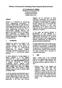
Each instance of the PrimitiveDataTypesBrowser holds the descriptions of all the data types of a single run-time system. An example of such a browser can be seen in fig. 2. The browser is quite similar to the system browser of Smalltalk-80. We have four sub-windows plus a radio button. The four windows are: l
data type window (topmost,
l
operation most)
l
code window
l
data type most)
window
(topmost,
leftmost) right-
(center)
format
window
(bottom-
Selecting a data type in the data type window will cause a graphi& description of its format to be drawn in the data type format window, and a list of operations to appear in the operations window. The selection of the radio button will determine which operations will appear: primitive operations (“MAIN” button), auxiliary operations (used internally by the
414
primitive operations’ code, “AUX” button), and constant generation (“CONST” button). When an operation is selected its RTL code will appear in the code window, In our figure we have selected the primitive data type bogus and selected the primitive operation demoOperation. The format window shows that this data type is represented by a data block of 3 fields, the first called class, the second size and the third instance variable. Any reference to such data type will have a pointer to this data block (as represented by the line linking the “REFERENCE” box to the “DATA BLOCK” box. The third box is a description of the instVElrfield, which is an indexed field (i.e. ‘PDTVariantRepetitionField’) whose total size is in field size. All entries of instVar are 32 bits long, the first one being at displacement 2[0] (that is, second 32-bit word, bit 0). The code window is a standard text editor that can be used to specify RTL code for the basic operations of the primitive data types. The RTL code can refer to fields by their name and the system will automatically generate code for access or update (whichever is the case). In the figure the second instance of multiple field instlhr receives the content of field class. The data format window is used to clisplay the data type’s format and also to specify it. We specify a new format for a datatype selecting the option “acid field” of the pop up menu. You are then guided by a series of request to specify the type of field, its clata block aud the appropriate information to describe the field. All the specification is done by selecting options of
menus and by filling up entries 4.2
Specifying
in boxes.
the environment
The EnvironmentBrowser is simpler than the PrimitiveDataTypesBrowser. Figure 1 shows that it has only two sub-windows and a set of radio buttons. The radio buttons are used to select a group of environment entries: global variables, arguments, tempararies, and implicit arguments. Seletting a radio button causes the defined environment entries of the corresponding group to appear in the top window. Selecting an entry causes the browser to display a textual description of the location associated to it.
entry is similar to describing a field. The pop up menu of the topmost window has a “new entry” option. The user has the choice of just writing the textual description directly or engaging in a dialog that is entirely menu and form-driven.
5
I: Environment
Browser
Figure 1 SLOWS the implicit argument met/iod selected for inspection. The textual description states that the implicit argument nlethorl is located at displacenient 0 (7,ero) of the main context frame and that it will conta.in a reference to a da.ta type. Describing a new environment
415
the
Control
We did not create a tool to specify the flow of control because there are few alternatives. Most languages share the same set of basic control flow operations, which is implemented by class ControlFlow, whose methods generate each of the control flow operations. Usually a “new form of control flow” is associated with a specific data type, such as a continuation or an object, so it can be specified as an operation on that primitive data type using the PrimitiveDataTypeBrowser. Implementing that basic control flow operations differently requires making a new subclass of ControlFlow, but we do not expect this to be necessary.
6 Figure
Specifying Flow
6.1
A method for creating visual languages ~~~
specification
tools
differ
Any tool that can be used to specify a system incorporates a model for generating We can divide these tools in the system. two groups: tools that provide a closed model of the resulting system, and tools
that only provide the user with a syntactic model to transform high-level specifications into low-level implementations. Tools in the first group hide from the user all the details of the final form of the system, and tools in the second group provide a language that expresses this final form. One example of tools in the first group are GUI builders [Ale871 [PS94]. The user has no idea of how the interfaces they specify are going to be implemented. They are provided with a model of interaction between the figures and applications. A set of interface types is given to the user, together with a composition model. We can use a visual language to perform this composition. The only code the user needs to write is the code to perform communication with the application, and even this is limited. An example of the second set of tools are attribute grammar systems [B.H78] [Mad80]. The user specifies the system using a specialized programming language. A syntactic substitution transforms the specification into the realization of the system. This substitution is guicled by the syntactic rules given by the user. The tool itself has little semantics associated with it. The tool hides many of the details of the transformation, but the user must still know how the target system functions. At a first glance it would seem a mistake to choose the second type of tools over the first, but the first type of tool is not always possible. We can only provide a black-box view of the final system implementation when all the possible options are known. That difference became very clear dur-
416
ing the development of our system. Semantics of primitive data types can be arbitrarily complex and we had no hope of inventing a model that woulcl permit the development of a tool of the first kind. Therefore we chose to perform the syntactic translation. The user is presented with a translation model: primitive operations names into RTL code, where RTL is the implementation model. For each operation, the user specifies the RTL implementation for it. However, we were able to better delimit the problem in the other cases. We created a fixed class hierarchy of field descriptors that could describe the format and functionality of any of the data type fields we have investigated. The same happened with locations for environment entries. We also successfully separated the environments into 4 different types of locations, according to the way they are manipulated at run-time. We created a fixed universe of options, and also a model to compose these fixed options. This let us construct a high-level language to specify those parts of the system. The user does not need to understand the final implementation for this part of the system. 6.2
An approach to developing a domain specific visual programming language
The first step in developing a domain specific visual programming language is to clearly delimit the domain. This task is not as trivial as it may seem. A good approach is to start with a specific exam-
ple in the problem domain. This is what was clone in the first phase of our project. Our problem domain wa.8 run-time system implementation, our example was the TS compiler. The lack of previous research in the specific problem of specifying a whole run-time system made the task less obvious, and increased the importance of working initially with a specific example. Once the problem is delimited for the specific chosen example, we should try to break it into independent subproblems. It is important in this phase to compare the specific problem you are solving with other problems in the domain. This will help in finding a set of useful subdomains. The result is probably a white-box framework. After a set of subdomains is found the next step is to produce independent components to solve each of the subproblems found. The subproblems should be as independent from each other as possible. Any dependencies should be expressable through a fixed interface. The result is a black- box framework. Since the goal is to provide a domainspecific visual language, we need to find the basic units of this language. For each component of the system, determine the variability. If there are a fixed set of possibilities for a component, create a set of classes to describe them. Instances of these classes should be able to produce a solution for the specific subproblem they tackle, given t,he state information they hold. When we cannot find such a fixed a language should be set of possibilities, chosen to specify how to map the requests to the component into a solution. In our
417
case we chose RTL for specifying the semantics of the primitive operations. The next step is to give the final form to the visual language. Each subcomponent of the system can have its own visual tool. This tool will provide the users with ways of specifying the solutions of each of the subproblems of the problem domain. Components with fixed set of possible classes can use a menu and dialog box type of language. The final step is to develop a tool for organizing existing solutions and for specifying new ones. This tool is usually some kind of browser. The browser should offer an organized list of solutions and some visualization for them. This visualization is often graphical, but sometimes a textual description is more clear.
7
Conclusion
This paper describes a general-purpose technique for designing a domain-specific visual programming language. We’ve seen it used in other frameworks, but none of them have been publically documented, and the technique itself has not been described before. It should be a key tool for framework designers.
References [Ale871
PainJames II. Alexander. less panes for Smalltalk windows. In Pmceedings of OOPSL.4 ‘$7, Object-Oriented Progwnl~rning Sjystems, Lnnguqes
and Applications, pages 287294, November 1987. printed as SIGPLAN Notices, 23(11). [B .~78]
[Cat781
[ESL89]
[Fra89]
[FS89]
B.H.Mayoh. Attribute Grammurs and mathematical semantics. PhD thesis, Computer Science Department, Aarhus University, Aarhus Denmark, 1978. R. G. G. Catell. Formafization and Automatic Derivation of Cocle Generators. PhD thesis, Computer Science Departmen t , Carnegie-Mellon University, 1978. Hemu t Emmelmann, FredrichWilhelm Schroer, and Rudolf Landwehr. A generator for efficient back ends. In Proceedings of the ACM SIGPLAN Conference on Programming Languages and Design and Implementation, pages 227-237, 1989.
ings of the ACM SIGPLAN Conference on Programming Languages and Design and Impfementation, pages 120-130, 1989. [Gab851
R. Gabriel. Performance and Evaluation of LISP Systems. MIT Press, 1985.
[GH JV95]
Erich Gamma, Richard Helm, Ralph Johnson, and John VlisDesign Patterns: Elsides. ements of Reusable Software. Addison Wesley, 1995.
[Gla77]
Robert Steven Glanville. A Machine Independent Algorithm for Code Generation and Its Use in Retnrgeatable Compilers. PhD thesis, Computer Science Department, University of California at Berkeley, 1977.
[HC86]
Philip J. Hatcher and Thomas W. Christopher. High Quality Code Generation Via Bottom-Up Tree Pattern Matching. In Proceedings of the 13th Symposium on Principles of Progranmnzing Lnngtlclges, pages 119-130, January 1986.
[dF88]
Ralph JohnE. son and Brian Foote. Designing reusable classes. .Journnl of Object-O.riented Progmtnnzing, l(2):%35, 1988.
Christopher W. Fraser. A language for writing code generators. In Proceedings of the ACM SIGPLAN Conference on Programming Lnnguages and Design and Impkmentntion, pages 238-245, 1989. Rodney Farrow and Alec G. Stanculescu. A VHDL compiler based on attribute grammar met hodolonv. In Proceed-
418
[JGZBB]
Ralph E. Johnson, Justin 0. Graver, and Lawrence W. ZuTS: An optimizing raws ki . compiler for Smalltalk. In Proceeding5 of OOPSLA ‘$8, Object-Oriented Programming Systems, Languages and Applications, pages 18-26, November 1988. printed as SIGPLAN Notices, 23( 11).
[Joh75]
S.C. Johnson. YACC: Yet Another Compiler Compiler. Technical Report Technical Report 32, Bell Laboratories, 1975.
[Knu65]
D. E. Knuth. On the translation of languages from left to right. Information nnd Control, (8):607-639, 196.5.
[Kra83]
Glenn Krasner. Smalltallc-50, bits of history, words of advice. Addison Wesley, 1983.
[La1651
W. R. Lalonde. An efficient lalr parser generator. Infornacltion und Control, (8):607-639, 196.5.
[Mad801
Ole Lehrmann Madsen. On defining semantics by means of extended attribute gramIn Senanntics-directed mars. C’ompiler GenerationLecture Notes In Computer Science 94, pages 259-299. Springer Verlag, 1980.
419
[MeyBB]
Bertrand Meyer. ObjectOriented Software Construction. Prentice-Hall, 1988.
W701
Perry L. Miller. Automatic code generation from an object-machine Technical Redescription. port Technical Memorandum 18, Project MAC - MIT, 1970.
[PLGBB]
and Ed uardo Pellegri-Llopard Susan L. Graham. Optimal Code Generation for ExpresAn Aplication sion Trees: In Proof BURS Theory. ceedings of the 15th Symposium on Principles of Programming Languages, pages 309318, January 1988.
[PS94]
Inc ParcPlace Systems. Visualworks User’s Guide, 1994.
[She881
Stanley T. Shebbs. Implementing Primitive Datatypes for Higher-level Languuges. PhD thesis, Department of Computer Science of the University of Utah, 1988.
NAME: InstVar PosItion: 2101 Size: 32 BitMask: A[34 DataBlock: header Type of Repeated Field: PDTPointerField Total Size In Field: size
Figure 2: Primit,ive
420
Data Types
Browser