the use of a transaction processing monitor. The ... (Client Server Software Performance Engineering) ..... network types, transactions, remote procedure calls.
Proc. 1997 CMG Conference, Dec. 1997, Orlando, FL.
A FRAMEWORK FOR SOFTWARE PERFORMANCE ENGINEERING OF CLIENT/SERVER SYSTEMS Daniel A. Menascé Department of Computer Science, MS 4A5 George Mason University 4400 University Blvd, Fairfax, VA 22030-4444 http://www.cs.gmu.edu/faculty/menasce.html Designers of new client/server (C/S) applications have many choices such as use of three-tiered architectures, work distribution between clients and servers, distribution of functions and DB tables among servers, and others. This paper presents a languagebased framework for Software Performance Engineering in C/S environments. The language allows for the specification of objects such as clients, servers, DB tables, networks, and transactions. A specification of a C/S system in this language compiles into an analytic model used to predict the performance of the new system.
1. Introduction An increasing number of organizations are moving several mission-critical applications from mainframe environments to client/server systems. Application designers are faced with a large number of software architectural choices that may severely impact the performance and cost of the resulting system. Examples of these options include the distribution of work between client and server, use of three tiered C/S architectures, distribution of functions among servers, distribution of database tables among servers, type of client and servers, and network connectivity. Waiting until the application is ready to go into production is not a viable option since poor performance may require major code redesign and rewrite. This is usually very expensive in terms of development cost and cost incurred by a delayed deployment of the new application. To ensure that the new application will meet the performance requirements, software performance engineering [Grummitt91, Smith90, Menascé94, Wilson91] techniques have to be employed during the software design and development process. These techniques estimate the demands of the new application and use analytic performance models to predict the performance of the new system. This paper presents a framework for software performance engineering (SPE) studies for client/server systems. The techniques and approaches discussed here were developed during the course of an actual SPE study carried out by the Proc. 1997 CMG Conference, Dec. 1997, Orlando, FL.
author for a major downsizing effort. The C/S system involves a three-tier C/S architecture, LANs and WANS, application and database servers, as well as the use of a transaction processing monitor. The 1 approach is based on a language called Clisspe (Client Server Software Performance Engineering) developed by the author. The language allows for the specification of objects such as clients, servers, database tables, networks, and transactions. A Clisspe specification compiles into an analytic queuing network model for the C/S system allowing for the capacity planning of the application under development. There are several commercial tools such as SPE.ED, QASE, SES/workbench and others that can be used for software performance engineering. Some of these tools are based on simulation while some use simulation and analytic models. Most provide a graphical interface for specifying hardware and software systems. We decided to develop our own set of tools for the study at hand since i) we would have more control over the underlying models used; for example, the Clisspe system models DBMS query optimizers at a considerable level of detail, ii) it would not require us to go through the learning curve associated with the adoption of new tools, and iii) we wanted the software designers to use the Clisspe language to specify their use cases. This way, Clisspe could be used by both software system designers and performance engineers. One of the major deterrents for the widespread use of SPE is that SPE is viewed 1
The Clisspe tool is not a commercial system. It was developed by the author for the use in a major SPE study.
Proc. 1997 CMG Conference, Dec. 1997, Orlando, FL. by many as an activity separate from software design and development, and therefore should be carried out by people with different skills. With our languageoriented approach, we strove to bridge the gap between these two camps. In fact, in the project that prompted this study, all Clisspe programs were written by a system designer who is not an expert in performance. Section two describes the motivating example used throughout the paper. Section three discusses basic issues in SPE for C/S systems. Section four describes a methodology for SPE in C/S systems. Section five describes the Clisspe language and section six discusses the Clisspe system. Section seven presents some performance results for the motivating example. Finally, section eight presents some concluding remarks.
Client/Server RTS recruitment center
recruitment center
LAN
LAN
applic. DB server server
DB applic. server server
WAN
Headquarters LAN application servers
DB servers
Figure 1 - Client/Server Configuration for RTS.
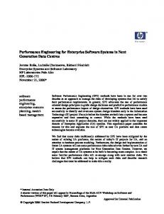
2. Motivating Example The application that prompted the study and methodology reported in this paper is a Recruitment and Training System (RTS) that is being downsized from a mainframe-based system to a client/server environment. Applicants go to recruitment centers spread all over the country. There, a guiding counselor interviews the applicant and tries to match the applicant skills with the agency’s desired skills. Accepted applicants are recruited and are assigned to one or more training classes where they will acquire the skills needed for the job. The current application and databases reside on an aging mainframe that is expensive to maintain. The current application has a line-oriented user interface and is difficult to maintain since many programs are over 20 years old and the application is written in many different programming languages. Also, due to its centralized nature, the current system does not scale well with the number of users. The new environment, shown in Fig. 1, is composed of several recruitment centers where several client workstations are interconnected through a 10Mbps Ethernet LAN. Each recruitment center may or may not have a local application server and a local database server. Recruitment centers are connected through a Wide Area Network (WAN) to the headquarters LAN where one or more application and database servers are located. Figure 2 shows a simplified version of the EntityRelationship (E-R) diagram for the RTS application. The entities are Applicant, Skill, Course, and Section (of a course). The E-R diagram was mapped into a relational DB schema composed of the nine DB tables illustrated in Fig. 3.
© 1997 D. A. Menascé. All Rights Reserved.
. . .
has
Applicant
needs
. .
Skill
. .
requires
develops
. Course .
enrolls
. Section .
taught
Figure 2 - Entity-Relationship Diagram for the RTS application. The developers needed to answer several questions such as: • How ‘’thin’’ should the client software be? • How much work should be done at the client versus at the application server? • How should the DB be distributed? ◊ how many DB servers do we need? ◊ which tables should be stored in each DB server? ◊ should tables be partitioned by rows and stored at different DB servers? ◊ should tables be replicated and how? • What kind of hardware and OS platform should be used for the application servers? • What kind of hardware and OS platform should be used for the DB servers? • What kind of storage box should be used to support the DB server? • How many DB and application servers are needed and where should they be located?
2
Proc. 1997 CMG Conference, Dec. 1997, Orlando, FL. • What type of networking technology and connectivity should be used? • What DBMS should be used to support the DB server? • What indexes should be created on the various DB tables? The above questions are general questions that arise scenarios, namely: • Will the new application requirements? • How many clients will be cost? Applicant SSN Name StreetAddress City
instances of the more in SPE studies for C/S meet the service level
the development phase. Performance is not taken into account until the system is ready to go into production. At this time, performance is assessed (see Fig. 4). If system performance is not satisfactory, the problem has to be fixed. Unfortunately, fixing the problem at such a late stage in the development may be too costly since major software rewrites and architectural changes may be required. functional & performance reqs.
Requirement Analysis
System Design
supported and at what
Program Design
fix it
Zip Phone Education ...
Program Coding
Skill SkillCode SkillName SkillDescription SkillMinVal SkillMaxVal Course CourseNum CourseName NumHours Description
NO
YES
Section CourseNum SectionNum StartDate DayTime Location MaxCap Enrollment CourseNum SectionNum SSN
CourseDevelopsSkill CourseNum SkillCode
ApplicantHasSkill SSN SkillCode SkillValue
CourseRequiresSkill CourseNum SkillCode
ApplicantNeedsSkill SSN SkillCode SkillValue
Figure 3 - DB Schema for RTS Application. To answer these questions one needs to build a performance model for the C/S system under development and estimate its input parameters. Since we will be using queuing network models, we need to obtain the following types of parameters: • Workload Intensity Parameters: identify the load in terms of number of transactions per unit time. Examples include: ◊ number of SQL requests/sec, and ◊ number of transactions of each type/sec. • Service Demand Parameters: identify the total time spent by a transaction at each system component. Some examples are: ◊ average CPU time per transaction at the DB server, at the application server, at the client, ◊ average I/O time per transaction at the DB and at the application server, and ◊ average LAN and WAN time per transaction. 3. Basic Issues in SPE In most software development projects, only the functional requirements are taken into account during © 1997 D. A. Menascé. All Rights Reserved.
System Testing
is performance OK?
Figure 4 - Common Software Development Approach. The preferred approach is to integrate performance prediction and assessment into all phases of the software development life cycle as illustrated in Fig. 5. Requirement Analysis
feedback path System Design Program Design
performance requirements estimated service demands
Performance Model
Program Coding measured service demands
System Testing
Figure 5 - Integration of software development with performance modeling. The Requirements Analysis phase generates performance requirements. The system design, program design, and program coding phases generate estimates of the service demands that can be used as input parameters in SPE studies that in turn generate feedback to the designers as design and development proceeds. At the testing stage, actual service demands can be used for final performance assessment and performance tuning. The goal is that by integrating performance in all stages of the software 3
Proc. 1997 CMG Conference, Dec. 1997, Orlando, FL. development life cycle, one can guarantee that the resulting system will exhibit the desired performance. Each phase of the software development life cycle generates different kinds of inputs to SPE studies as illustrated by Fig. 6, which was adapted from a similar figure presented by the author in [Menascé94]. This adapted version includes some parameters germane to C/S environments. • service levels (response times, throughputs, etc) • hardware/software base (client and software platforms, networking technologies, DBMSs)
Requirement Analysis
• mapping of software modules to C/S architecture • database design • networking topology
System Design
• number of I/Os and DBMS calls per transaction • estimates of CPU demand • estimates of network traffic
Program Design
• refined I/O and CPU demand estimates • refined network traffic demand estimates
Program Coding
• measured I/O, CPU, and network service demand estimates
System Testing
Figure 6 - Input Parameters to SPE from Software Development Lifecycle. 4. A Methodology for SPE in C/S Systems The main steps to be followed in SPE studies for C/S environments are: • Understand the Environment: ◊ determine the critical transactions using the 80/20 rule: 20% of transactions that are likely to use 80% of the resources. ◊ determine the cost and technology constraints (e.g., what client and server hardware/software platforms should be used, what networking technologies are to be used) ◊ determine the service levels for the critical transactions. ◊ determine the base C/S architecture. ◊ is there a mainframe version of the application? • Characterize the Workload: for each critical transaction, find: ◊ estimated workload intensity (if there is a mainframe based system, get these from there). ◊ estimated service demands for: client and server processors, client and server disks, LAN segments, WANs, and routers. • Build a Performance Model: build a performance model (typically a queuing network model) that corresponds to the complete system. • Solve the Performance Model: ◊ obtain response times and throughputs per transaction
◊ obtain a break down of the response time per device ◊ determine bottlenecks. • Performance Assessment: ◊ compare estimated performance metrics with service levels. ◊ if performance is poor, verify where transactions spend most of their time and give feedback to system designers to cause changes in: ∗ software architecture ∗ work distribution between clients and servers ∗ database allocation to servers ∗ allocation of servers to network.
Obtaining service demand estimates for all system components may be a daunting task if not supported by a tool that automates the process. For this reason, we decided to develop an automated approach to derive the service demands at clients, servers, and networks from a specification of the various transactions and objects in a C/S system under the development. This approach is based on a language we developed called Clisspe (Client Server Software Performance Engineering). The language allows developers of new applications to assess the performance of the application under development. Through the language, users can declare objects involved in the new system (e.g, clients, servers, networks, database tables, and transactions) as well as specify the flow of execution of the transactions under development. A compiler for Clisspe generates the input parameters for queuing network models used for performance prediction. Next section describes in more detail the Clisspe system. 2
5. The Clisspe Language The Clisspe language allows designers of C/S systems to describe different kinds of objects such as servers, clients, databases, database tables, transactions, and networks, as well as the relationship between them. Examples of relationships include mappings of servers and clients to networks and mappings of database tables to servers. The language also allows the designer to specify the actions executed by each transaction. Clisspe has three sections: a declaration section, a mapping section, and a transaction specification section. The declaration section is used to declare the following objects: clients and client types, servers and server types, disks and disk types, database management systems, database tables, networks and network types, transactions, remote procedure calls (RPCs), and numeric constants. 2
© 1997 D. A. Menascé. All Rights Reserved.
Pronounced clisspee. 4
Proc. 1997 CMG Conference, Dec. 1997, Orlando, FL. The mapping section is used to: allocate clients to networks, allocate servers to networks, assign transactions to clients, specify network paths (from clients to servers going through several networks), and assign database tables to servers. Finally, the transaction specification section is used to specify the logic of each of the major transactions. This specification is oriented towards software performance engineering. Therefore, loop specifications indicate the average number of times a loop is executed, branch statements indicate the probability that a certain path is followed, and case statements indicate the probability each option is executed. We now present examples of the declaration, mapping, and transaction sections of the Clisspe language for the RTS application. These examples were overly simplified due to the paper’s space limitation and because the purpose of the paper is to present the approach and discuss its benefits and not to be a thorough description of the language. All characters in a line after a “!” sign are considered comments. Figure 7 shows the declaration section for the RTS example. Lines 3 and 4 of the declaration section declare constants used later on in the Clisspe program. Line 5 declares the DBMS to be used as well as DBMS’s page size. The Clisspe compiler models the query optimizer for various DBMSs and derives the I/O and CPU service demands for DB select and update statements. Line 6 declares a client type used in the declaration of client groups (see line 8). The declaration of a client type includes its SPEC (Standard Performance Evaluation Corporation) ratings: SPECint92 and SPECfp92 (see [SPEC]). This declaration also declares a parameter, IO_benchmark, used to declare the parameters (a and b) of a function f (x) = a x + b where x is the number of bytes read/written and f(x) is the CPU time in milliseconds to read or write x bytes. The parameters a and b must be computed through linear regression on a set of (x, f(x)) points obtained through measurements on a client with a SPECint92 given by the parameter specint92 after the a and b values. The Clisspe compiler scales up or down the measurements as needed to match the SPECint92 rating of the client type. Lines 8 and 9 declare a group of 100 clients of type Pentium120. Line 10 declares a disk type along with its performance characteristics (seek, average latency, and transfer rate). Lines 11 through 16 declare the DB and application server types. A server type declaration specifies the SPECint92 and SPECfp92 of the server type as well as the IO_benchmark parameter. Lines 17 through 23 declare the application and DB servers. The application server is declared as having a single CPU and the DB server as © 1997 D. A. Menascé. All Rights Reserved.
having two CPUs. Also, the DB server is declared as running Oracle with a buffer size of 8192 Kbytes and three disks, all of the previously declared type ServerDisk.
Lines 24 through 37 declare the DB tables applicant, enrollment, ApplicantHasSkill, and CourseRequiresSkill. Only four of the nine DB tables shown in Fig. 3 are declared in Fig. 7 since these are the only tables used by the transactions in our simplified example. A table declaration specifies the average number of rows, the row size in bytes, the DBMS used to access the table, the DB table columns, and the indexes if any. Only columns referenced in a Clisspe program need to be declared in a table declaration statement. The columns= parameter is used to provide the list of columns of the table. After each column name, an optional number following a / provides the column cardinality defined as the number of different values for the column present in the table. If the column cardinality is not provided, it is assumed to be equal to the number of rows of the table. The selectivity factor of a column is computed as the inverse of the cardinality, assuming that all values of each column are uniformly distributed. For example, in table applicant (lines 24-28), there are 200 different values in the column city in the table’s 1,000,000 rows. Zero or more indexes may be declared for each table. An index key may be composed of the concatenation of one or more columns. The key size in bytes is given by the parameter key_size=. The type of index, hash or btree, has to be specified. The optional keyword clustered indicates whether a b-tree index is clustered or not. At most one clustered index may be declared per table. See [O’Neil94] for a good discussion on basic database concepts and query optimization.
Lines 38 through 43 declare the network types and networks used in our example. The network type statements (lines 38-40) specify the network bandwidth and protocol. Clisspe supports ATM, Ethernet, Fast_Ethernet, TokenRing, FDDI, and WAN as possible values for the type= parameter. Lines 41 through 43 declare the recruitment center LAN, the Headquarters LAN, and the WAN, shown in Fig. 1, respectively.
Lines 44 through 46 declare transactions apply, check_skills, and enroll to be specified in the transactions section of the Clisspe program (see Fig. 9). The parameter rate= of the transaction statement specifies the average arrival rate, in transactions per second (tps), per client workstation.
5
Proc. 1997 CMG Conference, Dec. 1997, Orlando, FL. 001 model rts 002 declaration ! declaration section for RTS example 003 constant avg_courses_enrolled = 4; ! avg. courses enrolled/per person 004 constant sections_checked = 3.5; ! avg. no. of sections checked/course 005
dbms Oracle page_size= 2048;
006 007 008 009
! client types and client declarations client_type Pentium120 specint92= 133 specfp92= 99 IO_benchmark (a= 0.001, b= 0.5); client GuidanceCounselor type= Pentium120 number= 100 disk dsk01 seek= 0.01 latency= 0.00833 xfer_rate= 10;
010 011 012 013 014 015 016 017 018 019 020 021 022 023
! server types and server declarations disk_type ServerDisk seek= 0.015 latency= 0.00833 xfer_rate= 10; server_type IBM_RS_6000_M43P133 ! DB server type specint92= 176.4 specfp92= 156.5 IO_benchmark (a= 0.00005, b= 0.06) ; server_type IBM_RS_6000_M43P120 ! application server type specint92= 157.9 specfp92= 139.2 IO_benchmark (a= 0.00005, b= 0.06) ; server ApplicServer type= IBM_RS_6000_M43P120 ! application server num_CPUs= 1 disk dsk01 seek= 0.015 latency= 0.00833 xfer_rate= 10; server DBServer type= IBM_RS_6000_M43P133 dbms= Oracle DB_BuffSize= 8192 num_CPUs= 2 disk dsk01 type= ServerDisk disk dsk02 type= ServerDisk disk dsk03 type= ServerDisk;
024 025 026 027 028 029 030 031 032 033 034 035 036 037
! declaration of DB tables table applicant num_rows= 1000000 row_size= 120 dbms= Oracle columns= (ssn, name, city/200, zip/99999, education/10) index= (key= (ssn) key_size= 9 btree clustered) index= (key= (city) key_size= 20 btree) index= (key= (zip) key_size= 5 btree); table enrollment num_rows= 400000 row_size= 20 dbms= Oracle columns= (coursenum/1000, SectionNum/10, ssn) index= (key= (coursenum, SectionNum) key_size= 8 btree clustered); table ApplicantHasSkill num_rows= 5000000 row_size= 16 dbms= Oracle columns= (ssn/1000000, SkillCode/200, SkillValue/4) index= (key= (ssn) key_size= 9 btree clustered); table CourseRequiresSkill num_rows= 3000 row_size= 12 dbms= Oracle columns= (coursenum/1000, SkillCode/200) index= (key= (coursenum) key_size= 4 btree clustered);
038 039 040 041 042 043
! network type and network declarations network_type RecLanType bandwidth= 10 type= Ethernet; network_type HQType bandwidth= 100 type= Fast_Ethernet; network_type EnterpriseType bandwidth= 45 type= WAN; network RecCenterLAN type= RecLanType; network HQLan type= HQType; network EnterpriseNet type= EnterpriseType;
044 045 046
! transaction declarations transaction apply rate= 0.02; transaction check_skills rate= 0.01; transaction enroll rate= 0.01;
! rpc declarations 047 rpc RPCtoApplServer local_time= 0.0015 benchmark= 30 (specint92) 048 remote_time= 0.0030 benchmark= 40 (specint92) 049 nbytes= 2048; 050 end_declaration;
Figure 7 - Declaration Section for RTS Example Proc. 1997 CMG Conference, Dec. 1997, Orlando, FL.
Proc. 1997 CMG Conference, Dec. 1997, Orlando, FL. Lines 47 through 49 show a declaration of a Remote Procedure Call (RPC). RPCs are used by Transaction Processing Monitors as a way to invoke an application running at the application server. In a three-tier C/S architecture, the client stub for the RPC runs at the client workstation and the server stub runs at the application server. The RPC declaration provides the CPU time in seconds at the caller stub (local_time) and the CPU time in seconds at the server stub (remote_time). The parameter benchmark= after each of these times indicates the SPEC rating (in specint92 or specf92) of the machine where these times were measured. The Clisspe compiler scales up or down the local and remote times according to the type of client and server involved in the RPC. The parameter nbytes= indicates the total number of bytes exchanged between the client and server in the RPC. This number should indicate the number of bytes sent in
the call message plus the number of bytes in the call return message. The values indicated by the remote_time= and nbytes= parameters can be changed by an rpc statement in a transaction specification. Figure 8 shows the mapping section for the Clisspe program for the RTS example. Lines 52 through 54 map the application server, the DB server, to the Headquarters LAN and the group of client workstations called GuidanceCounselor to the recruitment center LAN. Lines 55 through 62 map the tables declared in the declaration section into the DB server called DBServer. Note that more than one DB server could have been defined and different tables could be mapped to different DB servers. The table statement in the mapping section is also used to indicate which fraction of the table’s rows are stored at each of the server’s disks.
051 mapping ! mapping of clients and servers to networks 052 server ApplicServer is_in network HQLan; 053 server DBServer is_in network HQLan; 054 client GuidanceCounselor is_in network RecCenterLAN;
055 056 057 058 059 060 061 062
! mapping of tables to servers table applicant is_in server DBServer (dsk01: 0.3, dsk02: 0.3, dsk03: 0.4); table enrollment is_in server DBServer (dsk01: 0.3, dsk02: 0.3, dsk03: 0.4); table ApplicantHasSkill is_in server DBServer (dsk01: 0.3, dsk02: 0.3, dsk03: 0.4); table CourseRequiresSkill is_in server DBServer (dsk01: 0.3, dsk02: 0.3, dsk03: 0.4);
063 064 065 066 067 068
! mapping of transactions transaction apply submitted_by client GuidanceCounselor percent_rate= 1.0; transaction check_skills submitted_by client GuidanceCounselor percent_rate= 1.0; transaction enroll submitted_by client GuidanceCounselor percent_rate= 1.0;
069 070 071 072 073 074 075
! network paths net_path ApplPath from client GuidanceCounselor to server ApplicServer via networks RecCenterLAN, EnterpriseNet, HQLan; net_path DBAccessPath from client GuidanceCounselor to server ApplicServer to server DBServer via networks RecCenterLAN, EnterpriseNet, HQLan; end_mapping;
Figure 8 - Mapping Section for RTS Example Lines 63 through 68 indicate which client groups submit each of the three transactions. The parameter percent_rate= indicates a number in the interval (0,1] that should be multiplied to the transaction arrival rate specified in the transaction declaration to obtain the arrival rate for the specified group of clients. Finally, lines 70 through 74 indicate two network paths. The © 1997 D. A. Menascé. All Rights Reserved.
first, ApplPath, is a path from the group of client workstations to the application server via the recruitment center LAN, the WAN, and the Headquarters LAN. The second path, DBAccessPath, indicates that transactions generated from the group of client workstations at the recruitment center go to the application server and then to the DB server using 7
Proc. 1997 CMG Conference, Dec. 1997, Orlando, FL. the recruitment center LAN, the WAN, and the Headquarters LAN. Figure 9 shows the specification in Clisspe of the apply, check_skills, and enroll transactions running at the client and at the application server. In our example, the logic of the transaction running at the client is composed of an RPC to the application server. There, the transaction logic is executed. As part of the transaction logic, DB access requests may be needed. These accesses generate requests to the DB server. Let us consider the specification of transaction apply running on the application server (see lines 79-85). Line 80 is a select statement on table applicant using ssn as the predicate. The performance of a database select statement is determined by the Clisspe compiler as a function of 076 077 078 079 080 081 082 083 084 085
086 087 088 089
the number of I/Os generated by the statement. The number of I/Os is a function of: a) the access plan (e.g., nested loop join, merge join, hybrid join) chosen by the query optimizer of the DBMS to perform the select, b) of the existence of indexes and type of access method (e.g., b-tree, hashing) used in each table, and other parameters such as page sizes, data and index page fill factors, and others. Lines 81 through 84 show an example of an if-then statement in Clisspe. The list of statements that follow the then clause is executed with a probability given by the number—0.9 in the example—following the if. So, in the apply transaction, 90% of the time, an update is made to DB table applicant. The number of rows updated is given by the parameter num_rows=.
! transaction apply transaction apply running_on client rpc RPCtoApplServer to_server ApplicServer; end_transaction; transaction apply running_on server ApplicServer ! check if applicant exists select from applicant where ssn; ! in ten percent of the cases the applicant is already in the DB if 0.9 then ! add applicant to database update applicant num_rows= 1; end_if; end_transaction; ! apply ! transaction check_skills transaction check_skills running_on client ! check if applicant exists rpc RPCtoApplServer to_server ApplicServer; end_transaction;
091 092 093 094 095 096 097 098
transaction check_skills running_on server ApplicServer ! check if applicant exists select from applicant where ssn; ! if applicant exists check applicant skills if 0.9 then ! find all courses the applicant qualifies for select from ApplicantHasSkill where ssn from CourseRequiresSkill where coursenum joined_by ApplicantHasSkill.SkillCode = CourseRequiresSkill.SkillCode; end_if; end_transaction;
099 100 101
transaction enroll running_on client rpc RPCtoApplServer to_server ApplicServer; end_transaction;
102 103 104 105 106 107 108 109 110
transaction enroll running_on server ApplicServer ! for all courses to be enrolled loop #avg_courses_enrolled ! check seat availability for all sections loop #sections_checked select from enrollment where coursenum; end_loop; ! enroll applicant in section update enrollment num_rows= 1;
090
© 1997 D. A. Menascé. All Rights Reserved.
8
Proc. 1997 CMG Conference, Dec. 1997, Orlando, FL. 111 112
end_loop; end_transaction;
113 end_model;
Figure 9 - Transaction Section for RTS Example Transaction check_skills (lines 89-98) shows an example of a more complex select statement where two tables are joined. Columns ssn in table ApplicantHasSkill and column coursenum in table CourseRequiresSkill are used as retrieval predicates for the select statement in line 93. The two tables are joined by the column named SkillCode in both tables. Transaction enroll (lines 102-112) show an example of the loop-end_loop statement in Clisspe. This statement indicates that a sequence of statements will be executed an average number of times given by the real number that follows the loop keyword. The number may be a constant declared in the declarations section. Other Clisspe statements not shown in the example above include the if-then-else and the switch case end_switch statements.
classes in the QN model is equal to the number of such pairs. client/server system
Clisspe Specification
Clisspe system Clisspe Compiler arrival rates and resource demands
Performance Model Solver e.g., throughputs and response times.
6. The Clisspe System Figure 10 shows the architecture of the Clisspe Model Generation System. A client/server system under development is specified using the Clisspe language. As a result of the compilation, a file is generated containing input parameters for a performance model. These parameters include average arrival rates of transactions and service demands per transaction per workload. A service demand of a transaction at a given resource (e.g., disk, CPU, or network) is the total amount of time spent by the transaction receiving service from that resource. Queuing is not included in the service demand. A queuing network analytic model solver is used to obtain performance measures such as throughputs, response times, utilizations, and average queue lengths as a function of the input parameters. The Clisspe system uses a queuing network analytic model due to its efficiency when compared with simulation models [Menascé94]. Load dependent devices are used to model servers with more than one CPU. Table 1 establishes the relationships between elements of a queuing network and elements described by a Clisspe program. The number of devices in a QN is equal to the total number of client groups plus the number of server processors plus the number of server disks plus the number of LAN segments plus the number of Wide Area Networks. Client groups may submit various types of transactions. A customer class in the QN model is associated with a pair (client group, transaction type). So, the number of customer
© 1997 D. A. Menascé. All Rights Reserved.
Performance Model Parameters
Performance Model Results
Figure 10 - Clisspe System
7.
SPE Results
Table 2 shows the service demands estimated by the Clisspe system for the RTS example. Figure 11 shows the predicted response times for transactions apply, check_skills, and enroll generated by Clisspe’s queuing network solver. The response time is plotted as a function of a multiplier of the transaction arrival rate values declared in Fig. 7. These are the baseline values.
8.
Concluding Remarks
The risks of not predicting the performance of software systems under development are very high and can lead to substantial monetary losses. This is especially true in the context of client/server systems where so many options are at stake. This paper presented the issues and concerns involved in Software Performance Engineering. It then presented a framework for software performance engineering of client/server systems. The approach is based on the Clisspe language and the Clisspe system. The approach allowed the author to carry out a major SPE study and to answer many important design questions.
9
Proc. 1997 CMG Conference, Dec. 1997, Orlando, FL. References [Grummitt91] Grummitt, A, “A Performance engineer’s view of system development and trials,” Proc. of the Computer Measurement Group Conference, Nashville, TN, December 9-13, 1991, pp. 455-463.
[O’Neil94] O’Neil, Patrick, “Database Principles, Programming, Performance”, Morgan Kauffman, San Francisco, CA, 1994. [Smith90] Smith, C, “Performance Engineering of Software Systems,” Addison-Wesley, Reading, MA, 1990. [SPEC] Standard Performance Corporation, http://open.specbench.org/
Evaluation
9.0 8.0 Resp. Time (sec)
[Menascé94] Menascé, D.A., V.A.F. Almeida, and L.W. Dowdy, “Capacity Planning and Performance Modeling: from mainframes to client-server systems,” Prentice Hall, Englewood Cliffs, 1994.
10.0
7.0 6.0 5.0 4.0 3.0 2.0 1.0 0.0 0.5
1.0 apply
1.5
2.0
Rate Multiplier check_skills
enroll
2.5
Figure 11 – Response Time Results
[Wilson91] Wilson, C., “Performance Engineeringbetter bred than dead,” Proc. of the Computer Measurement Group Conference, Nashville, TN, December 9-13, 1991, pp. 464-470. Table 1 - Mapping Between C/S Systems and QN Models. C/S System Queuing Network Model client, server CPU, server device disk, LAN segment, WAN transaction type submitted customer class by a type of client rate at which transactions customer class arrival are submitted by the client rate average total time spent by service demand at the a transaction at a device device
Table 2 - Estimated Service Demands (sec) apply Client ApplicServer Processor ApplServer Disk DBServer Processor DBServer Disk DBServer Disk DBServer Disk RecCenterLAN HQ LAN EnterpriseNet
enroll
0.00034 0.00076
check skills 0.00034 0.00076
0.00000 0.00043
0.00000 0.00121
0.00000 0.00395
0.02547 0.02547 0.03397 0.00174 0.00017 0.00039
0.04098 0.04098 0.05464 0.00166 0.00017 0.00037
0.19760 0.19760 0.26346 0.08707 0.00871 0.01935
© 1997 D. A. Menascé. All Rights Reserved.
0.00034 0.00076
10