A FUML-based Distributed Execution Machine for Enacting Software Process Models Ralf Ellner1 , Samir Al-Hilank2 , Johannes Drexler2 , Martin Jung2 , Detlef Kips1,2 , and Michael Philippsen1 1
2
University of Erlangen-Nuremberg, Computer Science Department, Programming Systems Group, Martensstr. 3, 91058 Erlangen, Germany ralf.ellner|
[email protected] develop group Basys GmbH, Am Weichselgarten 4, 91058 Erlangen, Germany alhilank|drexler|jung|
[email protected]
Abstract. OMG’s SPEM standard allows for a detailed modeling of software development processes and methods, but only a rather coarse description of their behavior. This gap can be filled by extending SPEM with a fine-grained behavior modeling concept based on UML activities and state machines. In order to gain full benefit from detailed software process models including behavior, an automated enactment of these software process models is required. In theory, the operational semantics of UML activities as defined by OMG’s FUML (Semantics of a Foundational Subset for Executable UML Models) could be used to instantiate and sequentially simulate software process models on a single computer. However, FUML is insufficient to execute software process models to drive realistic projects with large and geographically spread teams. FUML lacks support for distributed execution in order to guide and support team members with their concurrent activities. FUML also does not fulfill key requirements of software processes, in particular requests for human interaction. Additionally, FUML requires explicit modeling of auxiliary user specific attributes and behavior of model elements, which is a cumbersome, repetitive and error-prone task and leads to non-reusable standard software process models. We present the required FUML extensions to support distributed execution, human interaction, and to weave in user specific extensions of the execution machine. With these FUML extensions it becomes feasible to enact reusable standard software process models in realistic projects.
1
Introduction
Software development processes (SDPs) are widely accepted as a critical factor in the efficient development of complex and high-quality software and systems. Beginning with Osterweil’s process programming [1] many process modeling languages (PML) have been proposed to describe SDPs in more or less abstract, (semi-)formal ways, see [2–4] for an overview. Some of those PMLs are standardized, for example, SEMDM [5] and SPEM [6]. In contrast to SEMDM, SPEM
is based on the UML Infrastructure [7] and defines a graphical notation. Its familiar high-level notation allows practitioners to pick up SPEM easily. However, SPEM has been primarily designed to model and document the static structure of SDPs. Thus, when an SDP is modeled in detail with SPEM this results in a thorough documentation of the process. Such a well documented process is valuable or may even be required (e.g., in safety critical projects), but it does not provide much additional value for the project staff that uses the process documentation as there is no help in executing the process. Although it has been a requirement, executability is not in the scope of the current version 2.0 of SPEM, even though it would provide additional benefits (see [1, 8, 9]): – Executable software process models can be simulated and thus more easily validated before using them in a project. – A process execution machine (PEX) can guide and support the project staff. – Since a PEX can automatically check conformance of the executed process with the modeled process, it can detect and prevent process violations. – A PEX can track progress of the executed process. This is of great use for process audits, because proofing conformity of the actually executed process with the modeled process can be partially automated. In [10] we presented eSPEM, a SPEM extension based on UML activities and state machines [11]. Beside the UML behavior modeling concepts (for example, decisions, exceptions, and events), eSPEM provides additional behavior modeling concepts that are specific to SDPs (e.g., task scheduling). The behavior modeling concepts in eSPEM can be used to describe the behavior of SDPs in a finegrained, formal, but intuitive way. The formality of the SDP behavior description is required in order to execute it. Another requisite to execute an SDP is the definition of the operational semantics of the PML used to describe an SDP. An approach to define the operational semantics of a subset of UML activities and actions is provided by the OMG standard Semantics of a Foundational Subset for Executable UML Models (FUML) [12]. FUML provides a mapping of UML activities and actions to Java and can instantiate and simulate UML models. However, the Java implementation is limited to a single thread in a single Java virtual machine (JVM). Consequently, FUML can be used to instantiate and locally simulate SDPs modeled in PMLs based on UML, for example eSPEM. We have verified this by implementing a simulator based on the operational semantics of the concepts we reused from UML (for example, DecisionNode, ForkNode, and Action), as well as the semantics of the additional behavior modeling concepts in eSPEM, like task scheduling. While suitable for local simulation, a FUML-based implementation is insufficient to support distributed process execution needed for typical software projects that are driven by teams. In such projects, each team member has a personal workstation and is connected to a network. To be useful in such a distributed environment [13, 2], a FUML-based execution machine for software processes must be able to: – share the state of a running software process instance across several nodes in a network (R1),
– suspend and resume execution on different nodes (R2), – interact with project staff (R3), and – adapt to the needs of different teams in different organizations (R4). However, FUML does not meet these requirements, because it was not designed for a distributed execution environment or to interact with humans. We discuss the problems that prevent a distributed execution in detail in Sect. 2. Section 3 presents our solutions for the insufficiencies found in FUML in order to meet all the above requirements. Sect. 4 evaluates our solutions with an exemplary SDP. In Sect. 5, we compare our execution machine to other existing approaches, before we conclude and give a brief outlook on the further steps.
2
FUML Architecture
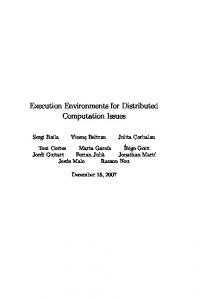
To understand the problems that prevent a distributed execution using FUML, we start with a brief overview of FUML’s architecture. FUML defines a UML model named execution model, that acts as a type model for models that store information about a running instance of an executed UML model. Figure 1 shows a small excerpt of FUML’s execution model. The elements in the execution model (e.g., operations) are annotated with their respective Java codes. A Java-based execution machine can be generated from this annotated execution model. extensionalValues
Locus
0..*
instantiate(type : UML::Class) : Object ActivityNodeActivationGroup activate(nodes : ActivityNode [0..*], edges : ActivityEdge [0..*])
activationGroup
ExtensionalValue Object
1 0..*
edgeInstances
Execution
ActivityEdgeInstance 0..*
nodeActivations ActivityNodeActivation
receiveOffer() fire(incomingTokens : Token [0..*])
0..* Token
heldTokens
sendOffer(tokens : Token [0..*]) 1 target 1 source
ActivityExecution execute()
Java implementation of this operation: Activity activity = (Activity)(this.getTypes().getValue(0)); this.activationGroup = new ActivityNodeActivationGroup(); this.activationGroup.activate(activity.node, activity.edge); ...
Fig. 1. Excerpt of FUML’s execution model
In the FUML execution model, a Locus is responsible for instantiating classes from the executed UML model and for holding the instantiated Objects. FUML uses the visitor design pattern [14] to add operations (that define the operational semantics) to classes in the UML meta model. A visitor class (for example, those
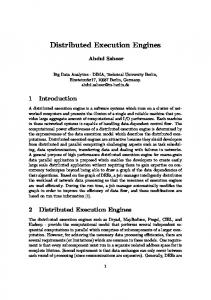
named *Execution, and *Activation) exists for each supported UML concept. An ActivityExecution represents a single execution of a UML::Activity (e.g., the behavior of a UML::Class from the executed UML model). An ActivityNodeActivation represents an execution of a UML::ActivityNode. Specializations of the abstract class ActivityNodeActivation exist in FUML for the different types of ActivityNodes in UML (e.g., DecisionNode, and Action). Since UML activity diagrams are based on Colored Petri nets [15, 11], FUML makes use of the essential Petri net concepts like places, transitions, and tokens. ActivityNodeActivations are the places and can hold different types of Tokens. ActivityEdgeInstances offer these Tokens from their source to their target ActivityNodeActivation. ActivityEdgeInstances act as Petri net transitions. Besides the problem that FUML’s implementation does not provide remote access to the execution model, there are two further issues that prevent a distributed execution. First, since access to the FUML execution model instance is not protected by any locking or synchronization mechanism, the existing Javabased implementation must fail in a distributed and concurrent environment due to data corruption (P1). Second, FUML uses synchronous, sequential operation calls to propagate tokens [16]. Thus, the state of the running model instance is spread across the call stack of the machine (e.g., a JVM) that executes the FUML implementation, and the corresponding instance of FUML’s execution model (P2). This contradicts traditional Petri net semantics, where the state of the Petri net is solely defined by the number of tokens in each place. Fig. 2 shows an example of a small UML activity diagram and the required interactions of the execution model objects (some omissions are made for better readability). Each of the non-UML arrows from the untyped lifelines towards nodes and edges of the activity diagram denotes the UML element that corresponds to an untyped lifeline.
A
sd
: ActivityNodeActivationGroup activate
receiveOffer
:
:
:
B
:
:
:
:
sendOffer receiveOffer receiveOffer sendOffer sendOffer receiveOffer
Fig. 2. Activity diagram and behavior realization in FUML
A call of receiveOffer transfers tokens from one node to another. Using this design to suspend (after action A) and to resume execution later (at the
workstation of another team member) requires to preserve the call stack. Another problem is that large activity diagrams or activity diagrams with cycles may lead to an overflowing stack due to the recursive receiveOffer calls.
3
Distributed Execution Machine Architecture
This section presents our solutions to the two above mentioned FUML problems that prevent a distributed execution, and it discusses FUML extensions to meet all of the requirements for a PEX. 3.1
Shared Access to the Execution Model
To fulfill requirement R1 (shared execution model access), we use the Connected Data Objects (CDO) model repository [17] to manage our execution model instance. As part of the Eclipse Modeling Framework (EMF) [18], CDO provides transparent access to a shared model in a network, as well as transactions for safe model manipulations in distributed environments. With CDO we can share the state of a running software process instance in a network. 3.2
Synchronized Access to the Execution Model
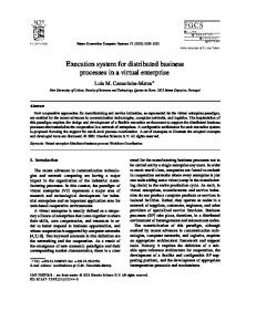
Transactions are a precondition to solve the FUML problem P1 (synchronized execution model access) in the Java-based implementation. However, their use requires changes to the operational semantics of FUML, because some of the essential Petri net properties [15] need to be respected. First, it must be an atomic operation to fire a transition (to transfer a number of tokens from the source node(s) to the target node(s)). Second, different transitions may fire concurrently. To reflect these properties, we use CDO transactions to isolate firing of single ActivityEdges (transitions). This includes the receiveOffer call to the target ActivityNodeActivation, which in turn includes execution of the behavior of the target node. Thus, moving tokens from one ActivityNodeActivation to another is now an atomic operation on an execution model instance. This solves the FUML problem P1 (synchronized execution model access). To solve the problem P2 (the execution state spread across the call stack and the execution model), we substitute FUML’s synchronous, sequential receiveOffer calls (see Fig. 2) with asynchronous calls performing basic Petri net operations. This can be done, because the state of a Petri net is solely defined by the number of tokens in each place. The information stored on the call stack is redundant. Instead of the preceding receiveOffer calls, our implementation triggers the firing of transitions by means of system events (different from events modeled in an SDP). Examples are user inputs, time events, and CDO events upon manipulation of the execution model instance. Depending on the type of event, the execution machine checks for transitions that can fire, and then fires them
in a single transaction. Figure 3 shows how a model changed event is handled, if A holds one token and the edge towards B is ready to fire.
A sd
: SessionListener
: Executor
model changed run
: ActivityNodeActivationGroup
B
e:
b:
startTransaction step
findEdgesWithOffers : [e] getTarget : b receiveOffer
commitTransaction … triggers a further model changed event, which can be handled by any SessionListener on any node.
Fig. 3. Activity diagram and behavior realization in eSPEM
Many CDO transactions can manipulate the execution model instance concurrently, if there are different source and target nodes (places) involved. If the same source or target node is involved, it is guaranteed that at most one transaction can be committed. The other transactions are rolled back. This ensures a correct number of tokens on each place. With these changes to FUML, we fix both problems and make the execution machine useful in distributed and concurrent environments. By using system events to trigger the firing of ActivityEdges, we also fulfilled requirement R2 (suspending and resuming execution on different (network) nodes), because these system events can be handled by any node in the network. After an event is handled, the node automatically suspends execution. 3.3
Human Interaction
To meet requirement R3 (human interaction), FUML has to be extended. This is due to a different focus of UML activities and actions, which are normally used to transform inputs into outputs, and must be modeled completely in order to be executable. In contrast to that, one of the essential properties of software processes is a usually incomplete formal description of their behavior. A process designer stops modeling the behavior of activities and tasks at some level of granularity. Instead, the process designer uses either natural language to describe the activities and tasks, or simply assumes that the project staff knows what to
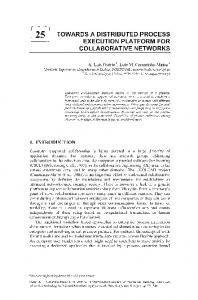
do in the course of the activities and tasks. In order to execute a software process modeled in that way, a tight interaction between the PEX and the project staff is required [1, 19]. That is, the PEX is responsible to support the project staff by planning and controlling their work according to the behavior model. In opposition to the PEX, the project staff carries out the actual creative work of a software process. To support this scenario, a PEX must be able to pass control of the software process execution over to project staff and take back control when they are finished with their tasks. However, this is out of FUML’s scope. To gain support for interaction with project staff that also fits into our distributed execution concept, we added to FUML an abstract class Request and some specializations of this class (see Fig. 4). Locus 0..*
requestPool source
Request isFulfilled() : Boolean
DecisionRequest 0..1
0..1
ObtainObjectReferenceRequest 0..1
result
ActivityNodeActivation suspend(r : Request) resume(r : Request) ExecutionRequest
result
0..1
target
Object
Value 0..1
classifier
inputParameterValues
Classifier (from eSPEM)
0..*
ParameterValue
Fig. 4. Requests in our Execution Model
Execution may be suspended at any ActivityNodeActivation. Suspending adds a pending Request to the requestPool of the Locus that (transitively) contains the ActivityNodeActivation. The project staff handles these Requests by editing their properties through the graphical user interface of the PEX. Editing Requests is secured by CDO transactions and thus can take place concurrently on any of the workstations. Once a Request is fulfilled, it is removed from the Locus and execution resumes at the ActivityNodeActivation that is the source of the Request. Let us discuss the three subtypes of Requests now. A DecisionRequest is used whenever no input value for the corresponding DecisionNode can be determined automatically. For example, a Role can be modeled [10] to choose the value for a DecisionNode as shown in Fig. 5 with one of the UML behavior modeling extensions available in eSPEM. At runtime, the PEX can offer these decisions to the ProductOwner who can choose a Value (the string Yes) as response to the DecisionRequest (see Fig. 5) through the context menu of our PEX. The PEX then selects the outgoing edge of the DecisionNode. An ObtainObjectReferenceRequest is used whenever an Object (e.g., an instance of a Task or a WorkProduct) is required as input for an Action but cannot be determined automatically. This is a quite common case when tasks are
Release Product? ... RoleUse Product Owner
[Yes]
...
[No]
...
decides ►
Fig. 5. Decision Modeled with eSPEM and DecisionRequest at Runtime
planned in advance and are dynamically selected for later execution. A project member may select an appropriate object (e.g., a pre-planned Task) that conforms to the classifier. The PEX then uses the selected object as an input to perform the Action. An ExecutionRequest is used whenever an ExecuteWorkAction is invoked and the WorkDefinition that shall be executed has no behavior modeled. In this case control over the execution of the target WorkDefinition is passed to the project staff. When the staff marks the WorkDefinition as finished, control is passed back to the PEX. With these extensions of FUML, we meet requirement R3: interaction with project staff. Requests also work in the distributed environment when handling them in CDO transactions. 3.4
Instantiation
A reasonable PEX must manage a lot of master data (for example, time spent on a task). In order to adapt to the needs of different teams and organizations (requirement R4), this data must be customizable. For example, one organization might use a PEX to track the time spent on tasks. Another organization may use a separate time-tracking software. Thus, it must be customizable whether all tasks have an attribute timeSpent and automatically track the time, or not. FUML’s generic instantiation mechanism cannot fulfill this requirement, because it only works with attributes modeled in the instantiated model. To understand the problem, we discuss FUML’s instantiation in more detail below. Software modeling and execution using (F)UML, as well as software process modeling and execution, are engineering domains that make use of several levels of (ontological) classification [20]. For an example see Fig. 6. The model representing the language definition (UML meta model) is an ontological type model for system models. In the same manner, a system model is an ontological type model for models that form the state of running system (instance models). To gain support for the three levels of ontological classification, FUML uses an orthogonal dimension of classification (linguistic classification) as proposed by the orthogonal classification architecture (OCA) [21]. Fig. 6 shows these orthogonal dimensions. FUML uses the prototypical concept pattern [20] to implicitly weave-in the class Object during linguistic instantiation. Therefore, Object implicitly is the base class of all classes modeled in the system model.
Execution model Object «linguistic» Class
Person
John W. «ontological» «ontological» Language (UML) System model Instance model
Fig. 6. Classification Levels used in UML/FUML
As a result, all instantiated elements in the instance model share the same base attributes and behavior of Object. This pattern can also be found in several object-oriented programming languages like Java or C#. During instantiation, FUML creates slots to hold the additional attribute values as modeled in the system model. However, there is no way to customize the base attributes and behavior of Object in FUML. The only way to do this is to explicitly model these attributes in the process model for every class (for example, by specializing an abstract class). This is a cumbersome, repetitive and error-prone task. The same problem occurs when FUML is used for software process execution. Missing customization support also leads to non-reusable standard process models, because they would be polluted with data specific to an organization or project. In order to fulfill requirement R4, we add support for customization of base attributes and behavior. We create an extensible type model for the master data called runtime model, which is an extension of FUML’s execution model. The users of the PEX can optionally extend the runtime model with a type model (runtime model extension). Figure 7 shows the runtime model (extension) in eSPEM’s classification hierarchy. Our runtime model provides the base attributes and behavior of the instantiable language constructs in eSPEM for example TaskDefinition and WorkProduct. These attributes are required by our PEX in order to work properly. In contrast to FUML, elements from the process model are not (ontologically) instantiated by instantiating a generic class (Object) from the execution model. Instead, when executing a process model, a type model called process runtime model is created on-the-fly by a configurable model-to-model (M2M) transformation. During this transformation, classes from our runtime model (or a runtime model extension) are woven-in as base classes for the classes from the process runtime model. The used base class from the runtime model (extension) is determined by the type of the corresponding process model element and the configuration of the transformation. For example, BaseTaskInstance (or BaseTaskInstanceExt) is configured as base class for all instances of TaskDefinition. Therefore, these instances share all the attributes and the behavior inherited from BaseTaskInstance (or BaseTaskInstanceExt). The behavior of the base classes can be implemented by the users of the PEX, for example, using a programming language. We use EMF models for linguistic instantiation. Thus, additional behavior of classes in a runtime model extension can be added by implementing methods in the EMF-generated Java code. For convenience, the Java
Execution Model
Runtime Model
Object BaseTaskInstance effort : Integer
Runtime Model Extension BaseTaskInstanceExt (optional, user definable) timeSpent : Real
Process Runtime Model M2M Transformation TaskDefinition «ontological» Language (eSPEM)
«TaskDefinition» Elicit Requirements expectedNum : Integer Process Model
Elicit Requirements expectedNum : Integer «linguistic» : Elicit Requirements
«ontological»
effort = 8 timeSpent = 7.8 expectedNum = 10 Process Instance
Fig. 7. Classification Levels used in eSPEM
code generated for a process runtime model is transparently distributed to all workstations. With the concept presented in this section, we fulfill requirement R4: support for customization of base attributes and behavior. By weaving-in customizations contained in a runtime model extension as an aspect, there is no need to pollute SDP models with this data. Therefore, standard software process models can be easily reused by different teams and organizations.
4
Evaluation
To test our FUML-based implementation of eSPEM’s operational semantics, we have implemented a test suite. Each test in this suite uses a small process model to test a specific language construct, for example, DecisionNode, ForkNode, or ExecuteActivityAction. In addition to the functional test, we also test some non-functional properties like maximum execution time. 4.1
Exemplary SDP
In addition to these tests that focus on functionality of individual language constructs, we have evaluated our PEX by executing an exemplary SDP in a controlled environment. The used SDP is based on Scrum [22] with changes to simplify automated testing. Scrum is an iterative incremental SDP. An iteration usually takes 4 weeks and is called sprint. At the beginning of each sprint, the features are selected that form the product increment developed in that sprint. Then, activities are planned to implement these features. Figure 8 shows the
behavior of Implement Feature (with its sub-tasks) used to implement one feature. The rest of the exemplary SDP consists of an infinite loop that instantiates and executes several Implement Feature activities.
Implement Feature Exec: Understand Requirements
Complete?
Exec: Test Exec: Code
◄ decides
[No]
RoleUse Team
[Yes]
Fig. 8. Behavior of Implement Feature in the Exemplary SDP
4.2
Test Setup
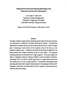
Our test setup consists of 6 PCs connected by a local network. One PC acts as the server for the execution model instance and the execution machine. The other 5 PCs act as clients and simulate human interaction with the execution machine by answering Requests. Tests are performed with 1, 2, 3, 10, and 20 execution machine clients running simultaneously on each of the 5 client PCs to simulate different project sizes. We measure the execution time of each transaction on the execution model instance. The benchmark considers five different types of transactions. Server: The transactions that isolate the firing of transitions. These transactions are usually faster, because the execution machine is running within the same JVM as the execution model instance server (local loopback). Planning: These transactions isolate instantiation of Implement Feature activities on a client. Understand transactions isolate execution of an Understand Requirements task by a client. In the same way, Test and Code isolate execution of Test and Code tasks. The decision whether a feature is completely implemented or not, is isolated by Finished transactions. The average execution time for these transactions with 5, 10, 15, 50, and 100 execution machine clients concurrently working on the execution model instance, is shown in Fig. 9. Our tests show that execution time of typical transactions is below 100 ms. Hence, we consider this a sufficient response time for human interaction, even if the PEX is under high load with connections from many clients. These clients are running automated tests that handle requests within a second. In contrast, humans are considered to have a few interactions per hour with a PEX.
5
Related Work
Many authors have identified executability as highly relevant for (software) process modeling. Although first descriptions of software processes with process
Average Execution Time
100 ms 90 ms 80 ms 70 ms 60 ms 50 ms 40 ms 30 ms 20 ms 10 ms 0 ms
5 10 15 50 100 Server
Planning
Underst. Test Transaction Type
Code
Finished
Fig. 9. Average Execution Time vs. Transaction Type for Different Numbers of Clients
programming languages were executable [1] (some even supported distributed execution; see [2]), they had limited impact in industry due to their complex formalisms or low level of abstraction [13]. Therefore, below we focus on approaches that are based on standardized high-level modeling languages. BPMN [23] or WS-BPEL [24] and its extension for People [25] were created to model and execute business processes. Although they provide a reasonable behavior modeling and execution concept, they do not provide essential concepts from SDPs, like roles, guidelines, responsibility assignments, and tools. These concepts have to be modeled by means of BPEL variables or cannot be modeled at all [19]. Thus, SDP descriptions with business process languages are incomplete and limit the support a PEX can provide when executing them. Bendraou et al. [26] present xSPEM and focus on SDP validation with timed Petri nets. xSPEM also adds events for SPEM activities but lacks a fine-grained behavior modeling approach with decisions and task scheduling. Furthermore, no tool is provided to support direct execution of xSPEM-based models. Seidita et al. [27] extend SPEM to support the modeling of agent oriented methodologies [28] but do not focus on executability. UML4SPM [29] extends SPEM 1.1 with UML 2.0 behavior modeling concepts. There are two ways to make UML4SPM-based models executable. First, UML4SPM is mapped to WS-BPEL for enactment support [19]. As mentioned above, business processes lack some of the essential concepts of software processes, for example, roles, and guidelines. Moreover, the language WS-BPEL does not support human interaction during execution. Second, the operational semantics of UML4SPM is defined based on FUML. In [30], FUML’s execution model concept is woven into UML4SPM using Kermeta [31]. Another implementation of UML4SPM based on FUML and Java is presented in [9]. Both implementations allow for a direct simulation and execution of UML4SPM-based process models, but they lack distributed execution support. Di Nitto et al. [32] model SDP’s with a UML 1.3-based framework. They do not use a dedicated meta model for language definition, but rather use plain UML. The proposed framework elements (e.g., Activity) are all instances of
the UML meta class Class. SDPs are modeled by specializing the framework elements. This approach achieves executability by generating Java code from the diagrams (Class, Activity, and State Machine diagrams) used to describe an SDP. However, it remains vague how essential aspects of software processes (for example, precedence of activities) are translated. Another major drawback is the lack of a real modeling language definition. The sole use of UML classes may also confuse process modelers because all model elements have the same notation and semantics. Chou [33] uses a subset of UML 1.4 activity and class diagrams to model SDPs graphically. He proposes a supplemental low-level object-oriented process programming language to execute SDPs. However, the executable code must be manually derived from the diagrams. Besides SPEM, there is another standardized meta model driven approach for describing development methodologies: the ISO/IEC standard SEMDM [5]. However, SEMDM lacks a fine-grained behavior modeling concept and no execution support is currently provided. Engels et al. [34] show how plain UML 2.0 can be used for process modeling. However, since essential concepts of SDP modeling are missing in UML (e.g., work products and responsibility assignments) the resulting SDPs are incomplete and imprecise so that support by a PEX must be limited. Other approaches use UML and extensions through stereotypes for SDP modeling, for example [35] and the SPEM standard [6] itself, which also defines a UML profile. This allows to use behavior modeling concepts from UML with standard UML tools for modeling SDPs. Additionally, at least parts of the models could be executed using FUML. However, all of these approaches suffer from the fact that stereotypes change the semantics of the UML elements they are applied to but have no influence on the language structure as defined by the UML meta model. This results in two drawbacks: First, the SDP modeling language structure has to be re-implemented, for example, as constraints for the stereotypes. Second, the operational semantics of the stereotypes has to be defined and integrated with FUML in order to provide reasonable execution support. As outlined above, FUML also has a different focus and does not provide essential concepts like human interaction. Benyahia et al. [16] extend FUML to reflect additional requirements on the execution semantics for real-time systems (e.g., scheduling, and concurrency). The authors highlight similar problems with FUML’s Java mapping using synchronous, sequential method calls for token and event propagation. They introduce the class Scheduler in the execution model that is responsible to dispatch actions and therefore break the strictly sequential execution in FUML. However, they do not support distributed execution. Regarding instantiation, several other approaches exist that enable multilevel modeling. Atkinson and K¨ uhne discuss some of them in [21]. We briefly discuss the two most prominent of them below. The powertype pattern [36] (used by SEMDM [5, 37]) uses a special relationship between two classes (powertype and partitioned type). The powertype
instantiates objects that form the process model. In conjunction with a specialization of the partitioned type, these objects form a so called clabject. The name is derived from class and object, because a clabject has both a class facet and an object facet. Objects at process instance level are instantiated from the class facet. The powertype pattern still uses one level of instantiation (shallow instantiation), but with generalization relationships crossing the ontological instantiation layers. This violates a strict separation of classification levels as requested by strict meta modeling [20] and may lead to confusion [38]. FUML and our approach use an instantiation concept well aligned with orthogonal classification architecture that also conforms to the rules of strict meta modeling. Atkinson and K¨ uhne [21, 39] present another approach to multi-level modeling called deep instantiation, which allows to annotate elements of type models (for example, classes and attributes) with a non-negative number called potency. With each instantiation step, potency is decreased by 1. An element with potency above 0 can be further instantiated. With potency 0, it behaves like a normal object or attribute instance. Although this is a generic approach for multi-level classification, its application to established standards like UML and SPEM is problematic [40, 41].
6
Conclusion and Future Work
In this paper, we have identified why pure FUML cannot be used to execute software process models to drive realistic projects with large and distributed teams. The presented FUML extension supports distributed execution with synchronized access to a shared execution model instance. In addition, it supports suspending and resuming execution on different nodes, as well as requests to interact with project staff. Our extension of FUML’s instantiation concept allows organizations and projects to easily weave-in their specific attributes and behavior in order to tailor the execution machine to their needs. As a result, the extended FUML can be used to enact reusable standard software process models in realistic projects. Our work is also useful for other PMLs based on UML behavior modeling concepts and for a concurrent execution of UML models in general. With small modifications of the M2M transformation, our instantiation concept could also be used to weave-in specific behavior for UML elements with stereotypes and therefore implement the semantics of the stereotypes. In the future, we will focus on implementing the operational semantics of state machines, which are currently missing in both FUML and our FUMLextension. We also plan to enhance our PEX to integrate existing tools and their data formats. Another topic of our future work is process evolution: Process evolution is considered crucial if a model is executed over a long time (duration of the development project) and the process model or the runtime extension model has to be changed, for example, due to an error in the process model. Process evolution should allow for an (semi-)automatic adaptation of the process instance model to the changed process model or runtime extension model.
References 1. Osterweil, L.J.: Software processes are software too. In: Proc. 9th Intl. Conf. on Softw. Eng., Monterey, CA. (Apr. 1987) 2–13 2. Zamli, K., Lee, P.: Taxonomy of Process Modeling Languages. In: Proc. ACS/IEEE Intl. Conf. on Computer Sys. and Appl., Beirut, Lebanon. (Jun. 2001) 435–437 3. Acu˜ na, S.T., Ferr´e, X.: Software Process Modelling. In: Proc. World Multiconf. on Systemics, Cybernetics and Informatics, Orlando, FL. (Jul. 2001) 237–242 4. Bendraou, R., Jezequel, J.M., Gervais, M.P., Blanc, X.: A Comparison of Six UML-Based Languages for Software Process Modeling. IEEE Trans. Softw. Eng. 36 (2010) 662–675 5. ISO/IEC: ISO/IEC 24744:2007 – Software Engineering – Metamodel for Development Methodologies. (Feb. 2007) 6. Object Management Group: Software & Systems Process Engineering Meta-Model Specification v2.0. (Apr. 2008) 7. Object Management Group: UML: Infrastructure v2.2. (Feb. 2009) 8. Almeida da Silva, M., Bendraou, R., Blanc, X., Gervais, M.P.: Early Deviation Detection in Modeling Activities of MDE Processes. In: Proc. 13th Intl. Conf. Model Driven Eng. Lang. and Sys., Oslo, Norway. Volume 6395 of LNCS. (Oct. 2010) 303–317 9. Bendraou, R., Jez´equ´el, J.M., Fleurey, F.: Achieving process modeling and execution through the combination of aspect and model-driven engineering approaches. J. of Softw. Maintenance and Evolution: Research & Practice Preprint (2010) n/a 10. Ellner, R., Al-Hilank, S., Drexler, J., Jung, M., Kips, D., Philippsen, M.: eSPEM - A SPEM Extension for Enactable Behavior Modeling. In: Proc. 6th European Conf. Model. Foundations and Appl., Paris, France. Volume 6138 of LNCS. (Jun. 2010) 116–131 11. Object Management Group: UML: Superstructure v2.2. (Feb. 2009) 12. Object Management Group: Semantics of a Foundational Subset for Executable UML Models v1.0 Beta 3. (Mar. 2010) 13. Gruhn, V.: Process Centered Software Engineering Environments – A Brief History and Future Challenges. Annals of Softw. Eng. 14(1-4) (2002) 363–382 14. Gamma, E., Helm, R., Johnson, R., Vlissides, J.: Design Patterns: Elements of Reusable Object-Oriented Software. Addison-Wesley (1994) 15. Jensen, K.: Coloured Petri nets. Springer (1995) 16. Benyahia, A., Cuccuru, A., Taha, S., Terrier, F., Boulanger, F., G´erard, S.: Extending the Standard Execution Model of UML for Real-Time Systems. In: Proc. 7th IFIP TC 10 Working Conf. Distributed, Parallel and Biologically Inspired Sys., Brisbane, Australia. (Sep. 2010) 43–54 17. Eclipse Foundation: Connected Data Objects (CDO) Model Repository, http://www.eclipse.org/cdo/ 18. Eclipse Foundation: Eclipse Modeling Framework (EMF), http://www.eclipse.org/modeling/emf/ 19. Bendraou, R., Sadovykh, A., Gervais, M.P., Blanc, X.: Software Process Modeling and Execution: The UML4SPM to WS-BPEL Approach. In: Proc. 33rd EUROMICRO Conf. on Softw. Eng. and Adv. Appl., L¨ ubeck, Germany. (Aug. 2007) 314–321 20. Atkinson, C., K¨ uhne, T.: Processes and products in a multi-level metamodeling architecture. Intl. J. Softw. Eng. and Knowledge Eng. 11(6) (2001) 761–783 21. Atkinson, C., K¨ uhne, T.: The essence of multilevel metamodeling. In: Proc. 4th Intl. Conf. on UML, Modeling Lang., Concepts, and Tools, Toronto, Canada. (Oct. 2001) 19–33
22. 23. 24. 25.
26.
27.
28. 29.
30.
31.
32.
33.
34.
35.
36. 37.
38. 39. 40.
41.
Schwaber, K.: Agile Project Management with Scrum. Microsoft Press (2004) Object Management Group: Business Process Modeling Notation v1.2. (Jan. 2009) OASIS: Web Services Business Process Execution Language v2.0. (Apr. 2007) Active Endpoints Inc., Adobe Systems Inc., BEA Systems Inc., IBM Corp., Oracle Inc., and SAP AG: WS-BPEL Extension for People (BPEL4People), v1.0. (Jun. 2007) Bendraou, R., Combemale, B., Cr´egut, X., Gervais, M.P.: Definition of an Executable SPEM 2.0. In: Proc. 14th Asia-Pacific Softw. Eng. Conf., Nagoya, Japan. (Dec. 2007) 390–397 Seidita, V., Cossentino, M., Gaglio, S.: Using and Extending the SPEM Specifications to Represent Agent Oriented Methodologies. In: Proc. 9th Intl. Workshop Agent-Oriented Softw. Eng., Estoril, Portugal. (May 2008) 46–59 Henderson-Sellers, B., Giorgini, P.: Agent-Oriented Methodologies. Idea Group (2005) Bendraou, R., Gervais, M.P., Blanc, X.: UML4SPM: A UML2.0-Based Metamodel for Software Process Modelling. In: Proc. 8th Intl. Conf. Model Driven Eng. Lang. and Sys., Montego Bay, Jamaica. Volume 3713 of LNCS. (Oct. 2005) 17–38 Bendraou, R., Jez´equ´el, J.M., Fleurey, F.: Combining Aspect and Model-Driven Engineering Approaches for Software Process Modeling and Execution. In: Proc. Intl. Conf. on Softw. Process, Vancouver, Canada. Volume 5543 of LNCS. (May 2009) 148–160 Muller, P.A., Fleurey, F., Jez´equ´el, J.M.: Weaving Executability into ObjectOriented Meta-languages. In: Proc. 8th Intl. Conf. Model Driven Eng. Lang. and Sys., Montego Bay, Jamaica. Volume 3713 of LNCS. (Oct. 2005) 264–278 Di Nitto, E., Lavazza, L., Schiavoni, M., Tracanella, E., Trombetta, M.: Deriving executable process descriptions from UML. In: Proc. 24th Intl. Conf. on Softw. Eng., Orlando, FL. (May 2002) 155–165 Chou, S.C.: A Process Modeling Language Consisting of High Level UML-based Diagrams and Low Level Process Language. J. of Object Technology 1(4) (2002) 137–163 Engels, G., F¨ orster, A., Heckel, R., Th¨ one, S.: Process Modeling using UML. In Dumas, M., van der Aalst, W., ter Hofstede, A., eds.: Process-Aware Information Sys., John Wiley & Sons (2005) 85–117 J¨ ager, D., Schleicher, A., Westfechtel, B.: Using UML for Software Process Modeling. In: Proc. 7th European Softw. Eng. Conf., Toulouse, France. (Sep. 1999) 91–108 Odell, J.J.: Power types. J. of Object-Oriented Programming 7(2) (1994) 8–12 Henderson-Sellers, B., Gonzalez-Perez, C.: The Rationale of Powertype-based Metamodelling to Underpin Software Development Methodologies. In: Proc. 2nd Asia-Pacific Conf. on Conceptual Model., Newcastle, Australia. (Jan. 2005) 7–16 K¨ uhne, T.: Contrasting classification with generalisation. In: Proc. 6th Asia-Pacific Conf. on Conceptual Model., Wellington, New Zealand. (Jan. 2009) 71–78 Atkinson, C., K¨ uhne, T.: Rearchitecting the UML infrastructure. ACM Trans. Model. Comput. Simul. 12(4) (2002) 290–321 Gutheil, M., Kennel, B., Atkinson, C.: A systematic approach to connectors in a multi-level modeling environment. In: Proc. 11th Intl. Conf. on Model Driven Eng. Lang. and Sys., Toulouse, France. (Oct. 2008) 843–857 Atkinson, C., Gutheil, M., Kennel, B.: A flexible infrastructure for multilevel language engineering. IEEE Trans. Softw. Eng. 35 (2009) 742–755