A FUNCTION-BEHAVIOUR-STRUCTURE ONTOLOGY OF PROCESSES JOHN S GERO 1 AND UDO KANNENGIESSER2
Corresponding author: Udo Kannengiesser Email:
[email protected] NICTA Locked Bag 9013 Alexandria NSW 1435 Australia Tel: +61-2-8374 5231 Fax: +61-2-8374 5520 Short title: An FBS ontology of processes Total length of manuscript: 37 pages Number of tables: 0 Number of figures: 16 1 2
Krasnow Institute for Advanced Study, George Mason University, USA NICTA, Australia
2
A FUNCTION-BEHAVIOUR-STRUCTURE ONTOLOGY OF PROCESSES Abstract. This paper presents how the function-behaviour-structure (FBS) ontology can be used to represent processes despite its original focus on representing objects. The FBS ontology provides a uniform framework for classifying processes and includes higher-level semantics in their representation. We show that this ontology supports a situated view of processes based on a model of three interacting worlds. A framework – the situated FBS framework – is then used to describe the situated design of processes. Keywords: Process ontology, function-behaviour-structure framework, situatedness
1. Introduction
3
Ontologies are structured conceptualisations of a domain in terms of a set of entities in that domain and their relationships. They provide uniform frameworks to identify differences and similarities that would otherwise be obscured. In the design domain, a number of ontologies have been developed to represent objects, specifically artefacts (Chandrasekaran and Josephson 2000; Stone and Wood 2000; Kitamura et al. 2004; IAI 2006). They form the basis for a common understanding and terminological agreement on all relevant properties of a specific artefact or class of artefacts. Ontologies can then be used to represent the evolving states of designing these artefacts or as knowledge representation schemas for systems that support designing. Design research is a field that has traditionally shown particular interest in explicit representations of processes besides objects. A number of process taxonomies have been created that classify different design methods (e.g. Cross (1994), Hubka and Eder (1996)). However, most of this work has not been based on process ontologies, which makes comparison of the different taxonomies difficult. Ontologies are richer than taxonomic class hierarchies, as they provide definitions and constraints for an entity’s properties and relationships. Some of the efforts towards stronger ontological foundations for process representation have been driven by the need to effectively plan and control design and construction processes. For example, recent work on 4D CAD systems links 3D object models to project schedules (Haymaker and Fischer 2001). A large number of process ontologies and representations have been developed, with varying degrees of domain- or task-specificity. For example, IDEF0 (NIST 1993) is a high-level ontology for modelling industry processes at any level of detail, distinguishing between input, control, output and mechanism. Another, more recent high-level ontology is PSL (NIST 2000). PERT (Wiest and Levy 1977) is a process representation primarily used for scheduling tasks in projects. The Quirk Model (Motus and Rodd 1994) describes computational processes and their timing constraints to enable analysis and control of overall system speed. Most process ontologies and representations have a view of processes that is based on flows of activities and/or sequences of states. Semantics, capturing the processes’ applicability in a purposive
context, are generally not included in most process ontologies. Such semantics are needed to guide the 4
generation, analysis and evaluation of a variety of processes. As research increasingly focuses on automating parts of the selection or synthesis of processes, existing process ontologies provide inadequate representations for computational support. An ontology that supports semantics is based on the function-behaviour-structure (FBS) framework introduced by Gero (1990) that later became an ontology (Gero and Kannengiesser 2004). Its original focus was on representing artificial objects. In this paper we show how this focus can be extended to include processes. Our contribution thus consists of a novel interpretation and application of an existing ontology rather than a novel ontology of processes itself. Section 2 describes the basics of this approach and demonstrates how the FBS ontology can be used to classify processes. Section 3 develops a situated view of processes, which accounts for situation-specific changes in process representations at three levels: the function level, the behaviour level and the structure level. Section 4 presents a framework of situated process design, using a design optimisation process as an example. Section 5 concludes the paper.
2. The FBS Ontology 2.1. THE FBS VIEW OF OBJECTS
The FBS ontology provides three high-level categories for the properties of an object: 1. Function (F) of an object is defined as its teleology (“what the object is for”), which is largely domain-dependent. 2. Behaviour (B) of an object is defined as the attributes that can be derived from its structure (“what the object does”). Most instances of behaviour are domain-dependent. 3. Structure (S) of an object is defined as its components and their relationships (“what the object consists of”). The structure of most objects can be described in terms of geometry, topology and material. Humans construct connections between function, behaviour and structure through experience and through the development of causal models based on interactions with the object. Specifically, function is ascribed to behaviour by establishing a teleological connection between the human’s goals and
observable or measurable effects of the object. Behaviour is causally connected to structure, i.e. it can 5
be derived from structure using physical laws or heuristics. There is no direct connection between function and structure (de Kleer and Brown 1984). The generality of the FBS ontology allows for multiple views of the same object. This enables the construction of different models depending on their purpose. For example, an architectural view of a building object includes different FBS properties than a structural engineering view. This is most striking for the building’s structure: Architects typically view this structure as a configuration of spaces, while engineers often prefer a disjoint view based on floors and walls. Multiple views can also be constructed depending on the required level of aggregation. This allows modelling objects as assemblies composed of sub-assemblies and individual parts. Each of these components can again contain other sub-assemblies or parts. No matter which level of aggregation is required, the FBS ontology can always be applied. 2.2. THE FBS VIEW OF PROCESSES
Objects and processes have traditionally been regarded as two orthogonal views of the world. The difference between these views is primarily based on the different levels of abstraction involved in describing what makes up their structure. The structure of physical or virtual objects consists of representations of material, geometry and topology. These representations can be easily visualised and understood. Processes are more abstract constructs that include transitions from one state of affairs to another. The high-level categorisations provided by the FBS ontology create an integrative view that treats objects and processes in a uniform manner. This is possible because the FBS ontology does not include the notion of time. While on an instance level this notion is fundamental to the common distinction between objects and processes, on an ontological level there is no time-based difference between them. All states of any entity at any point in time can be described by a set of properties that can be classified as function, behaviour and structure.
6
The notion of function applies to any entity as it only accounts for the observer’s goals,
independent of the entity’s embodiment as an object or as a process. We will give examples of process functions in the following Sections. Behaviour relates to those attributes of an entity that allow comparison on a performance level rather than on a compositional level. Such performance attributes are representations of the effects of the entity’s interactions with its environment. Typical behaviours of processes are speed, rate of convergence, cost, amount of space required and accuracy. While process function and process behaviour are not fundamentally different to object function and object behaviour, process structure is clearly distinctive. It includes three components and two relationships, Figure 1.
Figure 1. The structure of a process. (i = input; t = transformation; o = output)
The components are •
an input (i),
•
a transformation (t) and
•
an output (o).
The relationships connect •
the input and the transformation (i – t) and
•
the transformation and the output (t – o).
2.2.1. Input (i) and Output (o) The input and the output structure elements represent properties of other entities in terms of their variables and/or their values. For example, the process of transportation changes only the values for the location of a (physical) object (e.g. the values of its x-, y- and z-coordinates). As the input and output contain the same variables here, such a process can be characterised as homogenous. Heterogenous processes, in contrast, use disparate variables as input and output. For example, the
process of electricity generation takes mechanical motion as input and produces electrical energy as 7
output. Input and output may refer not only to (properties of) objects but also to (properties of) other processes. For example, it is not uncommon for software procedures to accept the output of other procedures as their input or to return procedure calls as their output. All variables and values used as input and output of a process may refer to the function, behaviour or structure of other objects or processes. 2.2.2. Transformation (t) A common way to describe the transformation of a process is in terms of a plan, a set of rules or other procedural descriptions. A typical example is a software procedure that is expressed in source code or as a UML3 activity diagram. Such descriptions are often viewed as a collection of subordinate processes. In the software example, this is most explicit when a procedure calls other procedures that are possibly located in other program components or other computers. Every sub-process can again be modelled in terms of function, behaviour and structure. 2.2.3. Relationships The relationships between the three components of a process are usually uni-directional from the input to the transformation and from the transformation to the output. For iterative processes the t – o relationship is bi-directional to represent the feedback loop between the output and the transformation. 2.2.4. Some Process Classifications Based on the FBS Ontology The FBS view of processes provides a means to classify different instances of design processes according to differences in their function, behaviour or structure. (To avoid confusion, we will from now on use the terms “object function”, “object behaviour” and “object structure” whenever we refer to objects. In all other cases, the default assumption will be that the terms “function”, “behaviour” and “structure” refer to processes.) Take Gero’s (1990) eight fundamental classes of processes involved in designing; they can be distinguished by differences in their input and output. For example, while synthesis is a transformation of expected object behaviour (i) into object structure (o), analysis 3
Unified Modeling Language
transforms object structure (i) into object behaviour (o). Within each of these fundamental processes 8
we can identify different instances if we reduce the level of abstraction at which input and output are specified. For example, different instances of the process class analysis can be defined based on the specific kind of output they produce: stress analysis computes stress (o), thermal analysis computes temperature (o), cost analysis computes cost (o), etc. Other process instances can be based on the transformation. For example, the synthesis of a design object can be carried out using a range of different transformations or techniques to map expected behaviour onto structure. Examples include case-based reasoning, genetic algorithms or gradient-based search methods. Other process classifications and taxonomies are similarly based on differences in structure. For example, Hubka and Eder (1996) distinguish between six sub-processes of designing, each of which specifies distinct abstraction levels describing their input and output. Processes can also be distinguished according to their behaviour and function. For example, design optimisation processes can be characterised on the basis of differences in their speed, differences in the amount of space they require or other behaviours. Another example has been provided by Sim and Duffy (1998), who propose a multi-dimensional classification of machine learning processes in design that can be mapped on structure and function of a process. Specifically, learning processes are grouped according to input knowledge and learning trigger (both i), knowledge transformers (t), output knowledge (o) and learning goal (F).
3. Situated FBS Representations of Processes 3.1. SITUATEDNESS
Designing is an activity during which designers perform actions in order to change their environment. By observing and interpreting the results of their actions, they then decide on new actions to be executed on the environment. This means that the designers’ concepts may change according to what they are “seeing”, which itself is a function of what they have done. One may speak of an “interaction of making and seeing” (Schön and Wiggins 1992). This interaction between the designer and the environment strongly determines the course of designing. This idea is called situatedness, whose foundational concepts go back to the work of Dewey (1896) and Bartlett (1932).
In experimental studies of designers, phenomena related to the use of sketches, which support this 9
idea, have been reported. Schön and Wiggins (1992) found that designers use their sketches not only as an external memory, but also as a means to reinterpret what they have drawn, thus leading the design in a new direction. Suwa et al. (1999) noted, in studying designers, a correlation of unexpected discoveries in sketches with the invention of new issues or requirements during the design process. They concluded that “sketches serve as a physical setting in which design thoughts are constructed on the fly in a situated way”. Gero and Fujii (2000) have developed a framework for situated cognition using agents, which describes the designer’s interpretation of their environment as interconnected sensation, perception and conception processes. Each of them consists of two parallel processes that interact with each other: A push process (or data-driven process), where the production of an internal representation is driven (“pushed”) by the environment, and a pull process (or expectation-driven process), where the interpretation is driven (“pulled”) by some of the designer’s current concepts, which has the effect that the interpreted environment is biased to match the current expectations. The environment that is interpreted can be external or internal to the agent. The situated interpretation of the internal environment accounts for the notion of constructive memory. The relevance of this notion in the area of design research has been shown by Gero (1999). Constructive memory is best exemplified by a paraphrase of Dewey by Clancey (1997): “Sequences of acts are composed such that subsequent experiences categorize and hence give meaning to what was experienced before”. The implication of this is that memory is not laid down and fixed at the time of the original sensate experience but is a function of what comes later as well. Memories can therefore be viewed as being constructed in response to a specific demand, based on the original experience as well as the situation pertaining at the time of the demand for this memory. Therefore, everything that has happened since the original experience determines the result of memory construction. Each memory, after it has been constructed, is added to the existing knowledge (and becomes part of a new situation) and is now available to be used later, when new demands require the construction of further memories. These new memories can be viewed as new interpretations of the augmented knowledge.
10
The advantage of constructive memory is that the same external demand for a memory can
potentially produce a different result, as newly acquired experiences may take part in the construction of that memory. Constructive memory can thus be seen as the capability to integrate new experiences by using them in constructing new memories. As a result, knowledge “wires itself up” based on the specific experiences it has had, rather than being fixed, and actions based on that knowledge can be altered in the light of new experiences. Situated designing, whether carried out by humans or a design system, uses first-person knowledge grounded in the designer’s interactions with their environment (Bickhard and Campbell 1996; Clancey 1997; Ziemke 1999; Smith and Gero 2005). This is in contrast to static approaches that attempt to encode all relevant design knowledge prior to its use. Evidence in support of first-person knowledge is provided by the fact that different designers are likely to produce different designs for the same set of requirements. And the same designer is likely to produce different designs at different points in time even though the same requirements are presented. This is a result of the designer acquiring new knowledge while interacting with their environment. Gero and Kannengiesser (2004) have modelled situatedness as the interaction of three worlds, each of which can bring about changes in any of the other worlds, Figure 2(a).
Figure 2. Situatedness as the interaction of three worlds: (a) general model, (b) specialised model for design representations (after Gero and Kannengiesser (2004)).
The external world is the world that is composed of representations outside the designer or design system. The interpreted world is the world that consists of the sensory experiences, percepts and concepts of the designer or design system. It is the internal representation of that part of the external world that the designer or design system interacts with. The expected world is the world imagined actions will produce. It is the environment in which the designer or design system predicts the effects of actions according to the current goals and
interpretations. The term “expected world” extends the notion of simple desirability by incorporating 11
goals that serve as “expected”, realistic benchmarks for actions. These three worlds are linked together by three classes of activities. Interpretation transforms variables which are sensed in the external world into the interpretations of sensory experiences, percepts and concepts that compose the interpreted world. Focussing takes some aspects of the interpreted world and uses them as goals for the expected world that then become the basis for the suggestion of actions. These actions are expected to produce states in the external world that reach the goals. Action is an effect which brings about a change in the external world according to the goals in the expected world. Figure 2(b) presents a specialised form of this view with the designer or design system (as the internal world) located within the external world and placing general classes of design representations into the resultant nested model. The set of expected design representations (Xei) corresponds to the notion of a design state space. This state space can be modified during the process of designing by transferring new interpreted design representations (Xi) into the expected world and/or transferring some of the expected design representations (Xei) out of the expected world. This leads to changes in external design representations (Xe), which may then be used as a basis for re-interpretation, changing the interpreted world. In Figure 2(b), both interpretation and constructive memory are represented as “push-pull” processes, as outlined earlier in this Section. The view of three worlds captures the idea that multiple (interpreted) views can be constructed from the same external world, and that multiple goals can arise from different views. Gaps between current goals and current (interpreted) views of the world then lead to individual actions aiming to reduce these gaps. 3.2. CONSTRUCTING MULTIPLE VIEWS FOR MULTIPLE PURPOSES
Gero and Kannengiesser’s (2004) three-world model can be used to construct situated FBS representations of processes 4. The main basis for creating a situated view is the distinction between the 4
While it is clearly the processes that are situated, in this paper we use the term “situated FBS representations of processes” as shorthand for “FBS representations of situated processes”.
external and the interpreted world. Locating function, behaviour and structure of a process in each of 12
these worlds, Figure 3, results in six ontological categories:
Figure 3. External and interpreted FBS representations of processes.
1. external function (Fe) 2. external behaviour (Be) 3. external structure (Se) 4. interpreted function (Fi) 5. interpreted behaviour (Bi) 6. interpreted structure (Si) Process representations of categories 4, 5 and 6 are generated via push-pull activities involving only the internal world (constructive memory) or both internal and external worlds (interpretation). Additionally, interpreted behaviour (Bi) can be generated by transforming interpreted structure (Si), and interpreted function (Fi) can be generated by transforming interpreted behaviour (Bi). 3.2.1. External vs. Interpreted Structure of a Process Most design ontologies cannot deal with different interpretations of a process, as they do not distinguish between external and interpreted worlds. Such interpretations are often required for representing process structure. This is due to a number of reasons. Many instances of external process structure (Se) are transient and time-based. Delineating the components of the process (i.e. input, transformation and output) from one another as well as from other entities in the external world then requires acts of discretisation from continuous flows of events according to the observer’s current knowledge and goals. For example, it is possible to view the intermediate results of an iterative process as part of its transformation or, alternatively, as part of its output. The kind of components of the process structure and the level of detail used to describe them are similarly dependent on the stance of the observer. One example, already mentioned in Section 2.2.2, is
the range of possible views of the transformation from a detailed procedural plan to an object or a 13
simple “black box”. There are also many examples for disparate views of the input and output of the same process. Take a pressing process in the automotive industry: A manufacturing engineer generally views the input and the output of this process in terms of geometry of the sheet steel to be transformed. In contrast, a costing expert typically views the input and the output of the same process in terms of (material, labour, etc.) cost and yield, respectively. Similar view-dependent examples have been presented by NIST (2004). 3.2.2. External vs. Interpreted Behaviour of a Process The distinction between external and interpreted worlds is also useful when dealing with the performance or behaviour of a process. This allows different observers to reason about different performance aspects of a process according to the current situation. For example, the cost of burning fuel might be important for the owner of a car; however, this cost is usually not directly relevant for the hitchhiker sitting on their passenger seat. Another example is the amount of memory space needed by a particular computational process. This behaviour is usually worth considering for users only if their hardware resources are limited for current purposes. The kind of interpreted behaviour (Bi) constructed is largely influenced by individual experience, and must therefore be clearly distinguished from external behaviour (Be). The kind of interpreted behaviour (Bi) that an observer is interested in also affects the way in which that observer interprets the structure that is responsible for causing that behaviour. This is the case when no external behaviour (Be) and no memories of previous interpreted behaviour (Bi) are available, and the interpreted behaviour (Bi) must be derived from interpreted structure (Si). If, for instance, the speed of a process is to be measured, then a structural description of the input and output of that process must be produced that contains references to some quantities and time units. If the amount of space required by the process is to be measured, then there must be a structural description that provides sufficient detail about the path of transformation for given inputs and outputs. 3.2.3. External vs. Interpreted Function of a Process
The need to separate the interpreted from the external world is most obvious for the function of a 14
process. Individual observers have the autonomy to interpret function according to their own goals and desires that are likely to differ from others. They may come up with various interpreted process functions (Fi), which may be independent of the constraints imposed by process structure and behaviour. For example, it is solely dependent on an observer’s previous experience or current goals if they ascribe the function “operate time-efficiently” to a manufacturing process, even though the exact speed of that process (as its interpreted behaviour (Bi)) or an explicit, external function (Fe) may be given. 3.3. CONSTRUCTING MULTIPLE PURPOSES FROM MULTIPLE VIEWS
Let us add the expected world to the interpreted and external world, Figure 4. The number of ontological categories now increases to nine: 1. external function (Fe) 2. external behaviour (Be) 3. external structure (Se) 4. interpreted function (Fi) 5. interpreted behaviour (Bi) 6. interpreted structure (Si) 7. expected function (Fei) 8. expected behaviour (Bei) 9. expected structure (Sei)
Figure 4. External, interpreted and expected FBS representations of processes.
Actions that aim to reduce gaps between the interpreted and the expected world involve the creation or modification of external structure (Se). A number of examples of such actions will be presented throughout this Section. The interpreted behaviours (Bi) derived from the structure resulting from an action can be assumed to reflect “real” performance, and the functions (Fi) ascribed to those
behaviours can be assumed to reflect “real” purposes. Actions that directly create or modify external 15
e
e
behaviour (B ) or function (F ) are not grounded in the “real” world. They capture representations used for communication about the “real” world rather than the “real” world itself. 3.3.1. Interpreted vs. Expected Structure of a Process Expected process structure describes the composition of desired processes. Actions can then be performed to realise (represent) the desired processes in the external world. Processes established by these actions are often called strategies, realised either by individuals (Gruber 1989) or by organisations (Chandler 1962). The interaction between the external, interpreted and expected structure of strategies is an instance of Schön’s (1983) concept of “reflection-in-action”. It allows for reflective reasoning about one’s interactions with the external world, which has the potential of substantially changing current strategies (Hori 2000). Work in management science has established the term “strategizing” to denote the interactive construction of new strategies by cycles of interpretation and action (Cummings and Wilson 2003). Strategizing combines the traditional idea of top-down implementation of pre-formed strategies with more recent models of bottom-up recognition of new strategies as “patterns in a stream of actions” (Mintzberg and Waters 1985). 3.3.2. Interpreted vs. Expected Behaviour of a Process Differences between the interpreted and the expected world at the level of the behaviour of a process are what project managers have to deal with. They represent gaps between the actual (interpreted) and the desired (expected) state of a process in terms of performance. Common examples include the speed, cost and accuracy of a process that may diverge from the corresponding target values specified in the project plan. There are two possibilities to reduce or eliminate the gap between the interpreted and the expected behaviour (Bei) of the process. First, the expected behaviour (Bei) may be adjusted to the current state of the process in order to satisfice the project plan. Second, corrective action may be taken to change the external world such that the interpreted performance (Bi) better matches the current expectations. This involves transforming the expected behaviour (Bei) into external structure (Se) via expected structure (Sei), transforming that external structure into interpreted structure (Si),
and, finally, deriving interpreted behaviour (Bi). We refer to this set of activities as a composite, 16
“performance-oriented” activity. It differs from the elementary transformation of expected behaviour (Bei) into external behaviour (Be), which may be described as a “communicative action about performance”. Examples of this communicative action include justifying the selection of a particular design strategy (Clibbon and Edmonds 1996) and documenting design rationale to explain decisions taken in a design process (Chandrasekaran et al. 1993). 3.3.3. Interpreted vs. Expected Function of a Process The gap between a potential and the currently focussed purpose ascribed to the process can be determined using the distinction between interpreted and expected function of a process. Similar to behaviour, this gap may be reduced or eliminated through adoption of new expected function (Fei) or through action to modify the external world. The latter requires transforming the expected function (Fei) into expected behaviour (Bei), and then follows the “performance-oriented” activity (described in Section 3.3.2) to obtain an interpreted behaviour (Bi) that, finally, a new interpreted function (Fi) is ascribed to. We refer to this set of activities as a composite, “goal-oriented” activity. It differs from the elementary transformation of expected function (Fei) into external function (Fe), which may be described as a “communicative action about goals”. In other words, a “goal-oriented” activity decides on a process structure that exhibits a set of performance criteria that are expected to achieve the process goals. Examples for expectations related to process goals constraining the selection of design strategies have been articulated by von der Weth (1999) to include “carefulness” and “thoughtfulness”, depending on the degree of complexity, novelty and dynamism of a given situation.
4. Situated Design of Processes The situated FBS representations, presented in Section 3, and the activities connecting them provide a basic understanding of processes from a situated perspective. In this Section, we extend the application of the ontology to explore the notion of situated design of processes. While the notion of process design is well-known in fields such as business process reengineering, manufacturing planning and strategic management, the role of situatedness in designing processes has received little attention
to date. Section 4.1 presents a situated framework of design from the basics described in this paper. 17
Section 4.2 illustrates the situated design of an optimisation process. 4.1. THE SITUATED FBS FRAMEWORK
Gero and Kannengiesser’s (2004) situated FBS framework, Figure 5, can be seen as an extension of the process descriptions presented in Section 3. It contains 20 activities that include two additional classes of activities with respect to those presented earlier in this paper: First, the framework represents external requirements related to the function (FRe), behaviour (BRe) and structure (SRe) of processes. External requirements are given to the process designer via communicative actions from a customer or another authority, internal or external to the organisation of the designer. Designing typically starts with these requirements, and additional external requirements are often given later in the process of design. Second, the framework adds the activity of comparison between expected behaviour (Bei) and interpreted behaviour (Bi). This is seen as an important activity in most models of design. It serves as a “shortcut” for evaluating if the goals of a design have been achieved by identifying gaps between expected and interpreted worlds at the behaviour level rather than the function level.
Figure 5. The situated FBS framework (after Gero and Kannengiesser (2004))
Designing is closely related to the “goal-oriented” activity in Section 3.3.3. It aims to create or change structure in the external world (Se) so that the gap between expected and interpreted function is reduced or eliminated, via the “shortcut” evaluation at the behaviour level. Gero (1990) has presented a detailed description of eight fundamental steps in designing, which Gero and Kannengiesser (2004) have mapped onto the 20 activities in the situated FBS framework. This description is independent of the domain of designing, and can include objects as well as processes as the object being designed. 1. Formulation: defines the design task by delineating a state space of potential design solutions (termed the structure state space) and a set of criteria for assessing these solutions (termed the
18
behaviour state space). This activity uses a set of goals (termed the function state space) and constraints that are given to the designer by external specification or are constructed based on the designer’s own experience. In the situated FBS framework, this design step is composed of activities 1 to 10 (all numbers in the framework are only labels and do not imply any order of execution), Figure 6.
Figure 6. Formulation
2. Synthesis: produces a design solution in terms of a point in the structure state space. In the situated FBS framework, this design step is composed of activities 11 and 12, Figure 7.
Figure 7. Synthesis
3. Analysis: derives the behaviour from the design solution. In the situated FBS framework, this design step is composed of activities 13 and 14, Figure 8.
Figure 8. Analysis
4. Evaluation: assesses the design solution on the basis of the formulated criteria, i.e. by comparison of the behaviour derived from the design solution and the expected behaviour. In the situated FBS framework, this design step is activity 15, Figure 9.
Figure 9. Evaluation
5. Documentation: produces an external representation of the final design solution for purposes of communicating that solution. In the situated FBS framework, this design step is composed of activities 12, 17 and 18, Figure 10.
19 Figure 10. Documentation
6. Reformulation type 1: redefines the structure state space. This may or may not entail redefining the behaviour state space. In the situated FBS framework, this design step is activity 9, with activities 3, 6 and 13 as potential drivers, Figure 11.
Figure 11. Reformulation type 1, in black (the activities representing potential drivers for this design step are depicted as grey symbols)
7. Reformulation type 2: redefines the behaviour state space. This may or may not entail redefining the structure state space and function state space. In the situated FBS framework, this design step is activity 8, with activities 2, 5, 14 and 19 as potential drivers, Figure 12.
Figure 12. Reformulation type 2, in black (the activities representing potential drivers for this design step are depicted as grey symbols)
8. Reformulation type 3: redefines the function state space. This may or may not entail redefining the behaviour state space. In the situated FBS framework, this design step is activity 7, with activities 1, 4, 16 and 20 as potential drivers, Figure 13.
Figure 13. Reformulation type 3, in black (the activities representing potential drivers for this design step are depicted as grey symbols)
The numbering of the eight design steps (analogous to the 20 labelled activities) does not prescribe a fixed order of execution. While it is often expected for routine design tasks to involve only a topdown, linear execution along a schema of “formulation-synthesis-analysis-evaluation-documentation”,
all three types of reformulation are very frequent, transforming most design processes into a mixture 20
of top-down and bottom-up reasoning. 4.2. EXAMPLE: SITUATED DESIGN OF AN OPTIMISATION PROCESS
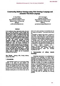
To illustrate the steps and activities involved in situated process design, we use the example of design optimisation. Optimisation can be described as a process that takes as its input a problem statement, including a set of object design parameters, required object performances and object constraints. Its output includes a set of values for the object design parameters, representing the best performing object design solution. The transformation is commonly viewed as encompassing the activities shown within the UML activity diagram in Figure 14. The loop in the diagram accounts for the iterative structure that is common in most optimisation processes.
Figure 14. Process structure of design optimisation
Each activity can be regarded as an individual process. For example, the activity “produce a mathematical model” is a sub-process of optimisation, which can again be viewed in terms of FBS. A distinctive function of this sub-process is to provide the necessary formalism for applying computational
operations
on
the
optimisation
problem.
Behaviours
include
performance
characteristics (such as accuracy and speed) that support the function of the sub-process within optimisation. Structure includes a sequence of activities as part of the transformation component, Figure 15.
Figure 15. Process structure of “produce a mathematical model”
The activities of this sub-process may be viewed in ever more detail, and multiple FBS models can be constructed and organised in a hierarchical structure. This is similar to object-centred views of the world, in which objects can be modelled as assemblies of other objects at multiple layers.
Carrying out an optimisation process can be viewed as the act of designing its structure. In the 21
situated FBS framework, this can be modelled as follows: 1. Formulation: This design step includes the interpretation of external requirements (FRe, BRe and SRe) and the generation of additional, “implicit” requirements (Fi, Bi and Si) via constructive memory. External requirements are often given to the designer in form of (or in conjunction with) the problem statement. For example, FRe may be stated “to support the conceptual stage in product development”, BRe may specify time constraints (i.e. required speed) on the optimisation process, and SRe includes the problem statement. The interpretation of these requirements is subjective to the individual designer. Implicit requirements may include implicit assumptions about resource efficiency (Fi) in terms of computational tools and human labour, cost considerations (Bi), and the process structure (Si) interpreted from Figure 14. Implicit requirements also include refinements of these concepts in form of FBS views of the sub-processes of optimisation, such as outlined for the sub-process “produce a mathematical model”. The construction of implicit requirements is heavily based on individual experience. The design state space of the optimisation process is formulated by focussing on the explicit and implicit process requirements, and by constructing additional expected behaviour (Bei) based on expected function (Fei). An example for the latter is the designer’s decision about the expected accuracy (Bei) of the optimisation process. Here, given that this process is “to support the conceptual stage in product development” (Fei), the designer may select a lower accuracy than would be needed if the optimisation was to support more detailed stages in product development. 2. Synthesis: This design step instantiates and externalises the structure of formulated processes and sub-processes. Take the overall structure shown in Figure 14, synthesis includes determining not only the final results, but also the specific object design variables and search methods, and the specific path on which the optimisation proceeds (e.g. if and how many times it iterates). 3. Analysis: This design step involves interpreting the structure of the processes that have been externalised through synthesis. What the outcomes of this activity are depends on the
22
experience and current goals of the designer. For example, the designer may choose to look closer at the output rather than the transformation of the optimisation, if accuracy is given priority over speed for evaluating process performance. 4. Evaluation: This design step compares the actual performance of optimisation against the expected performance. 5. Documentation: This design step externalises the representation of the final process design for purposes of communication. This includes the capture of process-centred design rationale for explaining why a particular optimisation method was chosen. 6. Reformulation type 1: This design step reformulates optimisation structure, which is usually done when performance is unsatisfactory. Common examples of reformulating optimisation structure are the elimination of object design variables and the modification of search methods. They are necessary in many non-linear optimisation problems where discontinuities in the search space produce difficulties for gradient-based search methods in finding the global optimum result. Figure 16 shows the example of a reformulated optimisation structure through modification of object design variables or search method. What exactly this modification produces depends on the individual experience of the designer, which is captured as interpretation and constructive memory in the situated FBS framework.
Figure 16. Reformulated process structure of a design optimisation process, through the addition of a new iteration
7. Reformulation type 2: This design step reformulates optimisation behaviour. This is frequently driven by new project constraints, represented as external requirements on behaviour (BRe). For example, the project manager may demand a faster pace of optimisation due to increased market competition. 8. Reformulation type 3: This design step reformulates optimisation function. Typically, this is driven by external requirements (FRe) that define a new role for the optimisation in the product
development process. For example, they may change the function “to support the detail design 23
stage”, which may then lead to changed expected behaviours such as increased accuracy.
5. Conclusion We have presented the FBS ontology as a structured conceptualisation of the domain of processes. We claim that any class of process can be represented using this ontology. A number of examples of processes in the design domain have been described in this paper demonstrating its coverage. Future work will focus on providing a more systematic evaluation of the ontology across different domains. Our ontology provides a uniform representation that allows locating as well as distinguishing between them. This enables comparison of different process models, even if they use differing terminologies or notations. Efforts towards unifying models of the design process (Grabowski et al. 1998) may benefit from this work. Integrating function and behaviour in a process ontology adds semantics to process representations, which accounts for their applicability in a purposive context. This is useful for knowledge representations of processes, as they can be deployed by a knowledge-based system to generate, compare and execute specific processes according to its current goals. Such knowledge representations are equivalent to Gero’s (1990) design prototypes based on the FBS ontology for design objects. The ability to support different views and purposes of processes at functional, behavioural and structural levels increases flexibility and applicability of the system in different situations. The situated FBS framework has been presented to model the steps and activities involved in the situated design of processes. There have been other approaches that use similar notions of function, behaviour and structure (Stroulia and Goel 1995; Murdock and Goel 2001); however, their focus is on modelling reflective reasoning architectures rather than on specifying a general process ontology. We can see the opportunity to deploy our FBS ontology within a reasoning mechanism, exploiting its ability to use the same fundamental constructs – function, behaviour and structure – as for objects. This allows developing design systems or agents that can flexibly reason about a variety of objects and processes
without having to implement different, specialised cognitive mechanisms. As everything in the world 24
looks the same when viewed in terms of FBS, only one cognitive mechanism is required.
Acknowledgements This research is supported by a grant from the Australian Research Council, grant number DP0559885.
References Bartlett, FC: 1932 reprinted in 1977, Remembering: A Study in Experimental and Social Psychology, Cambridge University Press, Cambridge. Bickhard, MH and Campbell, RL: 1996, Topologies of learning, New Ideas in Psychology 14(2): 111-156. Chandler, AD: 1962, Strategy and Structure, MIT Press, Cambridge. Chandrasekaran, B, Goel, AK and Iwasaki, Y: 1993, Functional representation as design rationale, IEEE Computer 26(1): 48-56. Chandrasekaran, B and Josephson, JR: 2000, Function in device representation, Engineering with Computers 16(3-4): 162177. Clancey, WJ: 1997, Situated Cognition: On Human Knowledge and Computer Representations, Cambridge University Press, Cambridge. Clibbon, K and Edmonds, E: 1996, Representing strategic design knowledge, Engineering Applications of Artificial Intelligence 9(4): 349-357. Cross, N: 1994, Engineering Design Methods: Strategies for Product Design, John Wiley & Sons, Chichester. Cummings, S and Wilson, D (eds): 2003, Images of Strategy, Blackwell Publishers, Oxford. de Kleer, J and Brown, JS: 1984, A qualitative physics based on confluences, Artificial Intelligence 24: 7-83. Dewey, J: 1896 reprinted in 1981, The reflex arc concept in psychology, Psychological Review 3, 357-370. Gero, JS: 1990, Design prototypes: A knowledge representation schema for design, AI Magazine 11(4): 26-36. Gero, JS: 1999, Constructive memory in design thinking, in G Goldschmidt and W Porter (eds), Design Thinking Research Symposium: Design Representation, MIT, Cambridge, MA, pp. 29-35. Gero, JS and Fujii, H: 2000, A computational framework for concept formation for a situated design agent, Knowledge-Based Systems 13(6): 361-368. Gero, JS and Kannengiesser, U: 2004, The situated function-behaviour-structure framework, Design Studies 25(4): 373-391. Grabowski, H, Rude, S and Grein, G (eds): 1998, Universal Design Theory, Shaker Verlag, Aachen. Gruber, TR: 1989, Automated knowledge acquisition for strategic knowledge, Machine Learning 4: 293-336.
Haymaker, J and Fischer, M: 2001, Challenges and benefits of 4D modeling on the Walt Disney concert hall project, CIFE Working Paper #64, Center for Integrated Facility Engineering, Stanford University, Stanford, CA.
25
Hori, K: 2000, An ontology of strategic knowledge: Key concepts and applications, Knowledge-Based Systems 13: 369-374. Hubka, V and Eder, WE: 1996, Design Science: Introduction to the Needs, Scope and Organization of Engineering Design Knowledge, Springer-Verlag, Berlin. IAI, 2006: Industry foundation classes IFC2x Edition 3, International Alliance for Interoperability, http://www.iaiinternational.org/Model/R2x3_final/index.htm. Kitamura, Y, Kashiwase, M, Fuse, M and Mizoguchi, R: 2004, Deployment of an ontological framework of functional design knowledge, Advanced Engineering Informatics 18(2): 115-127. Mintzberg, H and Waters, JA: 1985, Of strategies, deliberate and emergent, Strategic Management Journal 6(3): 257-272. Motus, L and Rodd, MG: 1994, Timing Analysis of Real-Time Software, Pergamon Press, Oxford. Murdock, JW and Goel, A: 2001, Meta-case-based reasoning: Using functional models to adapt case-based agents, in DW Aha and I Watson (eds) International Conference on Case-Based Reasoning 2001, Springer, Berlin, pp. 407-421. NIST: 1993, Integration definition for function modeling (IDEF0), Federal Information Processing Standards Publication 183, National Institute of Standards and Technology, Gaithersburg, MD. NIST: 2000, The process specification language (PSL): Overview and version 1.0 specification, NIST Internal Report 6459, National Institute of Standards and Technology, Gaithersburg, MD. NIST: 2004, Inputs and outputs in the process specification language, NIST Internal Report 7152, National Institute of Standards and Technology, Gaithersburg, MD. Schön, DA: 1983, The Reflective Practitioner: How Professionals Think in Action, Harper Collins, New York. Schön, DA and Wiggins, G: 1992, Kinds of seeing and their functions in designing, Design Studies 13(2): 135-156. Sim, SK and Duffy, AHB: 1998, A foundation for machine learning in design, Artificial Intelligence for Engineering Design, Analysis and Manufacturing 12(2): 193-209. Smith, GJ and Gero, JS: 2005, What does an artificial design agent mean by being ‘situated’?, Design Studies 26(5): 535561. Stone, RB and Wood, KL: 2000, Development of a functional basis for design, Journal of Mechanical Design 122(4): 359370. Stroulia, E and Goel, A: 1995, Functional representation and reasoning in reflective systems, Journal of Applied Intelligence 9(1): 101-124. Suwa, M, Gero, JS and Purcell, T: 1999, Unexpected discoveries and s-inventions of design requirements: A key to creative designs, in JS Gero and ML Maher (eds) Computational Models of Creative Design IV, Key Centre of Design Computing and Cognition, University of Sydney, Sydney, Australia, pp. 297-320.
von der Weth, R: 1999, Design instinct? – The development of individual strategies, Design Studies 20(5): 453-463.
26
Wiest, JD and Levy, FK: 1977, A Management Guide to PERT/CPM, Prentice-Hall, Englewood Cliffs. Ziemke, T: 1999, Rethinking grounding, in A Riegler, M Peschl and A von Stein (eds) Understanding Representation in the Cognitive Sciences: Does Representation Need Reality?, Plenum Press, New York, pp. 177-190.
Author Biographies
27
John S. Gero is Research Professor at the Krasnow Institute for Advanced Study and the Department of Computer Science, George Mason University and Visiting Professor at the Massachusetts Institute of Technology. Formerly he was the Professor of Design Science and CoDirector of the Key Centre of Design Computing at the University of Sydney. He is the author/editor of 43 books and has published over 550 research papers. He has been a visiting professor of architecture, civil engineering. cognitive psychology, computer science, design and computation, and mechanical engineering in the USA, UK, France and Switzerland. His research focuses on computational, cognitive and neurocognitive studies of designing.
Udo Kannengiesser is a researcher in the Empirical Software Engineering program at NICTA, an Australian research institute in information and communication technology. He recently obtained his PhD at the Key Centre of Design Computing and Cognition at the University of Sydney. He holds a degree in mechanical engineering from the University of Karlsruhe, Germany, with a specialisation in information systems for design and production.
28
Figure 1. The structure of a process. (i = input; t = transformation; o = output)
Figure 2. Situatedness as the interaction of three worlds: (a) general model, (b) specialised model for design representations (after Gero and Kannengiesser (2004)).
29
Figure 3. External and interpreted FBS representations of processes.
Figure 4. External, interpreted and expected FBS representations of processes.
30
9.
Figure 5. The situated FBS framework (after Gero and Kannengiesser (2004)
Figure 6. Formulation
10.
31
Figure 7. Synthesis
11.
Figure 8. Analysis
Figure 9. Evaluation
32
Figure 10. Documentation
Figure 11. Reformulation type 1, in black (the activities representing potential drivers for this design step are depicted as grey symbols)
Figure 12. Reformulation type 2, in black (the activities representing potential drivers for this design step are depicted as grey symbols)
33
Figure 13. Reformulation type 3, in black (the activities representing potential drivers for this design step are depicted as grey symbols)
Figure 14. Process structure of design optimisation
Figure 15. Process structure of “produce a mathematical model”
34
9.
Figure 16. Reformulated process structure of a design optimisation process, through the addition of a new iteration