Demo Abstract: A Funneling-MAC for High Performance Data Collection in Sensor Networks Gahng-Seop Ahn
Emiliano Miluzzo
Andrew T. Campbell
Electrical Engineering Dept. Columbia University New York, NY
[email protected]
Computer Science Dept. Dartmouth College Hanover, NH
[email protected]
Computer Science Dept. Dartmouth College Hanover, NH
[email protected]
Categories and Subject Descriptors C.2.1 [Computer-Communications Networks]: Network Architecture and Design --- Wireless Communications
General Terms Protocol, Algorithm, Design, Implementation
Keywords Wireless Sensor Networks, Medium Access Control Protocol
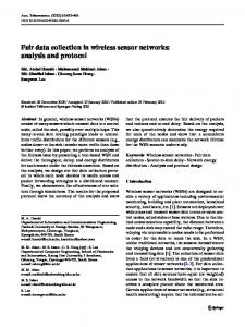
1. INTRODUCTION In this demonstration, we show the implementation, deployment, and evaluation of the funneling-MAC [1], a new high-performance media access controller for sensor networks. The funneling-MAC provides a simple set of algorithms that boost the performance of data collection in comparison to existing TinyOS deployed MACs, such as, B-MAC [3] and Z-MAC [4]. The funneling-MAC source code is freely available from the web [5] for experimentation. In what follows, we discuss the ideas behind the new MAC and its implementation and demonstration. We first discuss the problem that the new MAC addresses. Wireless sensor networks exhibit a unique funneling effect [2] where events generated in the sensor field travel hop-by-hop in a many-to-one traffic pattern toward one or more sink points, as illustrated in Figure 1. This traffic pattern creates a choke point resulting in a significant increase in transit traffic intensity, collision, congestion, packet loss, and energy drain as events move closer toward the sink. While network (e.g., congestion control) and application techniques (e.g., aggregation) can help counter this problem they cannot fully alleviate it. We take a different but complementary approach to solve this problem than found in the literature and propose a funneling-MAC [1] capable of mitigating the funneling effect and boosting application fidelity in sensor networks. The funneling-MAC is based on a CSMA/CA being implemented network-wide, with a localized TDMA algorithm overlaid in the funneling region (i.e., within a small number of hops from the sink). In this sense, the funneling-MAC represents a hybrid MAC approach but does not have the scalability problems associated with the network-wide deployment of TDMA. The funneling-MAC is 'sink-oriented' because the burden of managing the This work is supported by the Army Research Office (ARO) under Award W911NF-04-1-0311 on resilient sensor networks. Copyright is held by the author/owner(s). SenSys'06, November 1-3, 2006, Boulder, Colorado, USA. ACM 1-59593-343-3/06/0011.
TDMA scheduling of sensor events in the funneling region falls on the sink node, and not on resource limited sensor nodes; and it is 'localized' because TDMA only operates locally in the funneling region close to the sink and not across the complete sensor field. We implemented the funneling-MAC on MICA-2 motes and TinyOS platform. We have shown in [1] that the funneling-MAC mitigates the funneling effect, improves throughput, loss, and energy efficiency, and importantly, significantly outperforms other representative protocols such as B-MAC [3], and more recent hybrid TDMA/CSMA MAC protocols such as Z-MAC [4]. In what follows, we provide a brief overview of the implementation of the funneling-MAC algorithms and then discuss the demonstration.
2. FUNNELING-MAC The funneling-MAC [1] localized TDMA is triggered by a beacon broadcast by the sink. All sensor nodes perform CSMA by default unless they receive a beacon. The sink regulates the boundary of the intensity area (see Figure 2) by controlling the transmission power of the beacon. Dynamic depth-tuning algorithm determines this transmission power based on the traffic load of the sensor network. The sink then transmits the beacon message at the computed transmission power. The nodes that received the beacon consider themselves to be in the intensity region (and designate themselves as f-nodes). These f-nodes perform TDMA while the nodes that do not receive the beacon (i.e., those nodes outside the intensity region) perform CSMA, as shown in Figure 2. The beacon is also used to synchronize f-nodes. As soon as f-nodes receive a beacon, they synchronize with other f-nodes by initializing their clocks. In essence, scheduling (TDMA) operates in the first few hops (i.e., the intensity region) of the sink where sensors
funnel
pure CSMA hybrid TDMA/CSMA
intensity region
choke point sink
Figure 1: Funneling effect in sensor networks
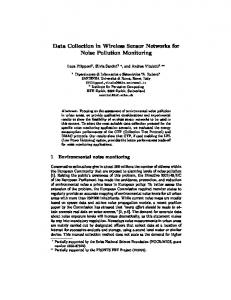
3. WHAT WILL BE DEMONSTRATED? 3.1 Testbed Setup We demonstrate a dense 45 node multi-hop wireless network using MICA-2 motes running TinyOS, as illustrated in Figure 2. We implement the funneling-MAC on B-MAC [3], which provides the baseline CSMA/CA system. We use the default TinyOS MintRoute routing protocol and Surge application to drive various source rates in the demonstration. We use a laptop as a server that manages the sensor network, controls the sink, and displays the performance of the sensor network. One of the MICA-2 nodes is used as a sink. The sink is mounted on MIB-600 programming board that is wired to the laptop server. We place 44 motes on a reasonably sized table for demo purposes, representing a dense table-top sensor field. The transmission radii of motes are configured so that multi-hop wireless network can be deployed on the demonstration table.
3.2 Demo Content We randomly select 16 of the 44 sensing nodes to generate events that are periodically reported to the sink with rates ranging from 0.2-6 packets/sec (pps) where the packet size is 36 bytes. The goal is to gradually drive the sensor network from low to moderate load and then into a congested and saturated state, while demonstrating how the funneling-MAC operates to mitigate the funneling effect. We will also demonstrate the impact of the funneling effect using B-MAC. Typically, events travel over multiple hops, 2-5 hops in the case of the experiment. We use the TinyOS SerialForwarder and Oscilloscope to demonstrate: i) the throughput of the sensor network, ii) the boundary of the intensity region, iii) the TDMA schedule.
Y-Coordination
80-90% of loss occurs, as shown in [1]. Outside of this region only standard CSMA runs. The sink monitors the traffic that arrives at the sink and calculates the TDMA schedule based on the monitored traffic (initially based on only new CSMA events and thereafter including existing TDMA traffic) for all aggregated-paths [1], and distributes the schedule by broadcasting a schedule packet at the same transmission power used by beaconing. Once f-nodes receive a schedule, they transmit packets at their allocated slots in the TDMA frame [1]. To enhance the robustness and flexibility of the funneling-MAC, a CSMA frame (random access period) is reserved between two consecutive TDMA frame (scheduled access period) schedules, and carrier sensing is performed even for scheduled transmissions. All f-nodes that received a new beacon and schedule from the sink, embed a meta-schedule in the first data packet transmitted toward the sink after receiving a beacon. Nodes that are either inside the intensity region and miss a beacon or outside the intensity region but near the boundary can overhear the transmission of metaschedule carried in a data event. Reception of the metaschedule allows these nodes to transmit in the CSMA portion of the current superframe [1] mitigating the likelihood of interfering.
4
sensors
3 2 1
beacon 0
sink
0
1
2
f-nodes
3
4
boundary of the intensity region
5
6
7
8
X-Coordinat ion
Figure 2. Grid sensor testbed First, we illustrate the throughput as the number of packets that are delivered from these source sensors to the sink per second. Second, we show how the boundary of the intensity region is determined and regulated. The funneling-MAC uses beacons to regulate the boundary of the intensity region. The boundary can change each time a beacon is sent by the sink. We show using the Oscilloscope the number of times each node finds itself in the intensity region. Then, we demonstrate how the schedule is calculated by illustrating the number of slots each node is assigned. We demonstrate how beaconing and the dynamic depth-tuning algorithm of the funnelingMAC protocol operate using the LEDs on the MICA-2 motes. When the sink transmits a beacon, one of the LEDs on the sink blinks to indicate that the beacon is sent. If a sensor node recognizes itself as a member of the intensity region, one of the LEDs on the sensor node blinks too. By observing the blinking LEDs on the sensor field, we can visually recognize the boundary of the intensity region. To demonstrate how dynamic depth tuning works, we tune the periodic reporting rate of the source sensors on-the-fly. The sink computes the optimal depth related to the measured traffic pattern and sends the next beacon accordingly. The membership of the intensity region is changed by reception of a new beacon, and nodes may blink LEDs accordingly. We can observe how the boundary of the intensity region changes as the traffic load in the sensor field changes.
4. REFERENCES [1] G.-S. Ahn, E. Miluzzo, A. T. Campbell, S. G. Hong and
F. Cuomo, “Funneling-MAC: A Localized, SinkOriented MAC for Boosting Fidelity in Sensor Networks”, ACM Sensys 2006, November 2006. [2] C.-Y. Wan, S. E. Eisenman, A. T. Campbell, and J.
Crowcroft, “Siphon: Overload Traffic Management using Multi-Radio Virtual Sinks”, ACM SenSys 2005, San Diego, November 2005. [3] J. Polastre, et al., “Versatile Low Power Media Access
for Wireless Sensor Networks”, ACM SenSys 2004, Baltimore, November 2004. [4] I. Rhee, et al., “ZMAC: a Hybrid MAC for Wireless
Sensor Networks”, ACM SenSys 2005, November 2005. [5] Funneling-MAC project webpage:
http://www.cs.dartmouth.edu/ ~sensorlab/funneling-mac