A Fuzzy Flight Controller Combining Linguistic and Model-Based Fuzzy Control B. Kadmiry∗ Dept. of Computer Sci. (AIICS) Link¨oping University
[email protected]
D. Driankov Dept. of Technology (AASS) ¨ Orebro University
[email protected]
Abstract In this paper we address the design of a fuzzy flight controller that achieves stable and robust “aggressive” manoeuvrability for an unmanned helicopter. The fuzzy flight controller proposed consists of a combination of a fuzzy gain scheduler and linguistic (Mamdani-type) controller. The fuzzy gain scheduler is used for stable and robust altitude, roll, pitch, and yaw control. The linguistic controller is used to compute the inputs to the fuzzy gain scheduler, i.e., desired values for roll, pitch, and yaw at given desired altitude and horizontal velocities. The flight controller is obtained and tested in simulation using a realistic nonlinear MIMO model of a real unmanned helicopter platform, the APID-MK3.
Keywords: unmanned helicopter, Takagi-Sugeno fuzzy control, fuzzy gain scheduling, linguistic modelling and control.
1 Introduction The central problem addressed in this paper is the design of a flight controller that achieves stable and robust “aggressive” manoeuvrability for an unmanned helicopter. Thus, the flight controller described here executes, in a stable and robust manner: i) tracking of trajectories describing curvilinear translational (or horizontal) motion at relatively high speed, and ii) set-point regulation for fast acceleration/deceleration, hovering and climb. The robustness of the flight controller is defined as its ability to compensate for: i) external disturbances in terms of wind gusts, ii) model parameter uncertainties in terms of changing payload, and iii) sensor noise for attitude control signals. While almost all existing work in this area uses various modifications of feedback linearization we employ a gain-scheduling approach based on the use of Takagi-Sugeno fuzzy models [1], i.e., fuzzy gain-scheduling. This provides for a simultaneous synthesis of linear controllers and a gain scheduler with guaranteed global stability and robustness properties. The flight controller presented here is obtained and tested in simulation using a realistic nonlinear MIMO model of a real unmanned helicopter platform, the APID-MK3. We are completely aware that the “realism” of the results reported in this work w.r.t. the above aims is limited by the fact that all the work is performed in simulation. However, since the mathematical model used for simulation is close enough, from control point of view, to the real APID-MK3 system we have all reasons to believe in the realism of these results. The paper is organized as follows. Section 2 provides the motivation for the work presented in this paper by discussing the need for aggressive manoeuvrability and the use of fuzzy gain scheduling. Section 3 describes related work on the control of unmanned helicopters so that a proper framework is provided within which the contributions of our work can be evaluated. Section 4 presents the overall cascaded control scheme for the flight controller and defines the control tasks to be executed by its inner- and outer-loop controllers. Section 5 introduces fuzzy gain-scheduled (FGS) controller design and Section 6 the so-called Mamdani fuzzy controllers. Section 7 presents the design of the inner- and outer-loop controllers respectively: the outer-loop uses Mamdani controllers to determine desired attitude angles that can achieve desired velocity at a given altitude. Then the inner-loop takes these desired attitude angles as inputs and generates the actuator deflections ∗ Address
of corresponding author: Bourhane Kadmiry, Link¨oping University, Dept. of Computer and Information Science (AIICS), F490. SE-581 83 Link¨oping, Sweden. tel: (+46) 13 284493; fax: (+46) 13 285868.
1
that will result in that attitude. Section 8 presents the result of simulations showing that the objective of aggressive, and robust manoeuvrability has been achieved. In Section 9 we provide the reader with some conclusions.
2 Motivation 2.1 Why aggressive manoeuvrability ? The work reported in this paper is a contribution to the overall objective of the Wallenberg Laboratory for Information Technology and Autonomous Systems (WITAS, www.ida.liu.se/ext/witas) at Link¨oping University: the development of an intelligent, deliberative/reactive command and control system, containing active-vision sensors, which supports the operation of a unmanned air vehicle (UAV) in both semi- and full-autonomy modes. One of the UAV platforms of choice is the APID MK3 unmanned helicopter. The present version of APID MK3 is capable of unmanned take-off, landing, hovering, and motion along linear trajectories with a constant low-speed. This is enough for performing missions like site mapping and surveillance, and electronic warfare and communications where the predominant flight modes used are hovering at predefined points and slowly moving, along a predefined straight-line, from one hovering point to another. Other type of missions, e.g., tracking a ground vehicle, require the execution of curvilinear trajectories with a varying speed profile. However, the current control system for APID MK3 does not utilize large ranges of the rotor attitude angles. As a consequence this produces lower rate-of-change of the body attitude angles. Consequently, the control is done on rather small ranges for these and this restricts the magnitude of the curvature of the trajectory which these angles can follow at a given relatively high speed. Furthermore, control within small ranges for the body attitude angles implies small acceleration rate – a shortcoming when a ground object is capable of accelerating at higher rates. Last but not least, the ability to decelerate fast is necessary for safe navigation when sudden unknown terrain elevations are encountered and have to be avoided as fast as possible. In this context, the objective of achieving “aggressive” manoeuvrability concerns the design of an attitude controller which acts on much larger ranges of the body attitude angles, i.e., −π/4 ≤ φ ≤ +π/4, −π/4 ≤ θ ≤ +π/4, −π ≤ ψ ≤ +π, by utilizing the full range of the rotor attitude angles. The latter are approximated to the interval [−0.25, +0.25] rad. The controller should achieve robust and stable tracking of trajectories with varying curvature magnitude at relatively high speed. It has to be noted here that the above interpretation of “aggressive manoeuvrability” agrees with the one given in [2], that is “ the ability to track fast trajectories”. A principally different reading of “aggressive manoeuvrability” is provided in [3] in: “the finite time transition between two trim trajectories”. Trim trajectories are defined as those trajectories along which the velocities in body axes (the twist) and the control input are constant.
2.2 Why fuzzy gain scheduling ? A study of the relevant literature on unmanned helicopter control reveals very few well-documented case when a nonlinear model of an unmanned helicopter is deployed for the controller design. In all other cases the design is based on linear models and the linear control techniques used are µ-synthesis [4], H∞ [5], or Linear Quadratic Gaussian LQG [6]. Examples include: i) Linear robust controller implemented on the Yamaha R-50 at Carnegie Mellon University. The controller consists of one MIMO loop for attitude stabilization and four separate SISO loops for velocity and position control and the speed of motion achieved is 4 m/s; ii) MIMO linear controller, based on µ-synthesis, is implemented on the Yamaha R-50 at the University of California at Berkeley for control during hover and way-point navigation. Recent flight test at speeds up to 6m/s were reported; iii) MIMO H∞ and LQG hovering controllers [7] are implemented on the Caltech’s Kyosho EP Concept electric model helicopter. It is important to emphasize on the fact that all linear designs are implemented and tested on the real platforms, while almost all nonlinear designs only are evaluated in simulation with the exception of the Georgia Tech controller implemented on the Yamaha-50 platform. The predominant nonlinear controller designs are based on the notion of feedback linearization [8] of the original nonlinear helicopter model. The idea here is to transform the nonlinear dynamics into a linear form by using state feedback, with input-state linearization corresponding to complete linearization, and input-output linearization to partial linearization. It is
2
the latter type of feedback linearization that is normally used for controller design in the case of unmanned helicopters. Input-output linearization means the generation of a linear differential relation between the output and a new input. By means of this the dynamics of the original nonlinear system is decomposed into external (input-output) part and internal (unobservable) part. Since the external part consists of a linear relation between the output and the new input it is easy to design the input so that the output behaves as desired. Then the question is whether the internal part will also behave well, i.e., whether the internal states will remain bounded. The answer to this question is provided by studying the so-called zerodynamics of the internal part, i.e., the dynamics when the control input is such that the output is maintained at zero. If an input-output linearized system has stable zero dynamics it is called minimum phase, and if it has unstable dynamics then it is a non-minimum phase. The control law for a minimum phase system can simply be obtained by model inversion. However this type of control law cannot be applied to non-minimum phase systems since they are not invertible. Thus the major focus in all reported controller designs for unmanned helicopters that are based on input-output linearization is: the generation of such input-output relation for the original nonlinear system so that the internal dynamics of the input-output linearized system is either minimum phase or it has no internal (zero-) dynamics. An input-output linearized system with no internal dynamics can be obtained as follows [9]: when performing successive differentiations of the selected output, to simply neglect the terms containing the input and keep differentiating the output a number of times equal to the system’s order, so that there is “approximately” no internal dynamics. Of course this approach is only meaningful if the input coefficients at the intermediate steps are “small”, i.e., the system is “weakly non-minimum phase”, i.e., “fast ” right-half plane zeros are neglected. Controller designs based on input-output linearization have a number of important limitations amongst which the most important one, in the context of control of unmanned helicopters, is that no robustness is guaranteed in the presence of parameter uncertainties, unmodelled dynamics, or external disturbances [8]. In this context, the dynamic output fuzzy gainscheduling controller [10] designed within the H∞ framework and presented in this thesis allows to: 1) shape the closed loop transient dynamics so that it conforms to performance specifications; and 2) design a robust controller that rejects the influence of bounded model uncertainties and external disturbances. Yet another principal difference between fuzzy gainscheduling and input-output linearization is that: fuzzy gain-scheduling design is a technique for transforming the original nonlinear system into another nonlinear system while input-output linearization transforms the original nonlinear system into a (fully or partially) linear system.
3 Related work In recent years, the design and implementation of control algorithms for unmanned helicopters has been the object of quite a number of studies. In order to provide a proper framework within which the contributions of this thesis can be meaningfully evaluated we will only consider here studies that report in significant level of detail control algorithms that make use of nonlinear models and their performance is evaluated either on the real platform or in simulation of a mathematical model close enough to the real platform.
3.1 The Berkeley Aerorobot Team The controller design [11] is based on a nonlinear model of the Ursa-Minor unmanned helicopter and its performance has so far been evaluated in simulation. In particular, the design is based on approximate input-output linearization of the original nonlinear helicopter model. “Approximate” here means that the input-output linearization is performed on the original nonlinear model only after the coupling effect between rolling moment and lateral force on one side and pitching moment and longitudinal force on the other are neglected. Then by choosing positions and heading as outputs and applying a dynamic decoupling algorithm [12] a linearized helicopter model which does not contain any unobservable zero-dynamics, and hence is minimum phase, is obtained. Finally, a tracking control law for this linearized model is designed and applied to the original nonlinear helicopter model so that a bounded tracking error is guaranteed. However, as noticed in [13], the so-obtained tracking control law is sensitive to model disparities such as changes in the payload or the thrust-torque model, or external disturbances such as side-winds. Though, as mentioned in [10], the tracking error can be reduced by placing the poles further away from the origin in the left-half plane, this comes with a price – higher control input magnitude which may not be physically feasible. As already mentioned, this type of robustness limitations is inherent to all controller designs based on input-output linearization. 3
3.2 The Georgia Tech Aerial Robotics Mission The design of an attitude controller is done on approximate linear model of the rotational dynamics and implemented on the Yamaha R-50 unmanned helicopter (see www.ae.gatech.edu/research/controls /labs/uavrf/). The controller design [14] uses linear model inversion. However, since the linear model is only approximation of the real dynamics of the helicopter it is subject to modelling errors arising from flight conditions and inaccurate modelling. Hence, an adaptive unit in the form of a neural network, is used to cancel the inversion errors using feedback and a stable update law based on Lyapunov stability theory. This same structure is used in all three channels, roll, pitch, and yaw. The adaptive unit also adjusts to changing atmospheric conditions and dynamics. Thus, the controller can be used at different points in the flight envelope without tuning.
3.3 The Fuzzy Unmanned Helicopter The work by Sugeno [15] reports a hierarchical, Mamdani-type of a controller for the unmanned helicopter Yamaha R-50 by Yamaha Motors. The lower layer contains a number of Mamdani-type control modules: longitudinal (pitch control), lateral (roll control), collective (vertical control), rudder (yaw control), and coupling compensation modules. Furthermore, within each such module there is a number of sub-modules only some of which correspond directly to our Mamdani-type controller from Sect. 7.3 These are as follows: • Longitudinal: this module includes a x˙ Mamdani-type controller. The x˙ controller infers a desired pitch angle using a velocity-error and its derivative and is identical to the one used by us; • Lateral: this module includes a y˙ Mamdani-type controller. The y˙ controller infers a desired roll angle using a velocity-error and its derivative and is identical to the one used by us; • Collective: this module includes a z˙ Mamdani-type controller. The z˙ controller infers a control value for the main collective using altitude, velocity-error and its derivative; • Rudder: this module, given a desired heading, infers a control input for the tail collective using yaw angle error and its rate of change; • Coupling compensation: the use of this module is twofold: i) it takes into account cross-couplings between longitudinal/lateral and vertical motion; ii) it takes into account cross-couplings between yaw and roll during a turn. In Section 7.4, we make a detailed comparison between our outer-loop Mamdani-type controller and the one proposed by Sugeno, and point out important differences.
4 The control scheme Having in mind that VTOL vehicles of any kind are maneuvered by controlling their attitude angles, i.e., roll, pitch, and yaw, it is only natural to design the flight controller as consisting of two cascaded controllers: a translational controller and an attitude controller. This cascaded structure implies two control loops: • the inner loop, that has the fastest dynamics, is the attitude controller. It takes desired attitude angles as inputs and generates the actuator commands that will result in the desired attitude; • the outer-loop controls the slower translational rate variables. It takes desired velocity/position as input and generates desired attitude angles that will produce the desired velocity/position. The above scheme for the overall flight controller is presented in Fig. 1 and it has to be mentioned here that it is common for all flight controller designs considered in the introductory chapter. However, we differ somewhat from this general control scheme. In the case of the Mamdani plus FGS controller design, the inputs to the inner-loop are not only desired attitude angles but also a desired altitude, see Fig. 2. This leads to the fact that in this case we do not have a pure attitude controller but, an altitude-and-attitude controller. 4
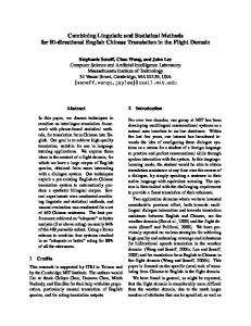
Figure 1: Overall flight control scheme
Fig. 1 presents the overall flight control scheme, where, V d or P d stand for desired velocity or position respectively, that is V d = (Vx , Vy , Vz )d or P d = (x, y, z)d . The outer-loop regulates these reference values and outputs desired attitude angles. The inner-loop control is designed to regulate desired values of the attitude angles (φ, θ, ψ)d and feeds the model with control inputs for the cyclic angles (φc , θc ) and collective angles (θM , θT ) to control the main and tail rotors respectively. Fig. 2 presents Mamdani plus FGS controllers which inputs are desired horizontal velocity V d = (Vx , Vy )d and the desired
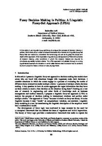
Figure 2: Control scheme for the fuzzy gain scheduling method heading χd . The Mamdani controller computes the desired attitude angles (φ, θ, ψ)d . These values –plus a desired altitude– are fed to the FGS controller which outputs the values for the control of the model in term of cyclic (φc , θc )and collective angles (θM , θT ) for the main and tail rotors respectively. One important reason for having altitude-and-attitude controller is as follows. The vertical motion of the helicopter depends on the relation between its weight and the lift force generated by the main rotor blades. If the lift force is greater than the weight, the helicopter accelerates upwards (climb); if it is less than the weight, the helicopter accelerates downwards (descent); and if it is equal to the weight, the helicopter remains at a constant altitude (hover). The horizontal motion of the helicopter (longitudinal – along the x-axis; and lateral – along the y-axis) occurs when there is a horizontal force component. Such a force is generated by inclining the lift force in the desired direction, inducing by that the trust force. However, because of the coupling between the different types of motion, the following effect is observed: when the lift force is inclined, creating a horizontal motion (trust/drag), the magnitude of the vertical component is decreased under the action of the weight, thus, causing loss of altitude. That is why we would like to control the attitude angles in such a way that a desired horizontal motion is produced but, without loss of altitude. This obviously can be achieved by a controller that is able to simultaneously regulate both the attitude angles and the altitude.
5 An introduction to fuzzy gain scheduling During the past decade two principally different approaches to the design of fuzzy controllers have emerged: heuristicsbased (or linguistic) and model-based designs.The latter are known under the name of Takagi-Sugeno (TS) fuzzy models and controllers or fuzzy gain schedulers. In our case, the linguistic design is applied to the outer-control loop of the flight controller. Since a set of well-known heuristics describing the relationship between horizontal velocities and attitude angles is readily available, these heuristics can be translated into a set of fuzzy if-then fuzzy rules of the Mamdani-type. The main applications of the model-based design are in cases when there is an available open-loop plant model, normally a nonlinear one of the MIMO type. The attitude-and-altitude dynamics of a helicopter are a typical example of such a nonlinear MIMO plant. However, there is no general method for designing nonlinear controllers. What is available today, is a collection of alternative and complementary techniques, each best applicable to a particular class of nonlinear systems. 5
This explains why the helicopter’s original nonlinear model has to be “modified” in one way or another in order a particular design technique to be used. In this context, the advantage of using Takagi-Sugeno models is that a large class of nonlinear plants, including the attitude dynamics of a helicopter, can be well represented by these models, without the need to modify the original nonlinear dynamics in any significant way.
5.1 Structure of the Takagi-Sugeno model The TS fuzzy model, originally proposed in [1], is composed of a fuzzy if-then rule base that partitions a space – usually called the universe of discourse – into fuzzy regions described by the rule antecedents. The consequent of each rule i is usually a functional expression yi = fi (x). A common format of a rule i is as follows: Rule i : IF θ1 is F1i AND θ2 is F2i AND . . . AND θq is Fqi THEN yi = fi (x). The vector θ ∈ Rq contains the premise variables and may be a subset of the independent variables x ∈ Rn . Each premise variable θj has its own universe of discourse that is partitioned into fuzzy regions by the fuzzy sets describing the linguistic variable Fjk . The premise variable θj belongs to a fuzzy set k with a truth value given by the membership function µjk (θj ) : R → [0, 1] for k = 1, 2, . . . , sj where sj is the number of fuzzy sets for premise variable j. The notation Fji and µij refers to the specific linguistic variable and its membership function respectively that correspond to the premise variable θj in rule i. That is, Fji ∈ {Fj1 , Fj2 , . . . , Fjsj } and µij (θj ) ∈ {µj1 (θj ), µj2 (θj ), . . . , µjsj (θj )}. The truth value (or activation degree) hi for the complete rule i is computed using the aggregation operator AND, also called a t-norm, which is often denoted by ⊗ : [0, 1] × [0, 1] → [0, 1], hi (θ) = µi1 (θ1 ) ⊗ µi2 (θ2 ) ⊗ . . . ⊗ µiq (θq ).
(1)
There is a number of different t-norms available, see [16]. However, in this work we will use the simple algebraic product, thus Eq.(1) reads q Y µij (θj ). (2) hi (θ) = j=1
The degree of activation for rule i is then normalized as wi (θ) = Pl
hi (θ)
r=1
hr (θ)
,
(3)
where l is the number of rules. This normalization implies that l X
wi (θ) = 1.
(4)
i=1
In conclusion, the response of the TS model, for a given x and θ, is a weighted sum of the consequent functions, fi , which reads l X y= wi (θ)fi (x). (5) i=1
Note that y in Eq.(5) is a convex combination of the local functions (models) fi , a fact that facilitates stability analysis.
5.2 TS models for dynamical systems This section presents the TS model described in Section 5.1 in the context of dynamical systems. A general continuous dynamical system may be given as x˙ = f (x, u, ϑ) y = g(x, u, ϑ), 6
(6)
where f : Rn × Rm × Rs → Rn and g : Rn × Rm × Rs → Rp . ϑ ∈ Rs is a vector of possibly time varying parameters. The functions f and g may very well be represented by a TS fuzzy system. Letting θ be a subset of x, u and ϑ we can write rule i in a fuzzy rule base as Rule i :IF θ1 is F1i AND θ2 is F2i AND . . . AND θq is Fqi ½ x˙ = fˆi (x, u, ϑ) THEN , y = gˆi (x, u, ϑ) where fˆi : Rn × Rm × Rs → Rn and gˆi : Rn × Rm × Rs → Rp . The TS fuzzy system is then written x˙ =
l X
wi (θ)fˆi (x, u, ϑ)
i=1
y=
l X
(7) wi (θ)ˆ gi (x, u, ϑ),
i=1
and the weights wi (θ) are computed as described in Eq.(3). The choice of the consequent functions fˆi and gˆi depends on the application. We will confine ourselves to the following case:
x˙ =
l X
wi (θ)(Ai x + Bi u) = A(θ)x + B(θ)u
i=1
y=
l X
(8) wi (θ)Ci x = C(θ)x,
i=1
or the more general form, derived from the Taylor expansion x˙ =
l X
wi (θ)(Ai x + Bi u + ai ) = A(θ)x + B(θ)u + a(θ)
i=1
y=
l X
(9) wi (θ)(Ci x + ci ) = C(θ)x + c(θ),
i=1
where Ai ∈ Rn×n , Bi ∈ Rn×m , ai ∈ Rn , Ci ∈ Rp×n and ci ∈ Rp . If it is not clear from the context, we will in the following label Eq.(8) as a homogeneous TS fuzzy system while we denote Eq.(9) as an affine TS fuzzy system.
5.3 Obtaining TS fuzzy models There are basically two principal ways to obtain a TS fuzzy model: nonlinear identification from experimental data or using linearization of some kind. A good exposure of different methods for TS fuzzy model identification is given in the collection [17]. A comprehensive description of a method for automatic identification of TS models for control purposes is also presented in [18]. The purpose of this section is to discuss how a TS fuzzy model of the form Eq.(8) or Eq.(9) can be obtained from the general nonlinear system description in Eq.(6). Thus, a nonlinear system is already given and we will not deal with identification, and thereby redirecting interested readers to the references mentioned above. It has been shown that a TS model of type Eq.(8) can approximate any smooth nonlinear function and its first order derivative [19]. Furthermore, in [20] it is shown that an affine TS system may also be able to approximate the second order derivatives of a smooth nonlinear function. Although the universal approximation capabilities are of a considerable theoretical interest we will only confine ourselves with the mechanism of how to approximate a nonlinear function by a TS model in this section. Two approaches are presented: the first one is based on approximation, using Taylor expansion of the nonlinear function in a number of points. The second one tries to find a linearizing transformation such that the nonlinear function is exactly represented by the fuzzy system over a specified domain. The two techniques have one thing in common: they strive to capture the nonlinearity of the original nonlinear system into the rule base. 7
5.3.1 Approximation by Taylor expansion The idea of this method is to do a first-order Taylor expansion in different points θi and let the rule base describe the validity of the obtained linear model in each point. First, one has to decide which variables in x, u and ϑ, i.e., the premise variables θ, capture the nonlinearities in Eq. (6). A reasonable number of linearization points together with a partition of the universe of discourse must also be chosen. The consequent system parameters are then obtained by ¯ ¯ ¯ ¯ ¯ ¯ ∂f ∂f ∂g ¯ ¯ Ai = (x, u, ϑ)¯ , Bi = (x, u, ϑ)¯ , Ci = (x, u, ϑ)¯¯ (10) ∂x ∂u ∂x xi ,ui ,ϑi xi ,ui ,ϑi xi ,ui ,ϑi with the affine terms ai = f (xi , ui , ϑi ) − Ai xi − Bi ui
(11)
ci = g(xi , ui , ϑi ) − Ci xi .
(12)
and Obviously, a TS model obtained by this method is an extension of a linear system obtained through linearization in an equilibrium point. As a parallel, in classical gain scheduling one does often approximate a nonlinear system with a number of linear systems obtained through linearization over the equilibrium manifold ε of the nonlinear system in Eq.(6), as ε = {(x, u, ϑ) | f (x, u, ϑ) = 0}.
(13)
See [21] for a discussion about linearization and classical gain scheduling. When linearizing outside the equilibrium manifold we obtain an affine term as in Eq.(9), see also the discussion in [22] and [23]. This implies that our approximation may resemble the original nonlinear system even outside the equilibrium manifold. We may also say that the fuzzy system approximates the flow of the vector field represented by Eq.(6) as discussed in [22]. 5.3.2 Approximation by a linearizing transformation Here we describe how a TS fuzzy model (without affine terms) may be represented by using sector bounded nonlinearities. This approach is thoroughly described in [24] and [25] and only an outline is given here. This technique can at least be used for continuously differentiable systems with f (0, 0) = 0. The idea is to bound nonlinearities by sectors described by linear subsystems. The resulting system is then written as a convex combination of these subsystem by transforming the original nonlinearities into fuzzy membership functions. Example 1 Consider the function f (x) = sin(x). We would like to express this function as a convex combination of linear functionals as follows µ1 (x)a1 x + (1 − µ1 (x))a2 x = sin(x) (14) with µ1 (x) ≥ 0 and µ1 (x) + (1 − µ1 (x)) = 1. Solving for µ1 (x) gives ½ sin(x)−a2 x x 6= 0 a1 x−a2 x µ1 (x) = 0 x=0
(15)
If we let x ∈ [xmin , xmax ] = [−π, π] we set a1 = minx sin(x) = −1 and a2 = maxx sin(x) = 1. Hence Eq.(15) becomes ½ x−sin(x) x 6= 0 2x µ1 (x) = (16) 0 x=0 Inserting Eq.(16) in to Eq.(14) we obtain equality for all x ∈ [xmin , xmax ]. Hence, it is possible to exactly represent sin(x) over an interval using a convex combination with the weights w1 (x) = µ1 (x) and w2 (x) = 1 − µ1 (x). The reasoning used in this example is easily extended to a wide variety of nonlinear functions and in particular to nonlinear systems of the form a11 (x, u) a12 (x, u) . . . a1n (x, u) x1 b11 (x, u) b12 (x, u) . . . b1m (x, u) u1 . . . . . . . . . . .. .. .. .. .. .. .. .. f (x, u) = .. + .. (17) an1 (x, u) an2 (x, u) . . .
ann (x, u)
xn 8
bn1 (x, u)
bn2 (x, u) . . .
bnm (x, u)
um
Each nonlinearity is taken care of separately. The nonlinearities are assumed to be bounded as in Example (1): aij ∈ [minx,u aij (x, u), maxx,u aij (x, u)] for x, u belonging to the universe of discourse. The result from Example (1) shows that this technique is likely to be more powerful than the Taylor expansion approach described in the previous section: both with respect to the number of rules required and with the respect to the absence of an affine term. However, one problem that may arise -in the context of control design for the obtained TS system- is that the linear subsystems may be uncontrollable and/or unobservable respectively. The reason is that the relationships between states and inputs may be hidden in the membership functions and will not show up in the linear subsystems. Another issue is that the resulting sub-models, in general, do not represent local system dynamics, but only sector boundaries. Sometimes it may be desirable to have the intuitive feeling for the local system behavior encoded explicitly in the fuzzy model.
5.4 Takagi-Sugeno controllers We will concentrate here on output feedback controllers and we will constrain the model with certain assumptions when necessary. It it is also assumed that the varying parameters in θ are measurable. x˙ =
l X
wi (θ)(Ai x + Bi u + ai ) = A(θ)x + B(θ)u + a(θ)
i=1
y=
l X
(18) wi (θ)(Ci x + ci ) = C(θ)x + c(θ)
i=1
5.4.1 Static output feedback fuzzy control Consider the problem of how to construct a static output feedback stabilizing fuzzy controller for a fuzzy system with linear consequents x˙ =
l X
wi (θ)(Ai x + Bi u) = A(θ)x + B(θ)u
i=1
y=
l X
(19) wi (θ)Ci x = C(θ)x.
i=1
A fuzzy controller may be formed as l X
u=
wi (θ)Ki y = K(θ)y.
(20)
i=1
The closed loop system then becomes x˙ = A(θ)x + B(θ)K(θ)y = (A(θ) − B(θ)K(θ)C(θ))x =
l X l X l X
wi (θ)wj (θ)wk (θ)(Ai + Bi Kj Ck )x.
(21)
i=1 j=1 k=1
To simplify the presentation, assume for a moment that Bi = B and Ci = C for i = 1, 2, . . . , l. Then Eq.(21) simplifies to x˙ =
l X
wi (θ)(Ai + BKi C)x.
(22)
i=1
Now using a quadratic Lyapunov function, V (x) = xT P x, the following stability theorem for Eq.(22) can be verified Theorem 1 [10] If there exists a symmetric positive definite matrix P such that (Ai + BKi C)T P + P (Ai + BKi C) < 0 then the system in Eq.(22) is asymptotically stable. 9
(23)
One attempt to formulate the design is to form the feasibility problem Find
s.t.(Ai + BKi C)T P + P (Ai + BKi C) < 0,
P, Ki
i = 1, 2, . . . , l.
(24)
The problem in Eq.(24) is indeed very difficult to solve, because it is not convex in P and Ki . Furthermore, there does not exist a linearizing variable substitution in this case. Heuristic approaches have been proposed for solving Eq. (24), for example, the so-called V − K iteration [26]. However, using these kind of methods one can only hope to achieve convergence to a local minimum. The discussion above shows that static output feedback fuzzy controllers may be hard to find. However, in the next section it is shown how it may be possible to obtain full order dynamic output feedback controllers by solving a convex programming problem. 5.4.2 Dynamic output feedback fuzzy controllers In this section it is shown how a dynamic output feedback fuzzy controller can be designed. Consider the system x˙ =
l X
wi (θ)(Ai x + Bi u + ai ) = A(θ)x + B(θ)u + a(θ)
i=1
y=
l X
(25) wi (θ)(Ci x + ci ) = C(θ)x + c(θ)
i=1
Eq.(25) can be thought of as a polytopic linear parameter varying system subjected to certain disturbances, stemming from the affine terms. The idea here is to make use of the framework for gain scheduled H∞ controllers in order to: i) Shape the closed loop transient dynamics so that it conforms to the performance specifications, and ii) Design the controller to reject the influence of the affine terms. We will concentrate on the first step for the moment. In [10] it is shown how to design a gain scheduled controller with guaranteed H∞ performance γ for the following general LPV system x˙ = A(θ)x + B1 (θ)w + B2 (θ)u z = C1 (θ)x + D11 (θ)w + D12 (θ)u y = C2 (θ)x + D21 (θ)w + D22 (θ)u
(26)
where A ∈ Rn×n , B1 ∈ Rn×m1 , B2 ∈ Rn×m2 , C1 ∈ Rp1 ×n and C2 ∈ Rp2 ×n . θ is allowed to vary in a parameter box Θ with l extreme points and the LPV matrices depend affinely on θ. The Eq.(26) is therefore constrained to vary in a polytope with vertices given by the extreme points in Θ. Thus, setting a(θ) = 0 and c(θ) = 0 in Eq.(18) yields to a system that can be written in the form of Eq.(26). In addition, the following assumptions must hold: Assumption 1 D22 (θ) = 0 or D22i = 0 for i = 1, . . . , l. Assumption 2 B2 (θ), C2 (θ), D12 (θ) and D21 (θ) are parameter independent or B2i = B2 , C2i = C2 , D12i = D12 and D21i = D21 for i = 1, . . . , l. Assumptions (1) and (2) may seem to be restrictive in practice. However, it is often possible to augment the plant with linear filters representing the actuator and sensor dynamics and thereby make the input and output matrices parameter independent. The objective is to find an internally stabilizing parameter-dependent dynamic output feedback controller, with the infinity norm of the transfer function from w to z less than γ, kTzw k∞ ≤ γ, of the form x˙ c = AK (θ)xc + BK (θ)y
(27)
u = CK (θ)xc + DK (θ)y with the controller parameters · Ω(θ) :=
AK (θ) BK (θ) CK (θ) DK (θ)
¸
½· ∈ Co
10
AKi CKi
¸ ¾ BKi , i = 1, . . . , l DKi
(28)
From the convex solvability condition theorem [10], there exists a LPV controller that guarantees quadratic H∞ performance γ over Θ if and only if there exist symmetric matrices R, S ∈ Rn×n satisfying the 2r + 1 linear matrix inequalities
T Ai R + RATi RC1i B1i T ˜R C1i R −γI D11i N T T D11i B1i −γI T T Ai S + SAi SB1i C1i T T ˜ST B1i S −γI D11i N C1i D11i −γI · R I I S
with
· ˜R = N
NR 0
0 I
˜R N