Abstract. We present in this paper a general scheme for automatic radiocommunication signal classification. More specifically, we show how signal processing ...
Signal Processing 22 (1991) 239-250 Elsevier
239
A general approach to the automatic classification of radiocommunication signals* L. Vergara Dom[nguez, J.M. Pfiez Borrallo, J. Portillo Garcia and B. Ruiz Mezcua ETSI Telecomunicaci6n-UPM, Cdad. Universitaria 28040, Madrid, Spain Received 26 June 1989 Revised 5 March 1990 and 24 September 1990
Abstract. We present in this paper a general scheme for automatic radiocommunication signal classification. More specifically, we show how signal processing algorithms combined with pattern recognition techniques allow extraction of information about spectral characteristics and type of modulation. Three main subsystems are considered: preanalysis, feature extraction and classification. We give a description of all of them and significative simulation results.
Zusammenfassung. In diesem Beitrag stellen wir eine allgemeine Vorgehensweise zur automatischen Klassifikation von Nachrichtensignalen vor. Insbesondere zeigen wir, wie Signalverarbeitungsalgorithmen zusammen mit Methoden der Mustererkennung die Gewinnung von Information fiber spektrale Eigenschaften und Modulationsart erlauben. Es werden drei Teilsysteme betrachtet: zur Vorverarbeitung, Merkmalsextraktion und Klassifikation. Wir geben eine Beschreibung dieser Teilsysteme sowie einschlS.gige Simulationsergebnisse.
R6sum6. Nous pr6sentons dans cet article un proc6d6 g6n6ral de classification automatique de signaux de radiocommunication. Plus sp6cifiquement, nous montrons comment des algorithmes de traitement du signal combin6s fi des techniques de reconnaissance de formes permettent d'extraire l'information sur les caract6ristiques spectrales et le type de modulation. Trois sous-syst~mes principaux sont consid6r6s: pr6-analyse, extraction de caract6ristiques et classification. Nous donnons une description de chacun d'entre eux et des r6sultats de simulation significatifs.
Keywords. Radiocommunications, feature extraction, signal classification.
1. Introduction
Automatic radiocommunication signal classification is a valuable tool in applications of radiospectrum surveillance and control. The non-automatic procedures are subjected to operator particular conditions (fatigue, subjectibility,...) and they are too slow for fast response in a hostile environment (for example to instantaneously generate efficient countermeasures adapted to the modulation type). * This work has been realized under contract with Electr6nica ENSA S.A. C/S. Rafael 6, AIcobendas, Madrid, Spain. 0165-1684/91/$03.50 © 1991 - Elsevier Science Publishers B.V.
A first glance to the problem is enough to appreciate that we are in a typical pattern recognition application. Therefore, signals must be digitized and we need more or less sophisticated feature extraction (signal processing) methods. In other words, the pattern recognition block requires very refined information in order to decide about, i.e. the type of modulation of the signal. Following the above considerations we show in Fig. 1 what could be a general approach to the problem. The preanalysis block includes the A / D conversion and significative measurements about the spectrum of the signals. These measurements are of interest for channel isolation and they may
240
L. Vergara Dominguez et al. / Automatic classification of radiocommunication signals
PREANALYSIS
FEATURE EXTRACTION
/ CLASSIFIER
J
PARAMETER ESTIMATION
1
Modulation type
Techmcal parameters
Fig. 1. Different subsystems of the general scheme.
convey also important information about the type of modulation. The feature extraction subsystem is the main part of the overall system. Ideally it should give us feature vectors which are clearly different for different modulation types. This is not an easy problem when a large number of different (perturbed) signals must be distinguished. Of course, the feature extraction output could be used by an operator to perform non-automatic classification, but if automaticity is required, a pattern recognition based block (classifier) must be included. Finally, once the modulation type is known, we can try to estimate the modulation parameters (modulation index, frequency deviation, etc.). The following sections present possible solutions for the realization of the above subsystems, except for the modulation parameter estimation which is not considered in the paper. General problems will be described and practical solutions will be proposed afterwards. These have been shown to be adequate by exhaustive experimental testing. Of course a complementary theoretical analysis would be highly desirable to determine more exactly the influence of the different parameters in the corresponding subsystem and in the overall system performance. This analysis is being carried out by the authors and will be the subject of a future publication. Signal Processing
Some alternatives for the feature extraction and the classifier blocks have been previously presented in [4, 5]. In [5] the author considers only digitally modulated signals and then he defines a feature extractor suited to this particular case. With respect to [4] the relevant parts of our contribution are: a more complete set of different modulation types is considered, the feature extractor is improved to allow more robustness under uncertainty of the tuning frequency and other undesirable effects, a postprocessing of the feature vector is implemented leading to better feature quality and, finally, a pattern bias correction during the classifier training is proposed. Also of interest is [1], where the situation with very poor SNR is considered. All these works lack also analytical conclusions. On the other hand, the experimental results they show are similar to the ones presented here, but with the limitations mentioned above. In connection with the preanalysis subsystem, no previous references are known to the authors. Previous results in connection with this work have been already presented by the authors [6, 7].
2. T h e p r e a n a l y s i s s u b s y s t e m
First of all, a record of the emission under analysis must be digitized. This can be easily done using band-pass sampling techniques at IF level. The adequate record length depends on the overall reliability required a n d / o r other constraints like real time response or emission accessibility. We have carried out successful experiments with about 3000 samples of simulated emissions. In the preanalysis subsystem we try to obtain all the relevant information which is present in a spectral estimate of the record. We use classical methods like Welch's due to the large number of available samples. In particular we are interested in determining - - the number and position of significative peaks; - - t h e number, position, width and possible symmetries of significative lobes.
L. Vergara D o m f n g u e z et aL / Automatic classification o f radiocommunication signals
From the signal record we obtain 512-point segments 50% overlapped. The average of the windowed Fourier transform magnitude-squared of each segment gives us the spectral estimator, S[2rrn/512] (in the following S[n]). The first information we obtain from the spectrum is the number and position of significative peaks. To perform this we filter S[n] with a digital differenciator, obtaining S'[n]. Afterwards we evaluate a local dynamic range of S'[n] defined in the following form: DR[n]=
Max
i,j i,.j U.
241
- - f i n a l l y , we compare the smoothed spectrum level corresponding to each n value with the noise threshold (which we assume to be known). The points where the smoothed spectrum crosses the noise threshold are the limits of the spectral lobes. We do not consider spectral lobes less than 10 points wide. Now we can proceed to evaluate the possible symmetry of each particular lobe or of two or more lobes together. Let X[n] be the L length part of the spectrum, the symmetry of which is under analysis. We compute two correlation functions: Rxx[m] is the autocorrelation function of X[n]. Rxx,[ m ] is the cross-correlation function between X[n] and X'[n]= X[-n+ L]. With these two functions, we measure
(2.2) L-1
The p a r a m e t e r N measures the importance we give to the local fluctuations of the spectrum, and U determines the level of undetected peaks. Particular choices for N and U are a trade-off between the false alarm and the detection probabilities. Typical values for N and U could be 4 points and 5 dB, respectively, but they depend on particular conditions. The second relevant information we obtain from the spectrum is the number, position, width and possible symmetries of significative lobes. To obtain this - - w e eliminate the peaks we have detected in the first step. It can be done in two ways: using linear interpolation between the first and the last point of the N - p o i n t window where we have detected the peak, or assigning a very low value to these points; - - t h e n , we smooth the spectrum using a low-pass F I R filter with a rectangular impulse response, i.e., 1K 1 S ~ [ n ] = ~ - E S[n-i], /k
(2.3)
i =O
with K = 5 in our scheme. The aim is to alleviate the noise like effects due to the small fast fluctuations in the spectrum estimates;
E rn--
IRx~[m]-R~,-'[m]l
L+I
'/~--
(2.4)
L--I
Z m
-L+I
IRxxEm]l
The value of rl must equal zero when there is a perfect symmetry. Of course, due to spectrum estimation errors, 7/ can be different from zero even when symmetry is present; an adequate (small) threshold for rl can be established experimentally. Figure 2 helps to understand the procedure for the cases of only one (non-symmetrical) lobe and two (symmetrical) lobes. Once we have determined the number of peaks and the possible symmetries we can try to decide how many channels (if more than one) are present and their corresponding carrier frequencies and bandwidths. Additional lateral knowledge can help to interpret this spectral information. In general, the preanalysis must be repeated a number of times, each time changing the tuning frequency and bandwidth until only one channel is isolated. O f course all this can be made automatically. No more details on this topic will be considered in this paper. We will assume in the following that by means of the above process we have been able to adequately isolate the channel. Vol.
22, No.
3, March 1991
242
L. Vergara D o m f n g u e z et al. / A u t o m a t i c classification o f radiocommunication signals
0
L
0
n
L
Rxx[ml
-L
J\
of these functions to form featu're vectors. These vectors will be the input to the classifier. Ideally, we should obtain clearly different vectors for different types of modulation and, what is not less important, similar vectors for the same type of modulation (regularity). Nevertheless, some important practical problems make this process a non-trivial task. We mention in the following the most significative among them: - - t h e presence of 'fading' introduces an undesirable envelope modulation that can confuse the envelope features of frequency or phase modulated signals; - - the envelope histograms should be independent of the envelope level and of the AM index; - - t h e location of the peaks in the phase (frequency) histograms corresponding to PSK (FSK) modulations should be always the same; - - t h e residual carrier Aw may disturb the phase and frequency histograms. This is specially important in the phase case, because the linear phase component Awn may completely obscure the phase features.
X T n l = X[-n + LI
X[nl
n
Rxx'[ml
L
-L
m
L
(a)
X[nl ~X'tnl
L
rl
Rxxtrnl~Rxx[ml
-L
L
m
(b)
Instantaneous envelope
Fig. 2. Symmetry evaluation. (a) One lobe, no symmetry. (b) Two lobes, symmetry.
3. Feature extraction
Let
ec[n]=e[n]exp[j(Awn+c~[n])]
(3.1)
be the complex envelope of the digitized emission x[n] under analysis. We can obtain edn] from x[n] using conventional techniques. In (3.1), Aw indicate~ a possible bias in the estimation of the carrier value used for demodulating x[n] or may come from carrier jitter. It is of significative importance and may degrade the adequate classification of some modulation types. The relevant information for our purposes is included in the envelope, phase and instantaneous frequency of ec[n]. Our goal is to build histograms Signal Processing
Figure 3 shows how the problems affecting the envelope histogram have been solved. In Fig. 3(a) we segment the whole envelope record. This is useful to avoid 'fading' modulation effects; the segment length depends on the 'fading' bandwidth, but must be high enough to allow good feature extraction from each segment. Each of them is processed with the scheme of Fig. 3(b) in order to obtain the segment histogram. All the histograms are averaged to form a unique envelope feature. To allow averaging we must adequately define the highest histogram quantization level. This is chosen to be the sum of the maximum and minimum values of each segment record. This simultaneously makes the histograms independent of the envelope level and of the modulation index in AM modulation type. To obtain reliable estimates of the maximum and minimum levels, it is suggested to prefilter each segment with a median
L. Vergara Domfnguez et al. / Automatic classification of radiocommunication signals
243
Segment lenght fitting Rele,lnl[
I-~ SEG N~
hnle, qnd
(a~
MEDIAN
COMP. OF ] emax and emin
FILTER ILength 7)
- - ~ a x
÷ emin Auxiliary record.
•
HISTOGRAM COMPUTATION 31 quan. levels (0, emax+ emin)
(b/
25%
HISTOGRAM AVERAGING
ENVELOPE HISTOGRAM
Fig. 3. Computation of the envelope histogram.
filter that suppresses spurious values, due for example to impulsive noise. Additionally, auxiliary indications of envelope values under a given percentage of the maximum plus minimum values are obtained. This helps to know when the estimates of the phase are not reliable and consequently to avoid its computation in the corresponding time samples.
the subscript (27r) indicates that the corresponding number is taken rood 2w. This constant error can result in an important distortion of the phase histograms. To avoid it, we have devised a technique explained in the following. The method makes use of the following property:
Instantaneous phase
with/3 = 0, 1, - 1 , depending on a and b. So, with p = 2~r, we have
(a + b)~p I = a~p)+ b~p~+ tip,
(3.3)
We obtain the instantaneous phase from
{ q~[n ] + Aton }~2~l [Im{ec[n]}] O[n] = t a n 'LRe{ec[n]}J
(3.2)
with 0 ~< 0[n] 12) feature vector (the combined envelope, frequency and phase histogram), hopefully having a characteristic and regular behaviour for each considered class. The particular value for M depends on the number of intervals considered for the computation of the histograms. In particular, we have computed the envelope histogram for 32 intervals, the frequency histogram for 33 intervals and the phase histogram for 17 intervals. So the value of M will be 62. Of course, this value is an additional parameter to be defined. From a computational point of view it must be as small as possible but at the expense of classification performance. The chosen value for M appears to be a good compromise between both requirements. Of course, we may try to classify classes in the M-dimensional vector space, by means of analyzing the clustering of the different feature vector realizations. One immediate procedure is to choose the average feature vector of each class as the pattern representing that class. The classified class would be that one whose pattern is 'nearest' to the actual feature vector realization. However, to improve the efficiency and to take into account the cross-correlation a m o n g the different comSignal Processing
ponents of the different feature vector associated to each class, we may try to project the Mdimension vectors into a 12-dimension vector subspace. The projection 12 x M matrix (i.e., the linear transformation) must be chosen in such a way that the patterns in the new subspace will appear as separated as possible to facilitate classification. It seems therefore reasonable to select the abovementioned unitary (and orthonormal) base as the set of patterns in the 12-dimension space. The key problem is how to design the projection matrix in an optimal manner. Let {xit}, i = 1 , . . . , 12, l = 1 , . . . , Ni, be a set of feature vectors, where i indicates the corresponding (known) class, and Ni is the available number of vectors for each class i. We can proceed to a process generally termed classifier training; at the end it will give us an optimal projection matrix. Let A be this matrix. We would like that Axit
:
(4.1)
li,
where 1~ = [ 0 . . . 1 . . . 0] T, and the 1 occupies the ith position. In general (4.1) cannot be realized for any couple of values l, i; nevertheless, it can be easily shown (Appendix A) that if we design each row of A after
af=(NffN)mX~R
1,
i = 1. . . . ,12,
(4.2)
we will minimize the least-squares error defined as E, = E j
E (aVxj,
-
60):.
(4.3)
1
In (4.2), N indicates the total number of available feature vectors, and m~=~
1 N~
Y~ x~
I=1
and
1
R=~x,x~ i
(4.4) I
are the average feature vector and overall autocorrelation matrix, respectively. As long as we have a training process, we can improve the classification in the following manner. Using the designed rows in (4.2), we may estimate the clustering of a new available feature vector set around the corresponding l~'s vectors. If some bias is observed we add this bias to 1, and use the new
I
DSB
AM AM
SSB
ASK I ASK 2 4
FM
I
II FSK2
99
DSB SSB
98
FM
i
100 !
P
L
ASK4
1
i
1
P
,
i.i
i
I
'
[ T
NOI.
1
100
6
100
2
100
I
100 10o
I lO0
1
lOO
5
100 100
I 97
[
CW
TOT.
100
951
I
b
PSK4
I
247 NC
99
FSK2 FSK4
I I
~
i 100
I
4i
I
b
PSK2
PSK I CW I NOI.
!
94
ASK2
!
PSK 2
FSK4
3
t00
100
!
L
100 94
!
6
100
Fig. 5(a). Pattern generation: 20-40 dB. Modulation generation: 15-40 dB. Centroids are not used. I DSB )SSB
AM AM
I I I PSK Ii FM I ASK I ASK !FSK2',FSK4 2
2
I
100
DSB ! I !
FM
i 97
I 100
ASK2
i
I NC
CW I NOI.
TOT.
I
, ,
99
SSB
PSK 4
4
100
ASK4
'
FSK4
I
1
100
3
100
I I
100 100
I
FSK2
100
! I
3
100
1
100
lOO
100
99 r lO0
PSK2
100
I
i 98 i
PSK4 CW
E
NOI.
2
100
100
100 98
2
100
Fig. 5(b). Pattern generauon: 20-40 dB. Modulation generation: 40 dB. Centroids are not used.
r AM AM
DSB SSB FM ASK2
100
D S B , SSB
ASK 2
FM
I
IASK 4
T
FSK2
L
97 J
I
i 99 8O
II
I
I
I
I
68 37 99
I I
100
'
I
1
lOO
1
loo
20
lOO
32
lOO
63
I 100
i
1
100
: 93
7
i
PSK2 I
100
10o
FSK4
NOI.
3
r
99
FSK2
CW
I
I I
i
lOO
ASK4
PSK4
---I-]TOT.
I
100 !
t
I
[
100 i IO0
i 94
6
lOO
Fig. 5(c). Pattern generation: 20-40 dB. Modulation generation: 15 dB. Centroids are not use~d. Vol. 22, No.
3, M a r c h
1991
248
L. Vergara Domfnguez et al. / Automatic classification of radiocommunication signals
AM AM
DSB
SSB
FM
ASK FSK2 FSK411,,PSK2 PSK
A~K
CW
4
NOI.
NC
TOT.
2
100
100
100
98
DSB
[
i
971
SSB
I
3
100
[~oo
FM
100
I
ASK2
99
I ASK4 I
;
1
87
l
FSK2
84
FSK4
3
PSK2
56
I
I
100
12
100
16
100
41
100
9
100
8
100
IO0
100
PSK4
91
CW
100
NOI.
I
J
100 92
]
Fig. 5(d). Pattern generation: 20-40 dB. Modulation generation: 15 dB. Centroids are used.
AM
AM DSB
SSB FM
DSB
SSB
ASK 2
FM
ASK 4
FSK2
[ FSK4 I PSK 2
PSK 4
CW
NOI.
98 22
I
97 11
NC
TOT.
2
I00
78
100
3
I00
89
100
ASK2
100
100
ASK4
100
100
FSK2
100
100
FSK4
100
100
PSK2
100
100
93
100
100
100
PSK4
I
CW
I
NOI.
i
i
7
97
]
3
J
100
Fig. 5(e). Pattern generauon: 20-40 dB. Modulation generation: 10 dB. Centroids are not used.
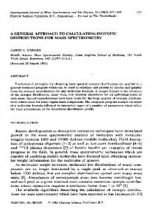
vector (centroid) as the pattern for the corresponding class. Many experiences have been carried out showing general good performance of the classifier. For illustration purposes we show now some significative results in the form of confusion matrices (see Fig. 5). Each element of the confusion matrix indicates the percent of the modulation type showed on the left side which is classified as the modulation type indicated in the upper side. A non-classification (NC) condition was allowed by means of imposing Signal Processing
a threshold to the nearest pattern distance. Distances above this threshold leads to nonclassificable features. The feature vectors were obtained by means o f a radiocommunication signal simulator that gives us a great flexibility for performance evaluation and design purposes. The classifier was always trained with signals generated by the simulator, in a range of 20 to 40 dB SNR. The modulation index in AM is generated in the range (0.5 ~ 0.8). The ratio fd/fmax, where fd is the frequency deviation and fma, is the m a x i m u m frequency in FM emissions is in the range (1.0~
L. Vergara Dominguez et al. / Automatic classification of radiocommunication signals
5.0) and the carrier reduction in SSB is in the range ( 1 0 d B ~ 3 0 d B ) . The carrier variation range is (0.1 ~ 0.4), in normalized frequency units. The distribution of values in all the above ranges is uniform. We have generated 100 simulated emission records for each modulation type, with different SNR conditions as we explain now. We show in the first confusion matrix (Fig. 5(a)) the general good performance when SNR is between 15 and 40 dB. The performance is also good (see Fig. 5(b)) when the SNR ratio is always high (40 dB). Nevertheless when we go under the minimum SNR value (20 dB) used for training, the performance clearly degrades, specially for the ASK2, FSK2 and FSK4 modulation types. This can be seen in the third confusion matrix in Fig. 5(c). When bias correction is applied to the patterns we can significatively improve the classification rates as is shown in Fig. 5(d). Finally, the fifth confusion matrix in Fig. 5(e)indicates that as we go deeper under the minimum SNR used for training, the performance degrades for almost all the modulation types. Nevertheless the degradation is in the sense of 'non-capability of the classifier to determine the type of modulation' (see the non-classification column) which is always better than producing erroneous classifications.
5. Conclusions
249
could be appreciated in the paper, an analytical development to exactly predict the influence of the many different system parameters on the overall performance would be very interesting. This is not in general an easy task. In some cases only experiments with exhaustive simulated or real data can give some idea of the mentioned influence. Nevertheless, the authors are now carrying out a study to analytically predict the behaviour of the confusion matrix under different signal-to-noise ratio and other perturbation effects coming from errors in the feature extraction subsystem. We hope to present the results in a future publication.
Appendix A Let {xi~}, i = 1 , . . . , k, I-- 1 , . . . , N,, be a feature vector set (k classes and Ni vectors in each class). We are searching for vectors aj (class j) such that 1, j=i, aTx"= O, j ¢ i ,
(A.1)
or, in matrix form
Axit =
(A.2)
li,
where A=
(A.3)
L. l We have presented in this paper a general scheme for radiocommunication signal classification, in particular modulation type detection. Although conceptually simple, some important practical problems make it necessary a careful design of the feature extractor and an adequate training of the classifier. We have successfully solved the problem for a 12 different modulation type environment, although the proposed scheme can be extended to include new modulation cases (probably with some small modifications of the feature extraction and the classification subsystems). As it was mentioned in the Introduction and it
and 1~ is a vector with a 1 in its ith position and zero the remainder. We can express (A.2) in another way
aV~X= z T= [ 0 0 0 . . . 1 1 1 . . . 000] T,
(A.4)
where X=[X11,X12,...,XkN,]. Z~ has Ni ones beginning in the position corresponding to the modulation type. Equation (A.4) shows an underdetermined system which has more equations than unknowns. So, it has no solution in general, but we can search for a vector ai which minimizes
Ilell ~ : II"TX- zTII=
(A.5) Vol. 22, No. 3, March 1991
L. Vergara Domfnguez et al. / Automatic classification of radiocommunication signals
250
f i n d i n g t h e s o l u t i o n [3]
a~ = z ~ x T ( x x ~ ) -1,
(A.6)
and, if we realize that N i
z ~ X v = • xS = Nim~,
(A.7a)
I--1
XX v= NR,
(A.7b)
w h e r e mi a n d R a r e t h e e s t i m a t e s o f t h e m e a n v e c t o r a n d a u t o c o r r e l a t i o n m a t r i x o f t h e xil v e c t o r s a n d N is t h e t o t a l n u m b e r o f signal v e c t o r s , w e a r r i v e to (4.2).
References [1] J. Aisbett, "Automatic modulation recognition using time domain parameters", Signal Processing, Vol. 13, No. 3, October 1987, pp. 323-328.
Signal Processing
[2] R.O. Duda and P.E. Hart, Pattern Recognition and Scene Analysis, Wiley, New York, 1973. [3] G.H. Golub and C.F. Van Loan, Matrix Computations, Johns Hopkins Univ. Press, Baltimore, 1983. [4] F. Jondral, "Automatic classification of high frequency signals", Signal Processing, Vol. 9, No. 3, October 1985, pp. 177-190. [5] F.F. Liedtke, "Computer simulation of an automatic classification procedure for digitally modulated communication signals with unknown parameters", Signal Processing, Vol. 6, No. 4, August, 1984, pp. 311-323. [6] J. Portillo-Garcfa, L. Vergara-Domfnguez, J.M. P~iezBorrallo and B. Ruiz-Mezcua, "Modulated signal classification: A general approach", Proc. lASTED Inter-
nat. Syrup. Applied Control, Filtering and Signal Processing, Geneva, Switzerland, 15-18 June 1987, pp. 127-129. [7] L. Vergara-Domfnguez, J.M. P~iez-Borrallo, J. PortilloGarcia and B. Ruiz-Mezcua, "A radiocommunication signal classifier", Proc. EUSIPCO-88, Grenoble, France, 5-8 September 1988, pp. 1361-1364.