less than the beam-front transit time across the gap. Using this relationship, tran- sient and time- ... given in Eq. (41, then. Eqs. (1) - (3) imply that the electric field.
© 1985 IEEE. Personal use of this material is permitted. However, permission to reprint/republish this material for advertising or promotional purposes or for creating new collective works for resale or redistribution to servers or lists, or to reuse any copyrighted component of this work in other works must be obtained from the IEEE.
2516
IEEE Transactions on Nuclear Science, Vol. NS-32, No. 5. Ocrober 1985 A GENERALIZATION OF THE CHILD-LANGMUIH RELATION FOR ONE-DIMENSIONAL TIME-DEPENDENT DIODES Abraham Kadish,
William
Peter,
and Michael
E. Jones
Applied Theoretical Division Los Alamos National Laboratory Los Alamos, New Mexico 87545 INTRODUCTION The steady-state Child-Langmuir relatior. between current and applied voltage has been a basic principle upon which all modern diode physics has been based. With advances in pulsed power technology and diode design, new devices which operate in vastly different parameter regimes have recently become of interest. Many of these devices cannot be said to satisfy the strict requirements necessary for Child-Langmuir flow. in a recent pulsed electron device for For instance, USI in high-current
the applied voltage 2 In another case, development is sinusoidal in time. of scurces for heavy ion fusion necessitates understanding of transient current oscillations when the voltage is applied abruptly. We derive the time-dependent relationship between the emitted current and time-depecdent applied \roltage The relationship in a “onrelativistic planar diode. is valid for arbitrary voltage shapes V(t) applied to the diode for times less than the beam-front transit Using this relationship, trantime across the gap. sient and time-dependent effects in the start-up phase of any ncnrelativistic diode can be analyzed.
We shall use Eqs. (1 ), (21, and (51 to obtain a generalization of the Child-Langmuir relation for time-dependent diode problems. In particular, a relation between the line-integrated current, K(t), and the applied potential will be obtained as well as a relation between the potential and the current emitted at the diode source. Equations (1) and :2) may be used to obtain an equation for j = nqv:
aj/at
+ a(jv)/ax
A RELATISN BETWEEN EMITTED CURRENT AND APPLIED VOLTAGE we derive a” equation which reIn this section, lates global properties of one-dimensional, nonrelativistic charged particle beam flow in a diode Our starting point is the set to the applied voltage. of cold plasma equations for the particle density, n, field, E. flow velocity, Y, and electric Zln/3t
+ a(flv)/3x
av/at
+ v^dv/ax
= qE/m
(2)
aE/ax
= “q/E,
.
(3)
have
particle
.
(6)
= 0
(1)
As is common in problems of tnis type, we will assune that particles are emitted with negligible velocity, so v(O,t) = 0. Thus, for nonvanishing current emission, an infinite number density is required at the source. We will also restrict ourselves here to the case of space-charge limited emission so E(O,t) = 0. Considering only times less than the beamfront transit time across the diode, niL,t) = 0, and we obtain from Eq. (3) and an integration of Eq. (6) dK/dt
= Nq2E(L,t)/2m
charge
3een employed
and m. MKS units -7 = c2 , where c DYE, x 10
and Tass are so that
q
the speed of light. The electric field 1s the gradlent of a potential Placing the current source at x = SO that E = -a$/ax. 0, and the collector plate cf the diode at x = L, the boundary -onditions for $(x,t) are taken to be
,
(71
uhere the total particle inventory of the density over the diode gap. L = q n(x,t)dx I 0
qN:t)
=
I 0
N is
t j(C,T)dT
the
\Ie not? vanishes, Employing
= -E,(dV/dt)
+ K(t)
integral
- c,E:L,t)
Equation (5) provides a relationship betdeen integrated current, the applied potential, emitted current density via the space-charge emission condition E(O,t) = 0, Lj(O,t)
The
= (nq’/c,m)E,E
accelerators,’
.
(8)
the lineand the limited
.
(9)
if
we require that the initial .current then dV/dt must also vanish initially. Eqs. (8) and (9) in Eq. (7) yields
is
$(o,t)
= 0
, $(L,+L)
= V(t)
(4)
,
where V(t) is the applied time-dependent voltage on the collector plate. If Poisson’s equation is solved for the potential wi:h tne boundary conditions given in Eq. (41, then Eqs. (1) - (3) imply that the electric field satisfies the
Amoere-type
+ Lnqv
= -E,(dV/dt)
+ K(t)
L K(t)
=
I0
nqvdx
.
(5)
(1C)
[i0 where
JI = (-c,/L!qV.
The
relationship
between
current density at the emitting surface plied voltage is obtained similarly:
and
t qj:O,r)dT
d[qj(O,t)l/dt-:/(2f,mL) [’ 0 = d2v/dt2
equation3
E,L(aE/“ot)
d[qK(t)/L]/dt=1/(2c,mL)
the
the ap-
2 I (11)
Equations (10) or (11) are generalizations of the Child-Langmuir relation for time-dependent diode problems. They describe the current pulse obtained from an applied voltage V(t), or conversely, define a voltage shape V(t) needed to extract a current density @oth relationships are only j(O,t) at the source.
aO18-9499:8511ooO-2576$01.000 1985 IEEE
2577 valid for the dicde
times less tnan the beam transit since they have been obtained
using
condition
tne
n!L,t)v’(L,t)
CYLINDRICALLY
time across from Eq. (7)
= 0.
AND SPHEHICALL~ SYMME'TH~C DIODES
The position r = r2 is held at zerc 1’ Solving Poissoo’s equation for the potenDotential. One tial determines the radial electric field, E geometry f lnds that in cylindrical >r
2
aruat
+ rj/Eo
= (In while
geometry
+ f- .J/E~
= (‘jr,-l/r*)-‘[dVidt In these
If
and
r2
=
!
(13)
J(t,r’)dr’
.
(14,
rl
we assume constant space-charge limited emisin the Lagrangian frame of the beam front, the fields are then given by rbE(t,rb) = r2jOt/c,
rb2E(t,rb)
d2rb/dt2
the
cylindrically
and
respectively. symmetric cases, satisfies tne differenthe beam front
(15)
= (qjO/E0m)(r2/rb)t
cylindrically
d2rb/dt2
for
= r22jOt/E,
spherically Consequently, t ial equations
in the
+ K(t)/Eo]
equations,
K(t)
s:on, electric
(12)
+ K(t)/E,,l
2
2
ar E/at
symmetric
diode
and (16)
= (qjo/cOm)(r2/rb)2t
We note that the :n the spherically symmetric diode. beam-front transit time is greatest in planar and least in spherically symmetric diodes. For steady flow behind the beam front, K(t) may be evaluated using the relationships rj(t,r) = r2j0 or 2. = r2jo.
r2j!t,r)
Substitut:ng
propriate differential
Ampere-type equations
cylincrical
symmetry,
dV/dt
symmetry
LIL;’ cbtain - 1 /rb)
= (r:jO/EO)(l/r,
(1%)
We note that the beam-front positions which appear :n Eqs. (17) and (ld) are determined by Eqs. (15: and The latter equations do not contain the poten(16). Consequently, Eqs. (15) and (16) may Se tial v(t). integrated directly to provide the source terms in the differential equattocs for Vit) to yield
t V!t)
= (r,jO/EO! i
In rb(T)
dr - (Inr,)t
(19)
b and -t V(t)
in the
= (r:jc/c
,!
t/r
1
-
I 0
r,‘(r)dr
(20)
two geometries. SU?PRESSION OF CURRENT TSANSIENTS
r2/r,)-‘[dV/dt
i? sphericaL
in spherical dV/dt
In this section, we generalize the treatment for planar d:odes to cylindrically and spherically symIn these geometries, the presence of metric diodes. of the continui:y equation raJ:al moments in integrals prohibits one from obtaining a simple relationship beHowever, tween emitted current and applied voltage. in the special limiting case of constant emitted curthe limiting voltage moy be obtained by rent, numerically integrating two ordinary differential equations. We assJrIe that a potential V(t) is applied at the jo( t) , is extracted A current, collector at r = r,. atr-r
while
= (r2jO/EO)
the
equations relating
result
for V(t)
in the ap-
E, we obtain and r,(t). In
we find In
(r3/r,
)
(17)
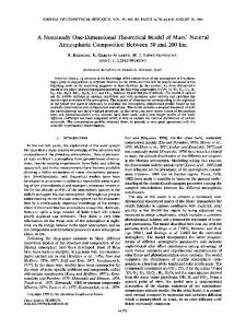
The analyses in the previous section provided an expression for the applied voltage iinich will produce a constant current in time. In real diodes, however, the appropriate initial condition is that the current vanish at t = 0 (V = 0) and therefore cannot be constant for all time. Therefore if the voltage predicted by Eqs. (19) or (20) or the equivalent voltage proflle for the planar diode 121, is applied to the diode, there will be an initIa1 start up period where the current rises from zero to the predicted constant valde. Furthermore, real diodes only approximate the special cases of planar, cylicdrical or spherical configurations. Therefore, in order to assess the usefulness of these solutions to real diodes, simulations of a diode design for heavy-ion fusion experiments were performed. Figure 1 shows the electrode configuration and a snapshot of the ion positions froni a simulation of a sodium ion diode designed for experiments at Los The calculations were performed with the Alamos [5]. 2-dimensior.al, particle-in-cell simulation model ISIS Figure 2b shows the current measured at the iI61. right-hand end of the simulation region shown in Fig. of time for the applied voltage shown 1, as a function in Fig. 2a. The voltage risetime is 10”s. The diagnotic measures zero current ur.til the particles reach the end of the simulation region, then rap:dly overshoots the steady-state space-charge limited current and then decays to the steady-state value. The voltage profile shown in Fig. 3a was obtained by approximating the diode shown in Fig. 1 by a spherical diode and using Eq. (20). The voltage risetime is clearly much slower than tie current risetime shown in Fig. 3b. Althcugh the current profile is not exactly a step-function predicted by the simplified models, it has much less overshoots than the calculation in Fig. 2, while maintaining a fast risetime.
1578 REFERENCES
7-o-
rb-$ 3*5y 2);;
1.
and Rickey J. Faehl, w. Peter Electron Source for Accelerator Proc. of the 1984 IEEE International on Plasma Science, St. Louis, 1984, p. 47.
2.
M. Lampel and 3, 57 (1933).
3.
“An Electrodynamic A. Kadish, Virtual-Cathode Oscillations,” National Laboratory report 1984).
4.
A. Kadish, W. Ceneralizaticn of One-Dimensional Alamos National (October 1984).
5.
H. L. Rutkowski, .A. W. Ehler, L. S. H. Humphries, and R. Shurter, Sot. 9, 1316 (1984).
6.
G. Gisler, ~nys. Sot.
h-4 F1g.
1
ISIS simulation snapshot showing figuration and particle positions.
dicde
con-
-2002 a0
16-4 4c“0
EQO
300 Nns)
Fig. 2
(a) Voltage profile simulation. (b) Resulting overshoot.
-2001 a0
I
for
10 ns risetime
current
profile
\
in ISIS showing
I
tb-4 E:g.
3
ISIS simulation showing (a) tailored voltage profile (b> nearly step-function resulting current profile.
“A New Pulsed Applications,” Conference MO, May 14-16,
M. Tiefenback,
Appl.
Phys.
Lett.
Interpretation of Los Alamos LA-9908 (January
Peter, and M. E. Jones, “A the Child-Langmuir Ralation for Time-Dependent Diodes,” Los Laboratory Report LA-10207 S. Engelhardt, Bull. Am. Phys.
M. E. Jones and C. M. Snell, 3, 1208 (1984).
Bull.
Am.