A Web-Based Mobile Robotic System for Control and Sensor Fusion Studies. Christopher ... arms, and other instruments can be integrated with little effort. Further, the iRobot .... board by Arduino is used for implementing the ANFIS controller in ...
A Web-Based Mobile Robotic System for Control and Sensor Fusion Studies Christopher Paolini1, Gerold Huber2, Quentin Collier3 and Gordon K. Lee1 1
Dept of Electrical &Com Engr. 5500 Campanile Drive San Diego State University San Diego, CA 92182
2
Abstract This paper presents a hardware system architecture for a mobile robotic system that employs multiple sensors (an ultrasonic array, a thermal sensor, and a video streaming system) to obtain information about the environment, a virtual field strategy for obstacle avoidance and path planning, and an ANFIS controller for path tracking. The particular focus is on the ANFIS controller and its hardware implementation, the graphicsuser interface and the overall system architecture. Experimental results and preliminary evaluation show that the proposed architecture is a feasible one for autonomous mobile robotic systems. Keywords: adaptive neural fuzzy inference control, multisensor integration I.
3
Management Center Innsbruck University of Applied Sciences Universitätsstraße 15 6020 Innsbruck, Austria
INTRODUCTION
The design of autonomous mobile robotic systems is a complex problem involving many tasks including (a) the development of a control strategy that can compensate for unknown system dynamics and which can change depending upon required tasks and environmental uncertainties; (b) the assembly of several sensors that can provide information to the controller about the robot’s current location and surrounding environment; (c) a path planning algorithm to avoid obstacles which achieving a goal and (d) the integration of the associated software and hardware support for a complete system platform. Several authors have addressed the issues associated with building and designing mobile robotic systems for a multitude of applications. For example, in [1], the authors provide a simple robotic design for educational purposes: a Lego Mindstorm© platform with a simple camera and sonar sensors is used to generate experiments to track objects. The platform includes a Handy Board microcontroller board, the CMU camera and a SRF04 sonar sensor. Further, many researchers have developed control techniques for mobile robotic systems. For example, in [2] the authors develop a fuzzy velocity controller for the Nomad 200 mobile robot. The controller uses a wallfollowing strategy with both angular and linear velocity.
IUT de Bethune Networks & Telecomm Dept. 62408 Bethune, France
Li [3] and others designed a real-time fuzzy target tracking control method for autonomous mobile robots by using infrared sensors to obtain target information and then a fuzzy controller for path tracking. In [4], Liu and others used genetic algorithms and fuzzy logic for path planning with obstacle avoidance. In this paper we employ an ultrasonic array and a thermal sensor to generate data about a mobile robot’s environment, including the potential for animate objects such as humans and animals, a virtual field theory to define objects based upon the sensor data and a path planning method using a grid structure, an initial measurement unit (IMU) and an adaptive fuzzy inference neural network controller for path tracking, and a novel video streaming technique to send images of the robot’s environment back to a user at a remote site. Further, we have developed the software and hardware to implement these tasks into overall robot architecture. In [5], we reported on some simulation results using the ANFIS controller. The main contributions of this paper include the development of a new internet driven user-interface, hardware implementation of the multi-input, multi-output (MIMO) ANFIS controller, the integration of this controller into the overall robot platform, and the evaluation of the architecture under several goal scenarios. This paper is organized as follows: for completeness, Section 2 presents the sensors that have been developed for this robot platform as well as the virtual field method and grid generation tasks for path planning. Section 3 presents the ANFIS controller, that is, the control strategy and hardware implementation. In Section 4 the system integration process is discussed while experimental results are provided in Section 5. Finally a summary of the activities to date and future plans are given in Section 6. II.
THE MOBILE ROBOT TESTBED AND SENSOR CONFIGURATION
In order to test the ANFIS controller as well as other learning systems, a mobile robot testbed has been constructed at San Diego State University. The platform for the robot is the iRobot Create® system, which is a version of the vacuum cleaning robot Roomba®. The platform is designed in such a way that sensors, robotic
arms, and other instruments can be integrated with little effort. Further, the iRobot Create® platform contains a variety of sensors that can be controlled with the iRobot Create’s® Open Interface® (OI). The mobile robot platform contains several sensors [6] as well as an adaptive AJAX-based streaming video system [7]. Video is captured from an onboard camera connected to an embedded single board computer (SBC) through an IEEE 1394 (Firewire) serial interface, all set within the robot’s payload bay. Unlike other video streaming techniques, through a novel software architecture, the data rate incurred by the video stream adapts according to the data rate available to a wireless Ethernet interface. The iRobot captures, encodes, and transmits the source stream to a gateway video server over a wireless network. The streaming video server then relays the stream to all Web browsers that are presently browsing the server. This architecture allows multiple people to remotely view the iRobot without increasing the data that is transmitted from the iRobot to the streaming video server.
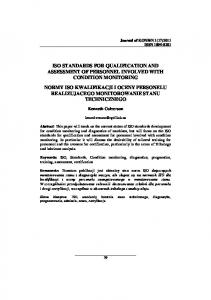
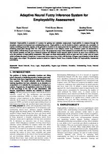
Figure 1: iRobot Create® with Ultrasonic Sensor Array Figure 1 shows the customized iRobot Create® mobile robot developed at San Diego State University. Mounted within the cargo bay is a Migrus C787 DCF-P single board computer (SBC) with a 1.2GHz Eden ULV Processor. This SBC is designed for digital media devices and home entertainment centers and has a Mini-ITX form factor of 17 cm-sq. The Migrus C7 has one 16-bit (PCMCIA2.1) card socket and one Compact Flash (CF) socket. A Debian derived distribution of the Linux operating system called Voyage Linux, designed to run on embedded x86 platforms, is used for the SBC’s operating system. The acrylic case also holds in place an external 12V 4200mAh Ni-MH rechargeable battery which supplies power to the Migrus C7, the FB-4652, a Unibrain Fire-i™ Digital Camera, and a custom circuit that allows the iRobot to dock and recharge the external 12V Ni-MH battery through the charging base. The Unibrain Fire-i™ is connected to the Migrus C7 through a 400Mbps IEEE1394 interface and supports a video resolution of
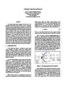
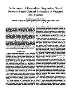
640x480 pixels with a maximum frame rate of 30 frames per second (fps). WLAN connectivity is provided through a Linksys Wireless-G notebook PC adapter card, model WPC54G v1.2, which is plugged into the PCMCIA port on the Migrus C7. The Linksys Wireless-G interface supports data rates of up to 54Mbps. Besides the video system, the robot platform has a thermal sensor and an ultrasonic array sensor system. The thermal sensor is used to detect animate objects which must be avoided as the robot traverses an area [9]. For thermal sensing, a TPA81 sensor is used which can detect infrared data in the 2m- range. The sensor has eight thermopiles arranged in a row and can measure the absolute temperature of 8 adjacent points simultaneously. The TPA81 module also has a servo that can be used to pan the thermal sensor and construct a thermal image. This sensor has an I2C interface. As a calibration check, both animate and inanimate objects were tested; the thermal sensor is able to detect a candle flame at a range of 6.5 feet and a human body at a range of 3 feet. For the mobile robot, the TPA81 sensor is used in conjunction with a servo to pan a space. A thermal image of heat can be built from 8 adjacent points simultaneously. The resulting image is a 32x8 pixel bitmap. Object detection is measured through an array of 10 MaxBotix LV-EZ1 ultrasonic range finder sensors (Figure 2). The LV-EZ1 is a 42 KHz transducer that provides three forms of communication: serial, analog, and Pulse Width Modulation (PWM). These sensors provide sonar range information from DMIN=6 inches to DMAX=254 inches with 1 inch resolution. Each sensor can be connected to either a 3.3 V or 5.0 V microcontroller supply and consumes less than 2 mA of current. Our system requires a total of 10 ultrasonic sensors to cover a 360 degree Field of View (FOV). When firing two or more sensors at the same time there can be crosstalk between sensors. Crosstalk causes unstable readings that can be interpreted as an obstacle that does not exist. To overcome crosstalk, the LV-EZ1 sensors provide a Daisy Chaining mode that allows multiple sensors to work together without interfering with each other. The total time for the chain to update 10 sensors is 2 Hz.
Figure 2: The Ultrasonic Sensor Array and ANFIS Microcontroller
The objective of the mobile robot presented here is to traverse an unknown area while moving towards a goal while avoiding obstacles. For this project, the Vector Field Histogram (VFH) and Virtual Force Field (VFF) methods were implemented to achieve real-time obstacle avoidance using ultrasonic sensor data. The VFH allows the detection of animate and inanimate objects in an unknown environment. The VFF method uses a Certainty Grid (CG) to store confidence values derived from ultrasonic sensor readings. The CG forms a localized map of a robot’s environment and is used to determine if an obstacle exists at a particular distance from the robot at a given time. The method focuses on an obstacle representation by using a two-dimensional Cartesian histogram grid. Each cell (i,j) in the grid holds a Certainty Value (CV) which represents the likelihood of an obstacle lying within cell (i,j). Similar to the Histogramic In Motion Mapping (HIMM) method [8], only the cell (i,j) that corresponds to the sonar distance is updated by a constant. The corresponding cell (i,j) is the one that lies at the acoustic axis of an ultrasonic sensor’s FOV. A different variable updates the remaining cells. The corresponding cells are the ones that lie on the acoustic axis. In this way, subsequent readings will clear high CVs if the obstacle has vanished from the FOV of an ultrasonic sensor [9]. The histogram grid is a virtual window that follows the iRobot Create® platform at all times. A 2D histogram grid is generated and mapped to a Cartesian coordinate plane, based upon sensor information. A nine degree-of-freedom IMU, developed by sparkfun [10] is used for heading information; the device contains a triple-axis accelerometer ADXL345, a singleaxis gyro LY530ALH (yaw), a dual-axis gyro LPR530ALH (pitch and roll) and a triple-axis digital magnetometer HMC5843. With the Atmega328 and a modified version of open source code [11], the sensor board becomes a Direction Cosine Matrix (DCM) based Attitude Heading Reference System (AHRS) with gyro drift correction using an accelerometer (gravity) vector and magnetometer (compass) vector.
gradient method. In this effort, we use the Kalman Filter formulation for the least-squares estimation:
T S a a i1Si Si1 Si i i1 , i 0, 1, ..., P 1 1 aT i 1Sia i 1 T X i1 Xi Si1 a i1 (b T i1 a i 1Xi )
(1) where ai and bi are values obtained from the datasets [13], Si is a covariance matrix, and Xi is the current least squares estimate of the consequent parameters. P is the number of datasets. In the backwards pass, the gradient method minimizes the error measure defined by: P
E
i 1
P
Ei
(y i y di ) 2
i 1
P
ei2
(2)
i 1
where yd is some desired or target output, y is the actual output, and ei = yi - ydi is the error of the network. This gives the premise parameters. To revise the filter equations for on-line (unsupervised) learning and to reduce the effects of old measurements, an appropriate approach is to discount the measurement exponentially. Thus, an observation that is samples old carries a weight that is of the weight of the most recent observations, where 0<