panel type shows a list of videos and plays the selected video. The command panel allows ..... Aided Design of User Interfaces. Valenciennes, France May. 2002.
A Generic Description Language for the Automatic Generation of Pervasive Medical User Interfaces: The SEFAGI project Tarak Chaari, Brahim Elloumi, Frédérique Laforest LIRIS-CNRS, INSA de Lyon, France {tarak.chaari, frederique.laforest}@liris.cnrs.fr Abstract The SEFAGI project (Simple Environment For Adaptable Graphical Interfaces) aims at designing an architecture to adapt applications to multi-terminal environments. Our main objectives are: (i) allow the end-users to describe their user interfaces and automatically generate the entire corresponding code and (ii) make the code generation adaptable to any kind of Java-enabled terminal. Our generator currently allows the generation of user interfaces for three types of target platforms: standard terminals, limited mobile terminals and high capacity mobile terminals. This led us to define a language for describing the target platforms, independently from windows descriptions. New platforms are thus easier included. Key words Adaptation, user interfaces, code generation, abstract window description, platform description
1
Introduction
Nowadays users want information to be available everywhere, at any time and on any terminal. Pervasive information systems aim at answering these requirements (Birnbaum, 1997). This implies the introduction of mobile terminals with heterogeneous hardware and software capabilities. Moreover, each user would like to have a customized application. In particular, the medical domain presents many situations where mobility is a key factor, or the professional, and thus also for the data and services required. Getting a medical record, accessing a drugs database or any other kind of information is of great interest for all care practitioners, when he/she is out of office (for example when visiting a patient at home). The provided user interface should not be the same at all places and for all terminals. User interfaces development requires a high percentage of the entire application development time (Myers et al, 1992). In the new pervasive information systems, this constitutes an important bottleneck: the problem grows as the number of terminal types increases. The number of required user interfaces grows with the number of end-users too. That is why works on automatic generation of user interfaces code (or part of it) are numerous today. They are of great interest in pervasive systems. In this paper, we present our work on the adaptation of user interfaces to different types of terminals. We also show how we simplify the creation of many user interfaces. To reduce the necessary effort for the construction of user inter-
faces, we have decided to involve end-users very early in the process: end-users describe themselves the windows they require. The SEFAGI environment permits: • the description of expected user interfaces based on an abstract window description language, • the description of target platforms based on a platform description language, • the automatic generation of windows code using the previous descriptions. Platforms descriptions provide technical information that requires the knowledge of a computer scientist. Once a platform has been described, it can be used for the generation of any window for this platform. Abstract windows descriptions can be made by end-users themselves: it is a rapid and simple description. Any end-user can then run the generator that builds autonomously the entire window code for selected platforms. Our work has concerned the definition of the two description languages and the design of the generator. After presenting a rapid overview of the SEFAGI project, we introduce related works in user interfaces generation. We then present in details the SEFAGI architecture, our abstract windows description language and our platform description language.
2
Quick overview of the SEFAGI project
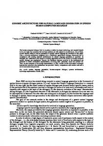
The SEFAGI project (fig 1) aims to design and build a platform that allows users with different terminal types to access the same application services. In SEFAGI end users describe application windows using our abstract XML description language. This language (described later) is not much detailed so that descriptions are easy and rapid to write. Moreover, users don’t really write abstract descriptions: a graphical assistant offers an interactive design process and hides the language syntax. To design a window, the end user chooses in one click a group of graphical components (a standardized SEFAGI panel) in a library. He then links it to a service by navigating in the services repository. On the other side, platforms descriptions are provided by computer scientists. Such descriptions are made using our XML grammar. An implementation of abstract basic graphical components also has to be provided for each platform. SEFAGI automatically generates the code of each interface, including its presentation and its behavior. Code is entirely written for each window and for each platform. In this kind of projects, the underlying technologies have an impact on technical solutions and proposed architectures. We have chosen applications made of distant web services
and Java user interfaces. The interests of web services are now well known: they allow the use of decoupled components, interacting in an easy way with a standard protocol. Using Java-based user interfaces allows building highly interactive interfaces, unlike web interfaces. Generated interfaces are executed on terminals in a dedicated runtime environment. Each type of platform requires a different runtime environment code, as it depends on the available platform API. Platforms descriptions are used to build automatically the code of the runtime environments. Platforms descriptions Administrator describing new platforms
Graphical Assistant
SEFAGI generator
Windows descriptions End-user
Describing new windows
execution environments windows
Using the adapted application
Figure 1 General presentation of the SEFAGI project
3
Related works
We can find several user interfaces description languages in the literature. UIML (Abrams et al, 2002) which is based on presentation domain and dialog models to describe the graphical components of the user interface, the data displayed to the user and the human computer interaction between the interface and the user. TIDE is the design tool used to describe UIML user interfaces. Then LiquidUI generates the source code of these interfaces. AUIML (Calvary et al., 2003) which is a derived language from UIML that separates data from display components. AUIML Visual Builder generates user interfaces based on the AUIML language. The target terminals of these builders are Standard PCs. SunML (Pinna-Dery et al, 2002) is another language based on UIML that focuses on the business objects that the interfaces interacts with. It offers advanced operators to compose and project SunML user interfaces to many target concrete languages (HTML, C++, VoiceXML…). XIML (Puerta, 2002) and USIXML (Coyette et al., 2005) focused on modelling all the aspects of a user interface: its interaction with the user, its presentation, the tasks that it accomplishes, the data that it siplays and the target platform where it will be diplayed. These languages offer rich and thorough descriptions of Multi-Platform user interfaces but the big amount of the required details and the complexity of their modes considerably reduce their utility. PlasticML (Rouillard, 2003) tries to reduce the complexity of the existing languages by separating interface and non-interface code. The designers of PlasticML provided a tool (plastic ML toolkit) to facilitate user interface rapid prototyping. This tool can provide only webbased user interfaces. As a conclusion, we can say that there are many sound contributions to multi-platform web based user interface gen-
eration domain like PlasticML and the W3C recommendation XForms (Raman, 2004). They provide a very degree of platform independence. The Teresa (Mori, 2004) project goes beyond logical user interface description and adds task models to describe the activities that the interface will support before building its code. Despite such rich and solid contributions, there are few solutions for the automatic generation of object-oriented user interfaces. In fact, object oriented interaction programming is very different from web based scripting. The design of the user interface, their interaction with the user and with application’s services is based on more complex objectoriented formalisms (aggregation, inheritance…). These user interfaces provide more sophisticated interactions and more comfortable data exploration. Moreover, few projects externalize platforms descriptions from windows description. Consequently window descriptions become long and fastidious, and cannot be made by end-users. Secondly, the defined languages to model user interface components present a very fine granularity. The user has to describe all the properties of each component in the user interface and their entire hierarchical organization. This constitutes a problem when we want to help noncomputer experts to describe and generate user interfaces. In this paper, we present a simple and comprehensive user interface language and a platform description language to automatically generate user interface for multiple platforms.
4 4.1
The SEFAGI generator Architecture of the generator
The generator architecture can be decomposed into two layers: a generic layer that contains platform-independent components and a specific layer that depends on the target platforms, as presented on fig. 2. The generic layer is mainly composed of the generator and languages to describe platforms and windows. These languages are XML DTDs. They are described later in this paper. Abstract windows descriptions are also totally independent from target platforms. They are in the generic layer. Our generator includes two modules: the generator of runtime environments and the windows generator. The runtime environments generator takes as input the specific vocabulary of a platform and builds automatically and entirely the code of the corresponding necessary classes to run the generated windows. This is done once for each new platform description. The windows generator takes as input the description of a window and the description of each platform to build automatically and entirely the window codes adapted to the target platforms. The specific layer contains XML descriptions of platforms. They are used as input for the generic generator. The generated codes for windows and runtime environments are also at this specific layer: they constitute the generator output.
Conforms to
Window description DTD
Platform description DTD
Abstract Abstract Window Abstract Window Description Window Description Description
Generic Layer
SEFAGI generator Execution environments generator
three classes. The Model class manages user identification and the dialogue with Web services. The View class includes the definition of the graphical components of the user interface, their initializations, setters and getters. The Controller class includes events management and transmission of services calls.
5
Windows generator
Languages for windows and platforms descriptions
Conforms to
Platform i Platform i Description Platform i Description Description
Execution Execution Environment Execution Environment Codes Environment Codes Codes
Windows Windows Codes Windows Codes Codes
Specific Layer Figure 2 Architecture of the SEFAGI generator
4.2
Structure of the generated codes
The SEFAGI generator has first been developed separately for three categories of terminal: standard terminals, limited mobile terminals (CLDC profile, like smart phones) and mobile terminals with higher capacity (CDC profile, like PDAs). This has allowed us validating the generated codes. It also helped us designing the final generator and the platform description content. To design our final generator, the main work was to study and refactor our existing generators. This study allowed us to define a common architecture based on the platform-dedicated runtime environments and the generated user interfaces codes. The following sections introduce the results of this work by presenting the organization of these generated codes. We have defined a generic abstract structure for the runtime environment codes. This common structure is based on five layers. SEFAGIComponent corresponds to elementary graphical components like checkBox, MultilineText, and so on. Each graphical component in this generic library has an implementation in each platform API (eg a command SEFAGI component corresponds to a button on a standard PC and to an item in the right menu on a smart phone). SEFAGIPanel defines panels as groups of components that allow the manipulation of coherently grouped data (we have defined six panel types, like a table panel that allows for the manipulation of matrices, an image panel that permits to browse images, a command panel that asks for some services executions...). SEFAGIWindow is an abstraction of a generated window. SEFAGIMainContainer provides the facilities to display and navigate between the graphical entities of a window. SEFAGIMainWindow is the main program providing facilities to navigate between the different available windows. This generic structure has been applied to all platforms. It has been used as a basis for the design of the platforms description language. Windows code is generated from abstract windows descriptions. We have chosen to write the code according to the MVC standard structure. Each window code is divided into
5.1
Abstract windows description
User interface descriptions are often very heavy because of the huge quantity of details required to specify all parameters of each widget (size, position, color, events…). This is due to the low level description of reusable components. In this work, we have defined a higher level of reusable components called panels. A panel contains a set of grouped widgets that assures a typical functionality. Panels have been defined after practical user interfaces studies on the medical domain and we think they can answer many domain needs. Nevertheless, new panel descriptions can be added for specific needs. We have defined and implemented six panel types. The table panel type ensures capturing and presenting data in a grid. The text panel type ensures capturing and presenting a multi-line text. The graphic panel type presents graphs or histograms for 2D values. The image panel type shows a list of images and the selected image. The video panel type shows a list of videos and plays the selected video. The command panel allows executing actions on panels. Each panel is associated to Web services that allow to fill in the panel widgets or to update data from end-user captures. A window is thus defined as a list of panels. A panel is composed of a list of widgets which are associated to Web services input/output data. When a Web service is associated to a panel type, each input/output data is automatically associated to a panel widget. We have chosen to use an intermediate internal format to store windows descriptions. This Abstract Window Description is platform-independent: different codes for the different types of terminals will be written for an AWD. This intermediate format is based on XML. The XML file describing a window can be reused to create new windows or to update a window that requires modifications. The AWD generates documents that are smaller than other description languages that one can find in the literature. Many implementation details are not provided in AWDs as it remains at an abstract level. The interface rendering on the screen is not specified. This is an advantage for new windows construction as it guarantees efficiency (descriptions are rapid and the designer does not get lost in details) and consistency (no risk for widgets to overlap for example). But it can also be seen as a drawback: generated panels are “preformatted” and cannot be highly personalized. But the advantages it provides have largely covered this restriction in the case studies that we have done. The structure of windows
descriptions corresponds to the UML class diagram provided on figure 3. Window
Panel id type title
1..* initService 1 1
Service id accesspoint
1..* Component id type editable visible
Target Service
* Parameter name type
1 location
* Action Constraints
1
5.2.1
Logical Structure
The logical structure represents the hierarchy of the different graphical entities and their properties which will be used in each platform. The logical structure is composed of one or more "SEFAGIEntity" entities and each entity can be composed of several entities. Each entity is characterized by 3 attributes: its name, its superclass in the SEFAGI libraries and its properties. Figure 4 provides the corresponding UML class diagram and an example.
* Value firstValue type
SEFAGIEntity name superClass
*
Property name type
*
2..*
Figure 4 Logical structure of a platform description
Constraint
Figure 3 UML class diagram for AWD
A window has a name, a title, and is composed of a set of panels. A panel has a unique id in the window, a title, a graphical components set, and a set of services used to feed its graphical components. A default service is used to fill the panel when shown. A service has a set of parameters (input and output description), an id, an access point (name, server and port). Each parameter may have a default value, constraints (e.g. min and max), and a location. The location indicates in which other component its value should be read (group and specific references). A component has a unique id, a name, a type (among all available widgets; these widgets may have values restrictions, e.g. date, number).A component may also be editable and visible. The action element allows defining which service should be called when the element is validated (e.g. button click).
5.2
Platforms description
Describing target platforms in a dedicated document has two advantages. The platform description is not included in windows descriptions, so that these windows descriptions are simpler. The platform description is not embedded in the window code generator, so that adding new platforms is easier, and maintaining the generator or making it evolve is also more convenient. A platform description is written according to three facets: the logical facet, the behavioral facet and the physical facet. This directly comes from the windows components usual decomposition that defines these three structures: a logical structure describing the composition of elementary entities, a behavioral structure defining the interaction between these different entities, a physical structure defining their layouts on the physical screen. This separation simplifies the description of a platform. The following subsections explain the three structures.
5.2.2
Behavioral structure
We describe in the behavioral structure the behavior implementation of the different entities defined in the logical structure: instantiation, initialization and methods of the SEFAGIEntities. The behavioral structure defines for each entity its constructors and methods. An entity has a name and an implementation class. A method is described by its inputs and outputs, and also by a few code lines if necessary. This is shown on figure 5. < BehavioralStructure> … …
SEFAGIEntity
Constructor name {type=null} {output=null}
Instanciation object className returnInstruction
*
Method name type
output 0..1
Variable name type
input *
Instruction
Loop type expression
MethodCall object methodName Conditional type expression
Figure 5 Behavioral structure of a platform description
5.2.3
Physical structure
5.3
The physical structure defines the layout of the different graphical components. This layout follows some adaptation rules according to the target platform. This physical structure should depend on the output of the service that is in interaction with the window. Moreover, in small devices, multi-line results are decomposed in different screens, and the set of necessary screens constitute the window. The physical structure provides the layout of entities. It defines the number of necessary screens to show an entire complex component (i.e. SEFAGIPanel). Depending on the number of lines answered by the invoked service, the panel may be presented in a different manner. When necessary, navigation betweens screens of a window are defined. Each component also has an action to do when activated by the end-user. See figure 6 for an example and the UML class diagram of a physical structure. … …
1
*
Multiline ResultScreen
Monoline ResultScreen
SEFAGIEntity name superClass
1
1
Screen id
Layout type
ScreenComponent name occurs position 1
NavigationBetweenWindows NavigationBetweenPanels
Conclusion on description languages
The window description language that we have defined is very different from languages that we can find in the literature. It is much less verbose, and so creating a new window is much more rapid. On the other hand, it has many limitations on personalization. For example, it does not allow making much modification on the lookout of generated interfaces (widgets layout, coloring and so are predefined). The platform description language defined here has been validated on three different java based platforms: J2SE, J2ME and SuperWaba. Our language is generic enough to manage any java platform.
6
Case study
In this case study, we present a window that contains three panels : the first is a table panel showing patient file id, dialysis type and mode, date of the patient’s record creation and of its last modification, name and first name of patient. The second is another table panel which presents a temperature data list of the concerned patient. The third is an image panel. Figure 6 shows a SEFAGI generated window for a peritoneal dialyse medical application on standard PC. Figure 7 presents the same window for mobile terminals. On the standard screen, we can see the execution environment that manages the generated windows. A menu bar in the upper part of this window provides the list of the available windows in this medical application for the current user. This menu bar is translated as a root window on the mobile terminal. The first table panel, which presents general information on the treatment of a dialyzed patient, is shown as a matrix on the standard screen containing only one line. As it contains only one line, it is shown as a vertical list of items on the small screen. The second panel is shown as a matrix on the large screen. It is decomposed into two windows on the small screens: the first provides the first the dates when temperature has been measured; the second provides the line corresponding to the temperature value according the selected date, with a vertical disposition of items. The third panel is an image panel presenting medical images concerning the same patient. It is decomposed into three windows, one for each component. The small screen interface generates many windows and thus many navigation means. All navigation facilities are automatically computed at code generation.
Interaction
7
Conclusion and perspectives
1..* Command name className
NavigationBetweenScreens
Figure 6 Physical structure of a platform description
In this paper, we have presented the SEFAGI architecture which aims to provide a simple and convivial solution for the generation of Java multi-terminal user interfaces. This study led us to define a language for the abstract description of windows, and a language for the specification of platforms. We also have designed the prototype of a generator that allows for the complete generation of user interfaces and runtime environments based on windows description and platforms descriptions. The structure for the platforms description is generic (not dedicated to a specific plat-
form, as one can see in the literature) and is organized in three axes. The logical structure defines the hierarchy of the various graphical entities used. The behavioral structure describes the actions on and behavior of the various graphical entities defined in the logical structure. The physical structure provides the layout of the graphical entities on the terminal screen. The generic DTD that has been designed for the description of any platform helps to add new types of terminals and virtual machines to the SEFAGI generator easily. Among the perspectives of our work, we intend to develop the generator. Today we have only developed and validated three distinct generators for the three target platforms we have selected. We also intend to define a graphical assistant for the creation of platforms descriptions. Moreover, techniques of reverse engineering could be used to extract the description of the available graphical entities in each API. The use of ontology for the description of platforms should provide more expressiveness than the use of a simple XML grammar. We intend to study the advantages and the overhead induced by such ontology. Figure 8 A SEFAGI generated window for PDA screens [5] Coyette, A., Vanderdonckt, J. A Sketching Tool for Designing Any user, Any platform, Anywhere User Interfaces, Proc. of 10th IFIP TC13 Int. Conf. on Human-Computer Interaction Interact’2005, Rome, Sept. 2005. [6] Deakin N., XUL tutorial. Available at http://xulplanet.com/tutorials/xultu/. Last visited Feb. 11 2006 [7] Mori G., Paterno F., and Santoro C. Design and development of multideviceuser interfaces through multiple logical descriptions. IEEE Transactions on Software Engineering, 30(8):507– 520, 8 2004 [8] Myers B. A., Rosson M. B., 1992. Survey on User Interface Programming. Human Factors in Computing Systems, Proceedings SIGCHI'92. Monterey, CA, May, 1992c. pp. 195202. Figure 7 A SEFAGI generated window for standard PC screens
8
References
[1] Abrams M., Helms J. User Interface Markup Language (UIML) 3.0 Specification DRAFT, Document version 08 February 2002. http://www.uiml.org/specs/docs/uiml30-revised02-12-02.pdf [2] Ali M.F., A.Pérez-Quiñones M., Abrams M., Shell E., 2002 Building Multi-Platform User Interfaces With UIML. In CADUI'2002, 4th International Conference on ComputerAided Design of User Interfaces. Valenciennes, France May 2002 [3] Birnbaum. J., 1997. Pervasive Information Systems. Communications of the ACM 40 no 2, February 1997. [4] Calvary G., Coutaz J., Thevenin D., Limbourg Q., Bouillon L., Vanderdonckt J.: A Unifying Reference Framework for multitarget user interfaces. Interacting with Computers 15(3): 289308. 2003
[9] Pinna-Dery A.M., Fierstone J., Picard E.. “Component model and programming: a first step to manage human computer interaction adaptation”. In Springer Verlag, editor, “The 5th International Symposium on Human-Computer Interaction with Mobile Devices and Services”, LNCS 2795, pages 456-460, L. Chittaro (Ed.), Udine, Italy, Sept.2003. [10] Puerta P., Jacob E. XIML: A Common Representation for Interaction Data. IUI2002: Sixth International Conference on Intelligent User Interfaces. San Francisco, California, USA, Jan. 2002. [11] Raman T. V. XForms, XML Powered Web Forms. AddisonWesley, 2004. [12] Rouillard, J, Plastic ML and its toolkit, HCI 2003, Heraklion, Crete, Greece, 2003. [13] Vanderdonckt, J., Limbourg, Q., Michotte, B., Bouillon, L., Trevisan, D., Florins, M., UsiXML, A User Interface Description Language for Specifying Multimodal User Interfaces. In WMI'2004 W3C Workshop on Multimodal Interaction. Sophia Antipolis, France, July 2004.